
Subscribe to Our Youtube Channel
Summary of Contents for Rato RT150ST-A
- Page 1 RT150ST-A 维修手册 RT150ST-A SERVICE MANUAL 重 庆 润 通 动 力 有 限 公 司 Chongqing Rato Power Co., Ltd.
- Page 2 , This maintenance manual of four-wheeled vehicle model RT150ST-A (Hereafter called all terrain vehicle-ATV for short) compiled by Chongqing Rato power Co., Ltd is specially provided for saler and technical staff of our Group. This manual mainly introduce the maintenance, removing and repairing method of cross-country vehicle and provide some relative technology and performance data.
-
Page 3: Table Of Contents
Content Chapter I General description ........................... Section 1 Description ............................1 Section 2 Special tools, instruments and meters .....................2 (I) Special tools ............................2 (II) Instruments and meters..........................3 Section 3 Identification code, label of model and engine No ...................4 Section 4 Points for attention in maintenance ......................4 Section 5 Specification ............................8 (I) How to use conversion table of unit ......................8 (II)Basic specification ..........................9... - Page 4 Section 3 Maintenance and Adjustment of Vechicle Body ..................21 (I)Wear inspection of front&rear brake ......................21 (II)Adjustment of front brake ........................21 (III)Inspection of steering system ........................ 23 (IV)Adjustment of toe-in of front wheel ....................... 24 (V)Adjustment of rear shock absorber ......................25 (VI) Inspection of tire ..........................
- Page 5 (I) Removal steps............................50 (II) Inspection steps ............................ 51 Section 3 Steering Operation System ........................53 (I)Removal steps of steering bar ........................53 (II)Removal steps of steering vertical column welding ..................54 (III)Inspection content ..........................55 (IV)Installment steps ..........................56 (V)Installation steps of steering bar ......................
-
Page 6: Chapter I General Description
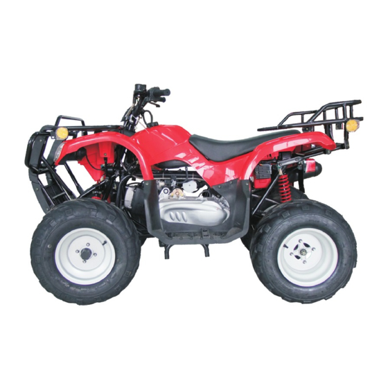
Chapter I General description Section 1 Description 1. Front wheel 2. Fuel cock 3. Cushion 4. Rear wheel 5. Exhaust silencer 6. Rear fender 7. Front fender 8. Bumper 9. Left lever of rear brake 10. Left switch unit 11. Fuel tank cover 12. -
Page 7: Section 2 Special Tools, Instruments And Meters
Section 2 Special tools, instruments and meters (I) Special tools Special tools is the necessary tools used for accurately adjustment and assembly, it is helpful to prevent the maintenance defects and components damage caused by using improper tools. 1.Wrench for valve adjustment mainly used for adjusting valve clearance. Specification:3mm 2.Puller for piston pin, mainly used of removing pistion pin. -
Page 8: (Ii) Instruments And Meters
(II) Instruments and meters The following instruments and meters can be selected with reference to the same type of vehicle. speedometer of engine multimeter Ignition timing meter spark tester of spark plug barometer ignition checker dial indicator measuring tool of gasoling... -
Page 9: Section 3 Identification Code, Label Of Model And Engine No
Section 3 Identification code, label of model and engine N0. Identification code Identification code It is engraved in the left or right side of front supporting main take of engine of frame. Engine N0. Engine N0. The engine No. engrave on the Narrow Point Position Section 4 Points for attention in maintenance embly, this in assembling, can not only increase the... - Page 10 4. Clip 4.1Before assembling, be sure to check all the clips carefully.Use a new one after remov- ing the clip of piston pin. When mounting clip ring ① make the sharp face ② on the opposite position of impacted face ③ of clip.(see left fig) 5.Locking washer /shim and location pin 5.1When reassembling after disassembling.
- Page 11 7.Check of electirc parts 7.1 Check the rust, dirt and moisture etc. of connector, if there is moisture, please blow it dry and clear the rust and dirt. 7.2 The eclectolyte inside the battery is a kind of corrosive, when operation exercise shall be taken not to let the electrolyte splash on the body.
- Page 12 b. If joint is slack, bend the plug pin upward, then connect with connector plug(see fig7.5) 7.6 Before mounting new fuse, check if the load of fuse of components is right, especially for the portion being burned broken regularly, Plug pin then mount the fuse having proper current value.
-
Page 13: Section 5 Specification
Section 5 Specification (I) How to use conversion table of unit (1)How to use conversion table All the specified documents in this manual are taken SI and Metric as unit. With the follow- ing conversion table, metric unit could be conversed into imperial unit. METRIC MULTIPLY IMPERIAL... -
Page 14: Ii.basic Specification
II.Basic specification Specification Specification Item Item Dimension: Frame: Bracket steel tube Overall length 1730 mm Caster angle 25° Overall width 1060 mm Tire: Overall height 1160 mm Type Tubeless Height of cushion 830mm AT21 ×7 -10 Specification of front wheel Axle base 1100 mm AT20 ×10 -10... -
Page 15: Iii.atv Body
III.ATV body Item Standard Limit Spock rim, tubeless tire Type Steel plate Material of rim Front AT 21× 7-10 Size of tire wheel 2.0mm Radial runout of rim 2.0mm Lateral swing of rim Drum type Type Front brake Spoke rim, tubeless tire Type Steel plate Material of rim... -
Page 16: Section 6 Wiring Diagram Of Atv
Section 6 Electrical diagram of ATV -11-... -
Page 17: Section 7 Requirements For Torque Of Fastener
Section 7 Requirements for torque of fastener (I) General torque specification General torque specification (standard screw) This table is screw locking specification drawn up by International Standard Association. In order to avoid the twist or unbalancing phe- nomenon when locking screw. please cross lock or londuit as per appointed orders. -
Page 18: Section 8 Lubrication
Section 8 Lubrication Standard Item (I) General torque specification :Pressure :Splashing oil Piston/cylinder Piston pin Connecting rod Valve Camshaft Automatic centrifugal clutch Crank Rocker Bearing Spindle Fine filter Branch valve Sprocket chamber Driving shaft Oil pump Middle gearbox Rough filter -13-... -
Page 19: Section 9 Lubrication Point And Type Of Lubricants
Section 9 Lubrication point and type of lubricants (I)Lubrication point and type of lubricants(ATV body) Lubrication point Type of lubricants Lip of oil seal (full) Light lithium-base grease O-ring (full) Light lithium-base grease Steering shaft(upper end,lower end) Light lithium-base grease Ball connection of steering pushing rod Light lithium-base grease Front wheel fork (ball-shaped joint) -
Page 20: (Ii)Lubrication Point And Type Of Lubricants(Engine)
(II)Lubrication point and type of lubricants(Engine) Lubrication point(name of component) Type of lubricant Lip of oil seal (Crank,shift gear shaft,spindle,shift gear operation shaft) Light lithium-base grease All bearing (Crank spindle, driving shaft, shift gear camshaft, Lubricating-oil pneumatic canshaft) O-ring (Contact position of o-ring) Light lithium-base grease Stem end of intake and exhaust valve (Intake and exhaust valve, vale adjsuting screw ) -
Page 21: Chapter Ii Maintenance And Adjustment Of Vehicle
Chapter II MAINTENANCE AND ADJUSTMENT OF VEHICLE Note: The correct maintenance and adjustment are necessary to ensure vehicles, normal driving.The repair personnel should be familiar with the contents of this article. Section 1 Periodic Maintenance/Lubrication Every Every time Item Requirement month month month... -
Page 22: Section 2 Disassembly And Assembly Of Cushion, Fender And Fuel Tank
Section 2 Diassembly and assembly of Cushion, Fender and Fuel tank Lock lever ( ) Cushion 1.Disassembly (1) Place the vehicle on the horizontal ground. (2) Disassemble the cushion Pull the cushion lock lever upward, then raise the tail part of cushion. By that, you can disassemble the cushion. - Page 23 Caution Battery Negative wire Positive wire Should disconnect the negative wire fistly. (4)Take out the battery. (5)Disassemble the rear fender. Rear fender 2.Installation Operate according to reverse procedure of “Disassembly”.Pay attention to following points: (1)Install: Rear fender (2)Install: Battery -18-...
- Page 24 (3)Install the cushion Caution Insert the support plug of cushion into the plug seat on the frame, then press down the cushion. ④ ② ① ⑤ ③ (III)Front fender 1. Disassembly: (1) Place the vehicle on the horizontal ground. ( 2)Disassembly the front carrier ① ( 3 ) D i s a s s e m b l y t h e b u m p e r p r o t e c t i v e plate②、...
-
Page 25: (Iv)Fuel Tank
(IV)Fuel tank 1.Disassembly (1)Place the vehicle on the horizontal ground (2)Disassemble the cushion (3)Remove the front fender and rear fender (4)Remove the fuel tank bolt (5)Pull the fuel cock lever to “OFF”position (6)Remove the fuel inlet pipe Caution Place a cloth on the engine to absorb the splashed gasoline. -
Page 26: Section 3 Maintenance And Adjustment Of Vechicle Body
Section 3 Maintenance and Adjustment of Vechicle Body (I)Wear inspection of front&rear brake 1.Check the front brake (1)Brake the vehicle with front brake (2)Check: .Wear indication .If the wear indication reach the wear limit mark,replace the brake shoe assy. Refer to section“Front wheel and front brake” 2.Check the rear brake (1)Thread down the rear brake pedal to brake the vehicle. - Page 27 2.Adjustment Lock nut Adjusting screw Adjusting procedure of free clearance of right lever: .Loosen the locking nut,and rotate the cable adjsuting screw clockwise to reduce the tension of front brake cable. .Pick up the front wheel from ground, and rotate the two front wheels, and ensure the two front brake’s brake force.
-
Page 28: (Iii)Inspection Of Steering System
(III)Inspection of steering system 1.Place the vehicle on the flat ground 2.Check: .Clamp seat of steering vertical column and sliding bearing on the lower end of steering vertical column, upper &lower and front &rear moving steering bar If the clearance is too large, replace the sliding bearing 3.Check: .Ball pin unit of steering tension rod. -
Page 29: (Iv)Adjustment Of Toe-In Of Front Wheel
(IV)Adjustment of toe-in of front wheel 1.Rest the motorcycle on the flat ground 2.Measurement: .Toe-in .Adjust if out of specification .Adjustment steps of toe-in. .Mark the centers of tire thread of two front wheel. .Lift the front end of motorcycle to keep the front wheel from force. -
Page 30: (V)Adjustment Of Rear Shock Absorber
Inspecion of front/rear shock absorber 1. Rest the motorcycle on the flat ground 2. Inspection (1) Front/rear shock absorber If scraped/damaged replace the front/rear shock absorbe (2) Oil leakage If the heary oil leakage of front/rear shock absorbers is found, replace it. 3.Inspection .Operation: .Shock the fornt /rear shock absorbers up and... -
Page 31: (Vi) Inspection Of Tire
(VI) Inspection of tire Warning This motorcycle adopted the low pressure tire,So correct filling pressure and keeping the proper pressure is very important. .Tire characterics 1)Quality characterics of tire will affect the driving reliability of ATV. The following types of tires reliability by our company be used safely by this motorcycle. -
Page 32: (Vii)Inspection Of Rim
1.Measurement .Tire pressure(nomal atmospheric temperature): If out of specification, adjust. Caution .The manometer of tire belongs to spare parts of the motorcycle(Never use the high pressure). .If the foreign matters such as dust, etc are absorbed in the tire pressure manoeter, the readig of the meter will be not correct, at the moment,the second measurement should be conducted and the second measurment reading should be adpoted. -
Page 33: Section 4 Maintenance And Adjustment Of Electrical Appliance
Section 4 Maintenance and Adjustment of Electrical Appliance (I)Inspection of battery Warning: The electrolyte is dangerous article, whitch includes sulphuric acid, so it is poisonous and corrosive. .Please operate by the following steps: a.Avoid the body touching the electrolyte so as to protect the eye from burn or damage. -
Page 34: (Ii)Inspection Of Fuse
4.Inspection of battery If damaged, replace it 5.Installment of battery 6.Connect .Battery electrode(positiove electrode negative electrode) First connect the positive electrode 7.Installment: a.Battery clamp plate b.Cushion (II)Inspection of fuse Caution Closet the main switch when checking or replacing the fuse, otherwise, it will cause the short circuit. -
Page 35: (Iii)Replacement Of Taillight Lamp
(III)Replacement of taillight lamp 1.Cut off .Connecting wire terminal of taillight 2.Removel .Unit of taillight 3.Take out the lens 4.Removal the lens seat Rotate countercolockwise when taking out the lens. Caution When removing the light tail hold the front side of the taillight with hand. -
Page 36: (Iv)Replacement Of Headlight Lamp
3.Installment of fuse cover (IV)Replacement of headlight lamp 1.Cut off .Connecting wire terminal of headlight 2.Removel .Unit of headlight 3.Take out the lens 4.Removal the lens seat Rotate countercolockwise when taking out Headlight the lens . Caution When removing the light head hold the front side of the headlight with hand. - Page 37 7.Connect .Light seat Caution Make sure that the projective part on the lamp is engaged with the comex groove on the light seat. 8.Install the lens to the light seat. 9.Installment .Headlight Caution Install the rubber hole-guard ring of the headlight connecting wire column to the headlight.
-
Page 38: Section 5 Maintainace And Adjustment Of Engine
Section 5 Maintainace and Adjustment of Engine (Ⅰ)Clean of air filter 1.Remove Cushion Front fender Rear fender Fuel tank 2. Remove the air filter box cover, air filter components. Caution Never start the engine without filter, otherwise the piston and cylinder will be overworn. 4.Inspection a.Air filter core If damaged, replace it. -
Page 39: (Ii)Inspection Of Spark Plug
6.Installment: a.Install the foam filter core to the foam supporting cylinder to combine a air filter assy. b. Install the air filter assy. c.Install the air filter cover. Caution Make sure that the close fit surface of air fiter is engaged with the close fit surface of air filter box, and the air leakage is not allowed. -
Page 40: (Iii)Adjustment Of Idle Speed
(III)Adjustment of idle speed ① 1.Rest the vehicle on the flat ground 2.Start the engine and prewarm it at the speed of 1000-2000r/min, after several minutes, increase the engine speed to 4000-5000r/min. 3.Set the specified idle speed through adjusting the throttle adjusting screw ①, Screw in to incresase the engine speed and screw out to decrease the speed. -
Page 41: (V)Adjustment Of Speed Limitator
(V)Adjustment of speed limitator: The speed limitator can limit the throttle in full ② opening condition when the throttle grip is pulled to the Max position, screwing the adjuster inward can stop increasig the speed. ① 1.Adjust speed limiting length@ Adjustment steps: a.Loosen the locking nut ①... -
Page 42: (Vii)Inspection Of Ignition Timing
(i)When the mark on the rotor is align with the mark on the crankcase,the two arms must have clearance. ② (ii)If there is not clearnance, turn the crankcase a ① circle by counterclockwise to meet the above requirement. 3)Measuer the valve clearance with plug gauge. Adjust the clearance if it is out of specification. -
Page 43: (Viii)Measuring Of Compressive Force
4.Mount correct timed ignition meter on connection line of spark plug cap 5.Inspection of ignition timing. Inspection steps: a.Take off plug b.Start the engine, and make the engine run at 1450r/min-1550r/min idle speed. Warning When the engine is running, the machine, oil maybe splash out, so be careful to start the engine. -
Page 44: (Ix).Inspection Of Oil Quantity Of Engine
d.If the pressure is lower than the min,value: (i)Drop some oil to action cylinder. (ii)Measure the pressure again Compression force(The machine oil has been filled in the cylinder) Compressure read Reason Piston or piston ring is Read is highter than one before filling worn or damaged Piston ring, throttle... -
Page 45: (X)Replacement Of Engine Oil And Inspection Of Oil Flow
b.Turn out the dipstick ①entirely, and clean it, then insert it¢Ùback into oil hole. c.Take out the dipstick ① to check if the oil level is between the Max. value and the Min.value . d.If the oil quantity is too small, fill some engine oil to make the oil quantity get to proper quantity. - Page 46 6.Inspection ③ One of parts of O-ring ①, compressure spring② ,rough filter ③,fine filter ④is damaged,repalce it. 7.Cleaning Clean the compressure spring② , filter③ ,filter ④, filter plug of crankcase⑤and filter net cap with cleaner. 8.Coat the engine oil on the O-ring slightly. 9.Install the fire filter④...
-
Page 47: Chapter Iii Repair And Maintenance Of Vehicle Body
Chapter III Repair and Maintenance of Vehicle body Section 1 Front wheel and Front Brake Technical Parameter Ser No. Item Parameter At21 ×7-10 Tire specification Rim dimension 5.5× 10 Standard value 20KPa(Standard value) Tire air pressure(normal Min value 17KPa(Min vlaue) temperature) Max value 23KPa(Max value) - Page 48 3)Disassmeble split pin① , slotted nut② ,plain washer ③,front brake ④ and gasket ⑤. 4)Disassmeble adjusting nut① , pin② , spring ③, circlip ④ spring⑤and circlip⑥. 5)Remove the front brake cable and front brake air pipe. ② 6)Disassemble brake shoe assy ① and front cover assy ②.
-
Page 49: Ii.inspecting Procedures
II.Inspecting procedures 1.Check Front wheel:refer to “Tire inspection”and “Hub inspection”of chapter2. 2.Measure Radial run-out of front wheel:If exceeding the specified limit, replace the front wheel or check the bearing clearance(①in figure) Attached:Rim run-out limit: Radial run-out 2.0mm(②in figure) End face run-out 2.0mm(③in figure) 3.Check: Tire surface:If worn or damaged, replace it.Refer to “Tire inspection”of chapter2. - Page 50 4.Check Friction wafer:polish the surface needing polishment with rough sand paper. 5.Measure Thickness of friction wafer of brake: if it does not conform to specified thickness, replace it . Attached: Thicknes of friction wafer of brake:4.0mm Wear limit :2.0mm Caution If the worn thickness of any part of friction ①...
- Page 51 9.Check If the bearing ①of front brake hub runs out in brake hub or front wheel runs out when rotating, replace the bearing. If the oil seal ②is worn or damaged, replace it. Replacing procedures of front wheel bearig and oil seal Wash the outer side of brake hub Remove the oil seal ①with plain screw driver.
-
Page 52: (Iii)Installation Procedure
(III)Installation procedure: The installation procedure is the riversal of “Disassembly ”.But pay attention to following points: 1.Lubrication:as shown in figure: ①Dust-proof seal ②Bearing ③ Cam shaft ④ Rotating pin seat ⑤ “O”sealing ring Attached:use lithum base grease Warning When installing the cam shaft and rotating pin seat, should apply a little grease firstly. - Page 53 4.Install Brake shoe assy Do not apply lubricating grease on brake friction wafer. 5.Connect a.front brake air pipe. b. connect the front brake cable with brake cover. 6.Install (as shown in figure) ①Circlip ②Spring ③ Circlip ④Spring ⑤Pin ⑥Adjusting nut 7.Install(as shown in figure) ①Front brake hub ②Gakset, O-ring...
- Page 54 9.Installment: When installing the front wheel①, the fastening torque of connecting nut②of front and rear wheels is 55N.m. The rotation direction of front wheel (A) is the arrow direction marked on the tire. 10.Adjustment Free clearance of front brake cable Refer to the “Adjustment of front brake”section fo chapter Two.
-
Page 55: Section 2 Rear Wheel/Rear Brake/Rear Wheel Axle
Section 2 Rear wheel/rear brake/rear wheel axle (I) Removal steps 1. Rest the motorcycle on a flat ground 2. Stop up the front wheel with wood, then put a proper supporting article under the frame so as to lift the rear wheel and make the rear wheel leave the earth. -
Page 56: (Ii) Inspection Steps
6. Dismantle the rear disk brake plate 7. Dismantle of rear disk brake bracket Caution Take out the rear wheel axle from the end of rear wheel axle bushing and gear box with soft hammer Warning During taking out the rear wheel axle, in order to protect the thread and gear groure from damage, do nut beat the rear wheel axle directly with hammer (II) Inspection steps... - Page 57 5.Inspection of rear wheel axle ① a:If the rear wheel axle is heavily scraped or broken, replace it. b.If the thread or gear groove on the rear wheel axle is worn or damaged, replace it. 6. Measurement The radial runout of the pisition @on the rear wheel axle, if out of specification, repalce it.
-
Page 58: Section 3 Steering Operation System
Section 3 Steering Operation System (I)Removal steps of steering bar 1.Removal Handle bar decration cover 2.Removal Front brake cable Remvoal Throttle grip assy 3.Removal After stopping the vehicle, remove the rear brake assembly①. ① 4.Removal ①Steering bar pipe ②Lower holder of steering bar -53-... -
Page 59: (Ii)Removal Steps Of Steering Vertical Column Welding
(II)Removal steps of steering vertical column welding 1.Plain move .The locking part of locking pad as shown 2.Removal .Bolt .Locking washer.Clip assy 3.Remocal Install the steering vertical column with split Washer ① 4.Removal Split pin Tension rod① Caution When removing the tension rod end and steering ball pin from the steering vertical column welding assy and front seat assy of front brake with common bearing tension tool and other tools,... -
Page 60: (Iii)Inspection Content
(III)Inspection content 1.Check if the steering bar is cracks、 bent or damaged. If it is, replace it. 2.Inspect if the steering vertical column welding assy is bent or damaged. if it is, replace it Warning In order to avoid decreasing the performance of steering vertical column, if it is bent do not straighten it frocefully. -
Page 61: (Iv)Installment Steps
6.Adjustment Assembly length of tension rod Adjustment steps of tension rod assembly length Loosen the connecting nut (A).(B) Adjusting the assembly length of tension rod by rotating the tension rod. A t t a c h e d : Te n s i o n r o d a s s e m b l y l e n g t h @:297mm (A)Right-hand thread (B)Left-hand thread... - Page 62 2.Lubricate the steering vertical column holder ① and seal ring② during installing the steering vertical column welding. 3. Installment Install the seal ring ① to the steering vertical column welding, then install bushing② , finally ③ install the steering vertical column holders Caution Never damage the seal ring when installing.
- Page 63 7.Mounting split pin ① Caution Don’t loosen the nut after the torque is fixed.If the nut recess is not correspondance with split pin hole on the double -screw bolt, tighten the nut to align them. Warning Always use new split pin 8.Tighting After mounting the washer,nut, split pin under the steering vertical column.
-
Page 64: (V)Installation Steps Of Steering Bar
(V)Installation steps of steering bar 1.Install the lower holding seat① , steering tube ② and upper holding seat ③. Warning When tightening the bolt of holding seat, make ensure the even of clearance . Attached:bolt torque:20Nm 2.Install the throttle grip unit Caution The projection ①of throttle grip must correspond to the sunken part ②... -
Page 65: Section 4 Front Shock Absorber And Front Wheel Fork
Section 4 Front shock absorber and Front wheel fork (I)Disassembly: 1.Take off front feder, front wheel. 2.Take off split pin, nut and steering rod ball pin assembly. 3 . D i s m a n t l e t h e b o l t o f t h e f r o n t shockabsorker. -
Page 66: (Ii)Inspection Step
d:Move the left/right front wheel fork up and down to check its vertical clearance. If the vertical moving is tight, limited or uneven, replace the bushing sub-assembly or whole front wheel fork. 8.Take off nut, bolt, left/right front wheel forkand bushing sub-assembly. -
Page 67: (Iii)Installment Steps
Warning If the left/right front wheel fork welding is bent,don’ t strighten it seriously in order to avoid reducing its performance. 4.Check the bushing sub-assembly , if it is worn or damaged, replace it. (III)Installment steps The opposit steps of “ Disassembly” is the mounting steps. - Page 68 3.Mount left/right front seat assy 4.Fix the nut of left/right front seat assy. Attached: Nut torque :25Nm 5.Mount the split pin Caution Don’t loosen the nut after marking the standard torque.If the recess on the nut is not correspondence with split pin hole on the bolt,correct it by tightening the nut.
- Page 69 Caution Don’t loosen the nut after markingthe standard t o r q u e . I f t h e r e c e s s o n t h e n u t i s n o t correspondence with the split pin on the bolt, correct it by fixing the nut.
-
Page 70: Section 5 Rear Shock Absorber And Rear Wheel Fork
Section 5 Rear shock absorber and Rear wheel fork 1. Take of cushion/rear fender/drive sprocket 2. Take off rear shock absorber check: a. If rear shock absorker is leakage, if any,replace it b. If rear shock absorber is bent or damaged,if any, replace it. -
Page 71: Chapter Iv Electric Appliance
Chapter IV Electric Appliance Section 1 Inspect switch (I)Inspect switch Inspect if the circuit between wire end is on w i t h p o c k e t m u l t i m e t e r. I f t h e r e i s a n y failure,replace the switch. -
Page 72: Section 2 Troubleshooting The Ignition System Failure
Section 2 Troubleshooting the ignition system failure If the ignition system does not work(no spark or spark stops) Step: Check: 1.Spark plug 6.Main switch 2.Ignition park clearance 7.Resistance value of triggering coil 3.Resistance value of spark plug cap 8.Resistance value of charge coil 9.Circuit connection (whole ignition system) 4.Resistance value of ignition coil 5.Engine stop switch... - Page 73 2.Ignition spark clearance .Remove the spark plug cap from spark plug .Connect as shown in figure ① Spark testing instrument ② Spark plug cap ③ Spark plug .Rotate the main switch to “ON” .Check the ignition spark clearance. .Press down the starting switch to start the engine. And increase the spark clearance until the engine can not be started.
- Page 74 .Inspect if the resistance of primary coil con- forms to specification Primary coil resistance 20℃(68°F)0.43~0.5 Ω .Connect the multitester (Ω×1K)to ignition coil .Inspect if the secondary coil resitance conforms to specification Not conforming to specification Secondary coil resistance 20℃(68°F)4.6-7.6K Ω Replace ignition coil All conform to specification Abnormal...
- Page 75 8.Resistance value of charge coil .Remove the corresponding connector of charge coil from cable. .Connect the mulitester( )to wire end Ω×100 of charge coil → yellow/green wire end ① Multitester pen (+) → yellow/green wire end ② Multitester pen (-) Inspect if the resistance value conform to speci- Not conforming to specification fication...
-
Page 76: Section 3 Running Of Starting Circuit
Section 3 Running of starting circuit The starting circuit of this vehicle include start- ing motor, cut-off relay, rear brake switch and neutral switch. If the main switch is in position, the startig motor could be operated only at the following conditions: .Driving device is at neutral position(neutral switch is closed) -
Page 77: Section 4 Troubleshooting Electric Starting System
Section 4 Troubleshooting electric starting system If starting motor doesn’t work Pocket-multimeter Remark .Remove the following parts before troubleshooting 1)Cushion 2)Fuel tank 3)Front fender .Use the following special tool to troubleshoot No electrification 1.Safety Refer to “Check of switch” Pass 2.Battery Incorrect .Check the battery condition... - Page 78 No rotation Repair or replace starting motor 4.Power off relay .Remove the relay from cable .Connect portable multitester (Ω×1 )and battery (12V) to wire end of power off relay Battery end(+) → red/white wire end ① Battery end(-) → green/yellow wire end ② Multitester pen(+) →...
- Page 79 Incorrect 6.Main switch Replace main switch Correct Incorrect 7.Neutral switch Correct Incorrect 8.Rear brake switch Replace rear brake switch Correct Incorrect 9.Starting switch Replace handlebar switch (left) Correct Incorrect 10.Circuit connection .Check the circuit connection of whole starting Connect the whole starting system correctly system -74-...
-
Page 80: Section 5 Check Starting Motor
Section 5 Check starting Motor 1.Check .Reverser Not clean→ Clean with #600 sand paper 2.Ensure .Reverser diameter @ Not conforming to specification → change the startig motor 3.Measure .Mica cut sheet Not conform to specification → Scrape the mica with square scraper Mica cut sheet:0.7mm(0.028 in) Remark Scrap the mica with square scraper to get... - Page 81 5.Measure .Length @of brush (every one) Out of specification → replace it Length of brush:10mm(0.39 inches) Range of wear:<6mm(0.14 inches)> 6.Measure .Brushing spring force Fatigue/out of specification → replace whole device Brushing spring force:326~970g(3.2~3. 7.Check .Oil sealing .Bushing .O-ring Wear/damage → repalce it Installation of starting motor: 1.Mount .Magnetic steel...
-
Page 82: Section 6 No Charging In The Battery
Section 6 No charging in the Battery Steps Check: 4.Startor coil 1.Safety 5.Coupling of circuit 2.Battery (Whole charging system) 3.Charging voltage Coil techometer Engine techometer Pocket multimeter .Repair with following special toolings NO.electrification 1.Safety Refer to “nspection of switch” Pass Replace the safety 2.Battery .Check battery condition... - Page 83 .Start the engine and accelerate to 2000r/m or so. Meet specification Charging voltage:14-15V at 2000r/m Remark: Use battery with full capacity No failure on charging circuit Oil of specification 4.Resistance value for startor coil .Take out the lighting coil of AC magneto from in- serter .Connect pocket multiconeter to stator coil(1) Pocket multimeter(+) →...
-
Page 84: Section 7 Troubleshooting
Section 7 Troubleshooting If the headlight or taillight is not work Steps Check: 1.Safety 4.Lamp switch 2.Battery 5.Coupling of wires(for entire lighting system) 3.Main switch Pocket multimeter:P/N YU-03112 No electrification 1.Safety Refer to “Inspection of switch” Replace fuse Pass 2.Battery .Check the battery condition Incorrect Voltage of open circuit... - Page 85 Incorrect 4.Switch for lamps Refer to “Inspection of switch” Correct If the lamp switch is failure replace the switch of handle(left) 5.Coupling of wires .Check the wire compling or whole lighting sys- Poor coupling Correct Connect whole lighting system correctly. Check the returning condition of each lighting system.
-
Page 86: Section 8 Inspection Of Lighting System
Section 8 Inspection of Lighting system (I) If the taillight is out of work No electrification 1.Bulb and bulb socket .Check if the bulb and bulb socket is correct Meet specification Replace bulb and bulb socket 2.Voltage .Connect the pocket tester (DC 20V)to the terminal of taillamp. -
Page 87: Chapter V Engine
Chapter V Engine Section 1 Disassembly of engine (I) Remove the engine from finished ATV 1.Remove .Cushion .Front&rear carrier .Bumper 2.Remvoe .Front panel .Front fender .Rear fender .Right&left main footrest 3.Oil draining Screw out oil draining screw plug. Drain off the lubricating oil of the engine from the oil draining hole. - Page 88 Place the throttle cock grip on “OFF”postion,and remove: .Throttle cable .Oil pipe .Hoop .Carburetor, carburetor seat and hook hitch assy. Caution Before disassembling, drain off the gasoline of the carburetor float cabinet firstly. Wrap the overflow pipe with cloth to absorb the splashed gasoline.
-
Page 89: (Ii) Disassembly Of Engine
9.Dismantle the engine connecting plate 10.Dismantle the driving sprocket 11. Disassembly of engine Remove the engine unit from lift side (II) Disassembly of engine -84-... - Page 90 1.Remove .Cylinder head cover 2.Remove .bolt .shroud assy 3. Remove .Spark plug ① ① -85-...
- Page 91 4.Remove .pipe comp inlet① ① 5.Remove .Camshaft holder 6.Remove .Bolt .Camshaft assy -86-...
- Page 92 ① 7.Remove .Cylinder head ① .Cylinder head gasket ② .Location pin ③ .Oil seal ④ .Lower guide plate ⑤(exhaust side) ③ ③ ④ ⑤ ② ③ 8.Remove .Bolt .Chain tensioner .Gasket 9.Remove ① .Cylinder body assy ① .Location pin ② ②...
- Page 93 10.Remove .Circlip ① .Piston pin ② .Piston unit ③ ① ② ① ③ 11.Remove .Motor unit start 12.Remove .Left crankcase cover .Gasket .Pin 13.Remove .Pulley set driven -88-...
- Page 94 14.Remove .Pulley set drive 15.Remove .Transmission Belt 16.Remove .Bolt .Cover assy fan 17.Remove .Bolt .Fan comp cooling -89-...
- Page 95 18.Remove .Nut .Fly wheel comp .Stator comp 19.Remove .Bolt .Cover right crank case .Gasket 20.Remove .Bolt .Crank case comp Right 21.Remove .Shaft comp crank -90-...
- Page 96 22.Remove .Bolt .Cover mission .Gear .Shaft drive .Shaft comp counter .Gear find .Circlip -91-...
-
Page 97: Section2 Inspection And Maintenance Of Engine
Section 2 Inspection and Maintenance of Engine 1.Cylinder cover 1)Clean .Carbon eposit Use circular scraper ① Caution Please do not use sharp tool to avoid scraping .Nut of spark plug .Valve seat ring .Bottom face of cylinder 2)Measure .Flatness of cylinder cover bottom face Recorrect the bottom face or replace if unqualified Flatness of cylinder bottom face is less than 0. - Page 98 3)Measure .Rod part run-out of valve rod Replace it if unqualified The rod part run-out of valve rod is less than (0.03mm0.0012in) 4)Measure .Clearance between valve rod and valve guide pipe Clearance=A-B Inner diameter of valve guide pipe A Valve rod diameter B Repalce the valve or valve guide pipe if unqualified.
- Page 99 3)Install .Circlip ①(new) .Valve guide pipe ② (new) Use the installing and disassembling device of valve guide pipe 4)Ream the inner diameter of valve guide pipe to get proper valve rod clearance. Caution Regrind the valve race after installing valve guide pipe 4.Valve race 1).Clean...
- Page 100 .Press the valve on through valve guide pipe to leave clear trace on the valves. .Remove the valve from cylinder cover .When the valve contancts with valve race, the redle is marked on the valve form vavle race, Then can measure the contacting width of valve and valve race.
- Page 101 The contacting part B is the middle of valve face. But the width is too narrow Reamer assy of valve rale Result Get unified contacting width 45 ° Reamer 1. 0mm( 0. 04 in) The contacting part C is too narrow, and on the upper edge of valve face Reamer assy of valve rale Result...
- Page 102 .Pain molybdenum disulfide oil on the valve rod part. Apply molybdemum .Place the valve into the cylinder cover disulfide oil .Rotate the valve to grind in with seat fully on the valve face, then clean the dirty .repeat procedure until the contacting width of valve face and valve seat In order to get the best grinding quality, you may slap the valve lightly when rotating the...
- Page 103 2)Measure .Installing pressure of valve spring Installation length If unqualified, replace the inner and outer spring totally. Installing pressure of valve spring When it is 30. 5mm( 1. 2 in) , the Inner spring(intake/ p r e s s u r e 8 . 4 ~ 1 0 . 2 k g ( 1 8 . 5 ~ 2 2 . exhaust) 5pods) When it is 32.
- Page 104 Caution Must install the long pitch end of all valve spring upward. 2)Check the valve seal If there is leakage on the valve face, repair again and regrind or replace the valve and regrind. Inspecting procedure of valve seal .Inject the clean solvent ① into intake way and exhaust way respectively.
- Page 105 Limit value “B” of Limit value “A” of distribution cam distribution cam 36.437mm 30.031mm Intake cam (1.435 in) (1.182 in) 36.482mm 30.152mm (1.436in) (1.187 in) Exhaust cam 8.Valve rocker and rocker shaft 1)Check .Rocker hole .Contacting surface with distribution cam If over worn, replace it 2)Check .Rocker shaft surface...
- Page 106 .Substract the outer diameter of rocker shaft from inner diameter of valve rocker hole to calculate the clearance. Clearance between rocker hole and shaft=@- Inner diameter of valve rocker hole@ Outer diameter of rocker shaft Replace a set if unqualified Clearance between rocker shaft and hole: 0.009-0.037mm(0.0004-0.0031 in) Limit:...
- Page 107 2)Check Flexibility of chain tensioner Checking procedure .Press the tensioner pushing rod lightly with finger, ad rotate it clockwise with thin screw- driver to screw it in. .Press the pushing rod lightly with finger and remove the screwdriver, then the pushing rod screws out stably .If the operation is unflexible, replace chain tensioner.
- Page 108 If out of specification, rebore or replace the cylinder and piston (Replace in a set) .Measure the diameter “P” of piston lower part with micrometer, is the measuring position If out of specification. replace the piston and piston ring as a set at the same time. .Calculate the mating cylinder clearance with the following formula Mating cylinder clearance="C"-"P"...
- Page 109 Clearance between piston ring and ring groove Limit Standard 0.03-0.07mm 0.12mm First ring (0.001-0.003 in) (0.005 in) 0.02-0.06mm 0.12mm Second ring (0.008-0.024 in) (0.005 in) ring 2)Measurement .Closed clearance of piston ring ↓ .Install the piston ring to the cylinder,pull for- 20mm(0.8 in) ward about 20mm(0.8 in),then pull the piston ↑...
- Page 110 Piston pin 1)Inspection .If the color is changed, or indent is found,re- place piston pin, then inspect the Lubrication system. 2)Measurement: .Outer diameter @ (Piston pin) Out of specification,replace it 3)Measurement: .Inner diameter of piston pin Out of specification,replace it 4)Measurement .Clearance between piston pin and piston pin hloe...
- Page 111 15.Crankshaft 1)Measurement .Dimension A of crankshaft assy If out of specification replace it or repair it .Runout C If out of specification replace it or repair it Runout Limit C1:0.03mm(0.0012 in) C2:0.06mm(0.0024 in) .Side clearance D of big head of connecting If out of specification, replace it or repair it Max side clearance 0.35mm-0.65mm(0.014-0.026 in)
- Page 112 Main points of reassembly of crankshaft: The oil traces on crankshaft ① and crank pin ② should be connected correctly, the malpo- sition of two oil traces should be with in 1mm (0.04 in) 16.Drive belt Check if the transmission belt worn or not and replace it whenever necessany 17.Shaft drive To check if the gears on the shaft worn or...
- Page 113 19.Shaft comp counter To check if the gears of the counter shaft are worn out or heve any cracks and replace it whenever necessary. 20.Bearing and oil seal 1)Inspection .Bearing If jammed in operation or there are pits and dammagd,replace it. 2)Inspection .Oil seal If damaged or worn replace it.
-
Page 114: Chapter Vi Vehicle Ordinary Trouble And Judgment
ChapterVI Vehicle Ordinary Trouble and Judgment Trouble Caution The following trouble, not including all possible troubles, is a help for trouble guide .Spark plug is polluted .Please refer to relevent contents for the .wrong spark plug heat value inspection, adjustment and replacement of .Inefficient spark plug cap parts. - Page 115 ( 2 )Piston and piston ring .Wrong needle valve position .Improper piston ring installation .Main jet is clogged or loosened .Piston ring is worn and out of elasticity .Fuel is deteriorated or polluted .Piston is damaged or crack .Wrong float chamber oil level ( 3 )Valve, camshaft and crank shaft (2)Air filter .Valve didnt closed entirdly...
- Page 116 Driving system Fuel system .Claw of gear end is worn .Main jet of carburetor is wrong Clutch slips .Improper oil level Clutch .Core of air filter is clogged .Improper adjustment of clamp plate release Cylinder system rod clearance of clutch .Serious carbon deposition .Clutch spring is loosen (primary clutch Engine oil...
- Page 117 .Improper installation of steering pillar .Battery fails bearings .Rectifier fails .Holding seat of steering pillar or sealing .Wrong connection of ground ring is damaged .Main switch or lighting switch fail .Rod is bent .Use-life of bulb is end .Spherical connection is bent (3) Wheel tyre .Uneven pressure on two sides of tyre .wrong tyre pressure...
- Page 118 Our group reserve the right to change structure, dimension and parameter of the vehicle’s parts without additional notice.
Need help?
Do you have a question about the RT150ST-A and is the answer not in the manual?
Questions and answers