Table of Contents
Advertisement
Contents
Chapter 1: ECHO SOUNDER ............................................... 3
Chapter 2: Specifications..................................................... 5
Chapter 3: Description ......................................................... 9
Chapter 4: How to control functions ................................ 17
1.1 Overview............................................................ 4
2.1 Resources.......................................................... 6
2.2 Performance ...................................................... 6
2.3 Components ...................................................... 7
3.1 Echo Sounder Screen...................................... 10
3.1 Echo Sounder Screen...................................... 10
3.2 Key and Operation ............................................11
3.3 Menu................................................................ 12
3.4 Screen Mode ................................................... 13
4.1 Echo Sounder Set............................................ 18
4.2. Nav Data......................................................... 24
4.3. SYSTEM ......................................................... 26
1
.............................................. 18
................................... 19
............................................ 19
................................................... 19
................................................... 19
........................................... 20
......................................... 21
............................................. 21
.............................................. 22
.......................................... 22
............................................ 22
........................................ 23
............................................ 23
............................................ 23
............................................ 25
.......................................... 25
......................................... 27
.................................... 27
................................. 27
Advertisement
Table of Contents

Subscribe to Our Youtube Channel
Related Manuals for Samyung SES2000

Summary of Contents for Samyung SES2000
-
Page 1: Table Of Contents
Contents Chapter 1: ECHO SOUNDER ..........3 1.1 Overview............4 Chapter 2: Specifications............. 5 2.1 Resources............6 2.2 Performance ............6 2.3 Components ............7 Chapter 3: Description ............9 3.1 Echo Sounder Screen........10 3.1 Echo Sounder Screen........10 3.2 Key and Operation ..........11 3.3 Menu.............. - Page 2 ........28 4.3.4 DEPTH DISPLAY .......... 28 4.3.5 SIMULATION Chapter 5: Installation and Maintenance......29 5.1 INSTALLATION..........30 ......30 5.1.1 MAIN UNIT INSTALLATION ......30 5.1.2 POWER CONNECTION 5.2 INSPECTION AND MAINTENANCE/TROUBLE ....30 ..........31 5.2.1 GENERAL ...... 31 5.2.2 TOOLS &...
-
Page 3: Chapter 1: Echo Sounder
1 1 1 1 ECHO SOUNDER This chapter is described about overview of Echo Sounder. -
Page 4: Overview
1.1 Overview The Echo sounder an older instrumentation system for indirectly determining ocean floor depth. Echo sounding is based on the principle that water is an excellent medium for the transmission of sound waves and that a sound pulse will bounce off a reflecting layer, returning to its source as an echo. -
Page 5: Chapter 2: Specifications
2 2 2 2 SPECIFICATION This chapter is described about the specification of Echo Sounder. Resources Function Components... -
Page 6: Resources
2.1 Resources Transducer Model : TD-22/TD-24 Type : 50kHz/200kHz Power : 600W Material : Rubber Main Unit Display : 10.4“ COLOR TFT LCD 640x480dot Power : 12V to 35V DC Consumption Power : 40VA Mark display : Automatic Set(0~300sec(5min)) Options : Rectifier(10A) 100/110/115/220/230VAC Optimum Surrounding Temperature... -
Page 7: Components
2.3 Components ECHO SOUNDER MODEL SPECIFICATION Q’ty REMARK SES-2000/(N) DC Cable CVV-SB 2.0㎟×2C Fuse Installation Mat. 1set Transducer 50KHz or 200KHz,50/200Khz TANK included. Manual 1book... -
Page 9: Chapter 3: Description
3 3 3 3 DESCRIPTION This is described about general functions of Echo Sounder Echo Sounder Screen Key and Operation Menu Screen Mode... -
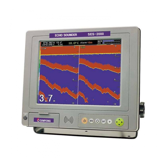
Page 10: Echo Sounder Screen
3.1 Echo Sounder Screen ② ① ③ ④ ⑤ ⑥ ⑦ ⑧ ⑨ ⑩ ① Ownship Lat/Long : Lat/Long of Ownship position(Present) in case of being connected by ex. data ② Temperature : Present temperature measured by thermometer(in connected thermometer) ③... -
Page 11: Key And Operation
3.2 Key and Operation ECHO SOUNDER SES-2000 POWER Power ON/OFF. ON : Holding press 1 sec OFF : same way about 2sec. Selecting menu. Changing display mode. Stop alarm or select/change items in menu. Press cursor to show changeable rod. Press one more time it is dispeared. Highlighted cursor. -
Page 12: Menu
3.3 Menu 1. Echo Sounder 1. Frequency 2. Nav Data 1. Data Output 2. TX Power 2. Depth Output 3. Pulse 4. Depth 5. Printer On 6. Depth Alarm 7. Disp Temp. 8. Auto Depth 9. Depth Unit 10. Erase Noise 11. -
Page 13: Screen Mode
3.4 Screen Mode The display provides a different screen each function, Press to select a screen mode. Switching Turn of Screen mode Dual Freq. High Freq. Low Freq. High/Expansion Low Freq. replay High Freq. replay Low/Expansion Dual Frequency In the dual frequency mode, The frequency is displayed at the top of screen in yellow letter as low/high frequency. - Page 14 High Frequency Low Frequency...
- Page 15 High Frequency - Expansion Low Frequency – Expansion...
- Page 16 High Frequency Replay Low Frequency Replay...
-
Page 17: Chapter 4: How To Control Functions
4 4 4 4 HOW TO CONTROL FUNC. This chapter is described about how to control functions. Echo Sounder Set Navigation Data System... -
Page 18: Echo Sounder Set
4.1 Echo Sounder Set The echo sounder set menu is to use advanced performance and functions thru adjusting various set values as following instruction. Select [Echo Sounder] Select [Echo Sounder] Select [Echo Sounder] Select [Echo Sounder] In order to return previous menu after set value, Press 4.1.1 Frequency The frequency set may provide you to select each high or low frequency to measure depth. -
Page 19: Transmitting Power
4.1.2 Transmitting Power Transmitting power ser is to be used setting strong(600W) or weak(300W). Example Example Example Example Select [Transmitting Power] Select [Transmitting Power] Select [Transmitting Power] Select [Transmitting Power] 4.1.3 Pulse Width The pulse width set is to be used for setting its long or short. Example Example Example... -
Page 20: Printer
4.1.5 Printer This printer function can make its depth data to print out by connected printer. Whenever pressing , Setting USE( ) / CANCEL( ) one after the other. Example Example Example Example Select [Printer] Select [Printer] Select [Printer] Select [Printer] 4.1.6 Depth Alarm The depth alarm is to make alert for the vessel who is starting to go in less depth than setting depth previously. -
Page 21: Display Temp
4.1.7 Display Temp. This function is to be used for displaying temperature when it is connected with thermometer. Whenever pressing selecting USE( ) / CANCEL( ) one after the other. It can be adjusted between -9.9℃ and +9.9℃. [◀],[▶] can adjust by 1℃ step ,[▼],[▲] can adjust by 0.1℃ step. Without temperature thermometer, It says “Error”. -
Page 22: Depth Unit
4.1.9 Depth Unit The depth unit is a function to display meter or feet by depth unit in a screen. Example Example Example Example Select [ Select [Auto Depth Select [ Select [ Auto Depth Auto Depth Auto Depth] ] ] ] 4.1.10 Noise Erase This function is to erase any noise out of input signal through transducer. -
Page 23: Screen Speed
4.1.12 Screen Speed This is a function to control updating depth data speed in a screen. As much as control bar goes to the right side, its updating speed is faster. Example Example Example Example Select Select Select Select [S.Speed] [S.Speed] [S.Speed] [S.Speed]... -
Page 24: Nav Data
4.2. Nav Data This is a function to use for setting which signal(NMEA data) is out thru port to be interfaced with external devices. Select [Nav Data] Select [Nav Data] Select [Nav Data] Select [Nav Data] To return precious menu after set, Press... -
Page 25: Data Output
4.2.1 Data Output Items in data output is generally to be used for transmitting data input by GPS receiver to external devices. In this case, the items not received by external devices will not be out even being selected output. After selecting item to be needed, Press , USE( ) / CANCEL(... -
Page 26: System
4.3. SYSTEM SYSTEM menu is used to display version, set-up brightness, and language. Eventhough this menu is not used frequently, it is used to set up functions wihich may affect the overall system. Users can set brightness, language, and depth display only. Other values can not be changed after Input when the equipment is manufactured or installed. -
Page 27: Brightness
4.3.1 BRIGHTNESS This menu is to adjust brightness. Brightness menu is the function to adjust screen brightness. Adjust proper brightness during navigation for safety. Press [▼],[▲] to select adjustment bar and press [◀],[▶] to change brightness.. Example Example Example Example Select [BRIGHTNESS] 4.3.2 Background Mode Background mode is to change background color. -
Page 28: Depth Display
4.3.4 DEPTH DISPLAY DEPTH DISPLAY is the function to set up the depth display position on the screen. Depth can be displayed on the left, center, right, and hide on the screen. Refer to the below example to understand how to change the display position.. Example Example Example... -
Page 29: Chapter 5: Installation And Maintenance
5 5 5 5 INSTALLATION & MAINTENANCE This chapter explains installation and maintenance. INSTALLATION EQUIPMENT INSPECTION & MAINTENANCE TROUBLE SHOOTING... -
Page 30: Installation
5.1 INSTALLATION Installation Please be cautious in unpacking the product to check if the contents are same as ordered. In particular, pay sufficient attention to the external look to see if there has been any damage in the course of transportation. If found, take some necessary actions for appropriate installation. In case that any on-scene action is not available, please contact us a.s.a.p for the right remedies. -
Page 31: Inspection And Maintenance/Trouble
5.2 INSPECTION AND MAINTENANCE/TROUBLE SHOOTING 5.2.1 GENERAL To maintain the originally designed functions and the life cycle, regular check and maintenance are required. As inappropriate inspection and maintenance rather deteriorate the equipment and shorten the life cycle, the following instructions should be kept in user's mind. -
Page 32: Break Down & First Aid
5.2.6 Break Down & First Aid Symptoms Details Defectives power turns on(Front LED If a buzz sound is heard LCD module or back-light module light) screen is defective displayed If a buzz sound is not heard CPU board is defective power does not turn on Check the fuse and in case of Check if it is over DC 35V or changed... -
Page 33: Checkpoints And Actions To Be Taken For Irregularities
5.3 Checkpoints and Actions to be taken for Irregularities Symptoms Checkpoints Actions √ Shaky screen Check the LCD connectors' Wash connector and boards √ White stripes contact with screen volatile cleaner √ Screen color changes √ Screen is not displayed at Check the contact status Wash connector and board power/on... - Page 35 APPENDIX APPENDIX 1. PACKING LIST APPENDIX 2. INSTALLATION DRAWING...
-
Page 36: Appendix 1. Packing List
SCN-20-2P CABLE CODE NO. SCN-16-4P DATA CABLE CONNECTOR CODE NO. ACC-CNT-001 Ø4 × 16 SCREW CODE NO. SPR-1407 KIV 5.5 ㎟ GROUND CABLE CODE NO. SPR-1408 FUSE CODE NO. ACC-FUSE-001 DACT-300 CABLE TIE CODE NO. INSTRUCTION MANUAL CODE NO. SES2000-MK... - Page 37 SES-2000/SES-2000N (2/2) ITEM DESCRIPTION MODEL Q’ty CHK REMARK 6P.SHIELD CABLE/10M Remote Depth Option Indicator cable CODE NO. ACC-CAB-003 SCN-16-6P 50KHz Rubber SCN-20-6P CODE NO. TD-22 50KHz Book Transducer Option (SES-2000 CODE NO. TE-2000-5 Option 200KHz Rubber / SES-2000N Standard) SCN-20-6P CODE NO.
-
Page 38: Appendix 2. Installation Drawing
APPENDIX 2. INSTALLATION DRAWING...
Need help?
Do you have a question about the SES2000 and is the answer not in the manual?
Questions and answers