Table of Contents
Advertisement
Quick Links
Download this manual
See also:
Owner's Manual
Advertisement
Table of Contents

Related Manuals for Haier TDVCF2016


Summary of Contents for Haier TDVCF2016
-
Page 1: Colour Television
COLOUR TELEVISION SERVICE MANUAL Models TDVCF2016 ● Features ● 51CM pure flat picture tube ● CCD function ● 181 program presetting and memory ● Parental control ● Inner DVD ● Inner VCR ● AV stereo and MTS TV-8888-69 0/54... -
Page 2: Table Of Contents
Color Television Model:20S62(TDVCF2016) CONTENTS Product Code illumination and Series Introduction --------------------2 Features --------------------------------------------------------------------------------3 Specifications-------------------------------------------------------------------------4 Safety Precautions-------------------------------------------------------------------5 Warning and Cautions--------------------------------------------------------------6 Net dimension------------------------------------------------------------------------12 Parts and Functions----------------------------------------------------------------13 Remote Controller Functions----------------------------------------------------14 Maintenance Service --------------------------------------------------------------16 Circuit Diagram-----------------------------------------------------------------------22 Circuit Explanation------------------------------------------------------------------23 Adjustment-----------------------------------------------------------------------------28 1/54... -
Page 3: Product Code Illumination And Series Introduction
Color Television Model:20S62(TDVCF2016) Product Code illumination and Series Introduction 20 S 62 Model series of aspect number VCR/DVD/TV combine CRT size(unit:inch) 2/54... -
Page 4: Features
Color Television Model : 20S62(TDVCF2016) Features MODEL:20 MODEL:20S62 FUNCTION FUNCTION ITEM ITEM America America PICTURE SOFTWA × M ain IC LA76834 Digital curtain Pure flat × C RT Slow fading on & off √ NTSC C olor system Semitransparent menu ×... -
Page 5: Specifications
Specifications Color Television Model:20S62(TDVCF2016) Specifications POWER SUPPLY: AC 120V, 60 Hz Tuning system: FS tuner IF: 45.75MHz Power consumption: 100W Antenna input impedance: 75Ω Receiving system: a) Color system: NTSC b) Broadcast TV system: M Language displayed: English/French/Spanish Video input: 1.0V (75Ω) -
Page 6: Safety Precautions
Safety Precautions Color Television Model:20S62(TDVCF2016) Safety Precautions IMPORTANT SAFETY NOTICE Many electrical identify these parts and mechanical parts in this chassis have special safety-related characteristics! In the Schematic Diagram and Replacement Parts List. It is essential that these special safety parts should be replaced with the same components as recommended in this manual to prevent X-RADIATION, Shock, Fire, or other Hazards. -
Page 7: Warning And Cautions
Color Television Model:20S62(TDVCF2016) Warning and Cautions 1. When you clean the TV set, please pull 4. To prevent the TV set from firing and out the power plug from AC outlet. Don't electric shock, don't clean the cabinet and the screen with make the TV set rain benzene, petrol and other chemicals. - Page 8 Color Television Model:20S62(TDVCF2016) Remember: Safety First. General Servicing Precautions 1. Always unplug the receiver AC power cord from the AC power source before: a. Removing or reinstalling any component, circuit board module or any other assembly of the receiver. b. Disconnecting or reconnecting any receiver electrical plug or other electrical connection.
- Page 9 Color Television Model:20S62(TDVCF2016) Some semiconductor (solid state) devices can be damaged easily by static electricity. Such components are usually called Electrostatic ally Sensitive (ES) Devices. Examples of typical ES devices are integrated circuits and some field effect transistors and semiconductor “chip”...
- Page 10 Color Television Model:20S62(TDVCF2016) 5. Use the following unsoldering technique a. Allow the soldering iron tip to reach normal temperature. (500 F to 600 b. Heating the component lead until the solder melts. c. Quickly draw the melted solder with an anti-static, suction-type solder removal device with solder braid.
- Page 11 Color Television Model:20S62(TDVCF2016) Bend into a “U” shape the replacement transistor leads. Connect the replacement transistor leads to the corresponding leads extending from the circuit board and crimp the “U” with long nose pliers to insure metal to metal contact then solder each connection.
- Page 12 Color Television Model:20S62(TDVCF2016) 1. Carefully remove the damaged copper pattern with a sharp knife. (Remove only as much copper as absolutely necessary). 2. Carefully scratch away the solder resist and acrylic coating (if used) from the end of the remaining copper pattern.
-
Page 13: Net Dimension
Color Television Model:20S62(TDVCF2016) 5. Net dimension The Net dimension(MM) is 570*480*510. 12/54... -
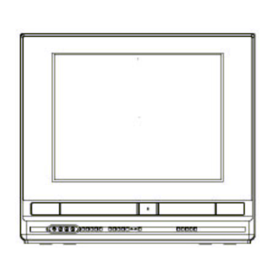
Page 14: Parts And Functions
Color Television Model:20S62(TDVCF2016) Parts and Functions (1). Front panel of the TV set (2). Rear panel of the TV set 13/54... -
Page 15: Remote Controller Functions
Color Television Model:20S62(TDVCF2016) Remote Controller Functions 14/54... -
Page 16: Maintenance Service
Color Television Model : 20S62(TDVCF2016) Maintenance Service and Trouble shooting A. Principle integrated circuits A1.20S62 color TV set composed of the following sections position specification model supplier I801 SanKen power IC STR-W6735 T804 power switching transformer Ningbo Lishunda BCK-08A6F-3 T401... - Page 17 Color Television Model:20S62(TDVCF2016) 16/54...
- Page 18 Color Television Model:20S62(TDVCF2016) 17/54...
- Page 19 Color Television Model:20S62(TDVCF2016) 18/54...
-
Page 25: Circuit Explanation
Model : 20S62(TDVCF2016) Color Television Circuit Explanation 1. Definition and voltage of every pin on every IC. Measure condition: picture is Philips color round; Brightness and contrast is 42; Sound is music; Volume is 20; Use FLUKE 17B, DC voltage. - Page 26 Model : 20S62(TDVCF2016) Color Television CVBS decoding and TV IC: LA76834 Pin definition Voltage(V) remark F.GND F.GND F.GND F.GND IF GND IF VCC 4.82 FM Filter 1.906 AFT Output 2.158 To Pin 9 of M37760 Bus Data 3.32 The first bus Bus Clock 3.60...
- Page 27 Model : 20S62(TDVCF2016) Color Television F.GND F.GND F.GND fsc(3.58MHz) output 2.397 Not used Chroma APC Filter Clamp Filter 1.81 Y Filter 3.58MHz Crystal input Connect to GND Selected Video Output 2.77 Not used Video/Chroma/Vertical GND Connect to GND External Video input(Y in) 2.94...
- Page 28 Model : 20S62(TDVCF2016) Color Television (5) sound process IC: TDA7449 Pin definition Voltage(V) remark 4.51 CREF 8.98 From SW+9V PGND 3.79 ROUT 3.79 LOUT Not used R_IN2 R_LN1 L_IN1 Not used L_IN2 MUXOUT(L) 4.53 MUXOUT(R) 4.53 BIN(R) BOUT(R) BOUT(L) BIN(L)
- Page 29 Model : 20S62(TDVCF2016) Color Television (7) VCR decoding IC: LA71207 Pin definition Voltage(V) remark VREF 2.3V audio line amp PB in EQ AMP Receive normal sound signa l from VCR and send it to P6 o f PB.EE ( A.HEAD PLAYBACK )...
- Page 30 Model : 20S62(TDVCF2016) Color Television SW +5V 4.86 CCD VCC CPU +5V 320FH VCO 3.58M crystal input VX01 REC APC SW +5V C Vcc The first bus The first bus Connect to P73 of M37760 VCR CS C GND Connect to P15 of M37760...
- Page 31 Model : 20S62(TDVCF2016) Color Television (8) switching of CVBS signal and sound signal IC: MM1492 Pin definition Voltage(V) remark 4.86 Front AV VIDEO input V1-V 0.039 Front AV AUDIO L input V1-L Not used V1-Y Front AV AUDIO R input V1-R 4.85...
- Page 32 Model : 20S62(TDVCF2016) Color Television (9) Hi-Fi decoding and MTS IC: LA72670 Pin definition Voltage(V) remark Send VCR AUDIO L signal to P14 Line mute terminal ( L) of MM1492 2.55 Not used 8.86 SW +9V MUTE 4.86 SW +5V 1.91...
- Page 33 Model : 20S62(TDVCF2016) Color Television R-CH PNR R-CH PNR R-CH PNR R-CH PNR/NR waiting DET terminal(L) SW +5V 4.86 HI-FI input terminal(R) input changeover switch output(L) Connect to P26 of M37760 A.MUTE A.GND Ripple filter stereo PLL filter SW +9V 8.86...
- Page 34 Model : 20S62(TDVCF2016) Color Television (10) CPU of the whole set: M37760(M37762 after MASK) Pin definition Voltage(V) remark 4.84 VCR key KEY1 4.84 DVD key KEY2 0.023 Not used 4.69 Connect to adjustment small board PATH ADJ. 0.973 Connect to P40 of LA72670...
- Page 35 Model : 20S62(TDVCF2016) Color Television 0.012 CLK SEL 4.84 OSD IN 2.290 2.289 OSD OUT Connect to GND 0.007 1.390 0.004 0.007 OSD GND 2.664 0.031 0.040 CPU +5V OSD VCC 4.79 1.971 V HOLD 1.501 Come from P26 of LA71207 2.007...
- Page 36 Model : 20S62(TDVCF2016) Color Television Connect to S203 4.84 REC.SAFE.SW Connect to P204 of VCR CAP FG 2.42 AMP GND 0.011 0.011 DRUM FG Connect to P204 of VCR DRUM PG/FG AMP REF.OUT 2.429 2.425 AMP REF.IN CTL(-) CTL(+) 2.386 2.399...
- Page 37 Color Television Model:20S62(TDVCF2016) 2. curcuit explanation (1)power curcuit In this set, the power curcuit uses STR-W6735, which is produced by Fairchild Company. AC 120V voltage is input through the power line and goes through power filter L801 to the commutating bradge curcuit. After commutated by D801\D802\D803D\D804, the DC voltage is got by C804.
- Page 38 Color Television Model:20S62(TDVCF2016) sound amplifying VCC. If the +12V is not available at P805, the sound out of speakers will be very small in DVD mode. (3) degaussing curcuit At P806 on the power board, there is a RLY.ON signal. After POWER ON by remote controller, there will be a high voltage on the RLY.ON.
- Page 39 Model : 20S62(TDVCF2016) Color Television Tuner U101 outputs the IF signal and U102 is the SAWF. After U102, the IF signal is send to P78 and P79 of LA76834. LA76834 outputs the television signal at P56. After ceramic trap X4.5M, the CVBS signal of TV mode is formed.
- Page 40 Color Television Model:20S62(TDVCF2016) After controlled by IIC bus, MM1492 will selected the TV out signal at P42/43 and outputs it at P36/35. Mono sound signal is send to P8/7 of TDA7449. TDA7449 is controlled by IIC bus. The BASS\TRABLE\BALANCE data is send to it by M37762. When it sends out the L/R signal at P5/4, the sound signal has been dealt with.
- Page 41 Color Television Model:20S62(TDVCF2016) The width is 1mm. It is used for normal audio signal. The width is 10.7mm. It is used for video signal and HiFi sound signal. The width is 1mm. It is used for CTL signal. The width is about 5um. It is used for HiFi audio signal.
- Page 42 Color Television Model:20S62(TDVCF2016) The picture process is the same as (c). SIF signal is send to P57 of LA72670. LA72670 can adjust it is a mono signal or stereo signal or sap signal. After inner decoding, LA72670 will outpus the L and R sound signal at P78 and 80.
-
Page 43: Adjustment
Color Television Model:20S62(TDVCF2016) Adjustment A. Factory adjustment information Method to enter the factory mode:press POWER to let the set go to STANDBY mode,then press DISP\MUTE\PICT\INPUT in turn. The set will be turned on and enter the factory mode. Press the UP and DOWN keys besides PLAY/ENTER to select the item, then press LEFT and RIGHT keys to enter the selected item. - Page 44 Color Television Model:20S62(TDVCF2016) (3). GEO - Receive cross-hatch pattern. - Select GEO mode. a. H-CENTER - Select H.CENTER, adjust that data to obtain proper horizontal centering b. V-CENTER - Select V.CENTER, adjust that data to obtain proper vertical centering c. V-SIZE - Select V.size, adjust that value to proper vertical size.
- Page 45 Color Television Model:20S62(TDVCF2016) D. VCR adjustment Tools for adjustment: special tape SN-2; 1 cross screwdriver with out magnetism and 1 normal screwdriver with out magnetism; 1 oscillograph and 2 probes; 1 special PCB board(named JIG) only for VCR adjustment. 1 AV line(RCA terminal) Connect the JIG to P208 on the main board.
- Page 46 Color Television Model:20S62(TDVCF2016) (3) adjust VCR sound output. Azimuth Connect the RCA line to the rear audio output terminal. Connect the CH2 on the oscillograph to the RCA line. Adjust Azimuth to let the signal on the CH2 biggest. (4) adjust SERVO/SYSCON to 6.5H.
Need help?
Do you have a question about the TDVCF2016 and is the answer not in the manual?
Questions and answers