Table of Contents
Advertisement
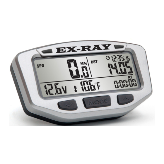
EX-RAY
Digital Speedometer Panel With Voltage
Meter for Golf Carts, NEV, Conversions
USER's MANUAL
SPEED | DISTANCE | TEMP | CLOCK | BATT VOLTAGE
"An Aftermarket solution
for Electric Vehicles used
on-road or off-road"
Advertisement
Table of Contents

Summary of Contents for EDT EX-RAY
- Page 1 EX-RAY VOLTAGE Digital Speedometer Panel With Voltage Meter for Golf Carts, NEV, Conversions USER’s MANUAL SPEED | DISTANCE | TEMP | CLOCK | BATT VOLTAGE “An Aftermarket solution for Electric Vehicles used on-road or off-road”...
- Page 2 Short Cuts Normal Mode: = Activate backlight manually = Switch between screens in normal mode = Start or stop the stop watch Data Setting Mode: = Enter data setting mode = Switch between screens in data setting mode = Scroll through current data setting = Move to next digit of current data setting Data Reset: = Reset single-ride data...
-
Page 3: Table Of Contents
> Screen 1-2-3, Sleep Mode, Reset data screens EX-RAY Features > Explanations of all screen data, settings, functions Troubleshooting / FAQ’s Inch to Metric Tire Size Conversion Chart Glossary EX-RAY Model Numbers, Kits, Replacement Parts EX-RAY USER Setup notes and battery change dates Warranty Statement... - Page 4 EX-RAY™ Display. Note: This Manual intended as guide to proper installation but cannot predict every possible applica- tion. Some modifications may be required. EX-RAY™ is a trademark of the Energy Design Tek LLC Company Oregon USA Please Record Important Information:...
- Page 5 • When installing EX-RAY™, process. turn the vehicle power off (or ignition switch off); the • Use EX-RAY™ only for its wires carry power from the intended purpose. vehicles battery. • To reduce rick or injury, do •...
-
Page 6: Specifications
Specifications... - Page 7 Specifications...
-
Page 8: Overview
Remote Switch (optional): • The optional remote switch (sold separately) may be required when access to the display buttons is not pos- sible. Contact EDT llc for more information. (This is not a standard option and special order only) Amber... -
Page 9: Display Backlight
Display Backlight will light up with all five backlight LED’s • EX-RAY will remain lit as long as it senses wheel move- ment. After 20 minute of inactivity, EX-RAY shuts off the backlight. Press any button, roll the wheels, turn on... - Page 10 Mounting Holes Internal Battery: • EX-RAY has an internal non-rechargeable Lithium watch type battery (#CR2032). The computer can be run from the internal battery without external connection to vehicle power source. • To change the battery, unscrew the battery cap on the back oft he computer with a coin.
-
Page 11: Installation
Installation Unpacking the Display: Carefully remove the display from the packaging and verify all the parts are included for your application. Carefully remove the EX-RAY cardboard TRAY from the box. Be careful not to damage the rear mounted connectors. A sheet included will list the com- ponents included in this kit. -
Page 12: Parts Breakdown
Installation Parts PARTS BREAKDOWN: The kit includes the following: 1) 6MMx12MM Metric Magnetic bolt mounts on the front DRIVERS side wheel HUB with bracket and clamp. (In- stall sheets may detail drilling the hub) 1) Speed Sensor that mounts on the AXLE (either a 65”... -
Page 13: Display Installation
Display Installation STEERING COLUMN MOUNTS: Most installations will be on the Golf Cart Steering column using the either the universal mount EXRAY-UBOLT, or optional CNC 6061-T6 Aluminum bracket EXRAY-MEZ. (Optional dashboard mounting will include separate installation instructions). Universal Bracket Mount EXRAY-UBOLT EXRAY-UXRT The UBM will fit on all column... - Page 14 Display Installation Universal Bracket Mount: Lay a soft cloth on the work surface and lay the display face down. In- stall the Display using the two 4mm x 12mm Allen head screws. Notice the red flat back is the bump stop, the screws will stop when fully compressed.
- Page 15 Display Installation CNC Bracket Mount: Steering tube column diameters vary between golf cart manufac- turers, ensure you have the correct diameter before starting the project. (Example: the 1.50” EZ-Go tube uses 1.51” Clamp) MODELS: • EXRAY-MEZ EZ-Go 1.51” • EXRAY-MEZ-EZ RXV 1.59” •...
- Page 16 Display Installation CNC Bracket Mount: Lay a soft cloth on the work surface and lay the display face down. In- stall the Display using the two 4mm x 12mm Allen head screws. Notice the red flat back is the bump stop, the screws will stop when fully compressed.
- Page 17 Note: Some stainless steering cov- ers differ in size. The tube may need to be cut to allow the EX-RAY to fit directly onto the steel steering column. Measure tube diameter.
-
Page 18: Temp Sensor Mount
Temp Sensor Installation Temp Sensor Mount: Electric Motor: Two options: 1) Motor field coil bolt or secure using the included Aluminized tape. (Both methods shown) Gas Engine: 10mm bolt (optional water jacket sensor avail- able, contact your dealer for more info). ELECTRIC MOTOR: The temperature sensor monitors the field coil tem-... - Page 19 GAS ENGINE Temp Sensor Installation The Golf Cart gas engine Temp Sensor: The typical installation is for Air Cooled engines. Cylinder Head temperature is most critical. Oil temperature is also a good indicator. Find a location that a bolt can safely be removed and temp sensor can be installed.
- Page 20 Temp Sensor EXTENSION Installation Temp Extension Cable: Install and use the supplied cable ties to secure the 6 foot temperature extension cable. Ensure the connectors are securely attached, do not apply any stress on the wires as the motor moves up and down. INSERT THE TAPE THE SPLIT LOOM CONNECTORS...
- Page 21 Temp Sensor EXTENSION Installation Temp Sensor Extension Cable: The cable routes to the Digital Speedometer display through the front floor board. Golf Cart Models vary, pictures below are typical - your cart may look different. ELECTRIC MOTOR: Route the cable through an opening through the steering column opening.
- Page 22 SPEED Sensor BOLT Installation 10mm BOLT SPEED Sensor Installation (Most all): Speed sensor is a magnet and wheel speed sensor. The sensor mounted on the steering knuckle and magnet on the rotating wheel. Various small brackets are supplied best suit your applica- tion.
- Page 23 SPEED Sensor BOLT Installation BOLT SENSOR - AXLE Mount (Most all): Locate the appropriate bracket with 10mm hole with two 10mm JAM nuts. Various brackets used for different golf carts and steering arm knuckles. (Lifted EZ-GO Shown) CAUTION: THE CABLE MUST NOT CONTACT THE MOVING STEERING KNUCKLE!
- Page 24 SPEED Sensor BOLT Installation BOLT SENSOR-AXLE Mount (Most all): Route the cable to prevent contact with the wheel. The full LEFT and full RIGHT turn stops should be checked to ensure the cable is not pinched, binds, or rubs. CAUTION: THE CABLE MUST NOT CONTACT THE MOVING STEERING KNUCKLE OR TIRE! Secure the cable with cable clamps.
- Page 25 SPEED Sensor BOLT Installation BOLT SENSOR - YAMAHA G2-G22-DRIVE, EZGO SHORT HUB AXLE Mount: The short hub axles (with BLACK bearing cap) have no room to mount the 6mm magnet sensor with a clamp. YAMAHA G2-G19 Shown (YAMAHA G22-DRIVE Similar) Either replace with aftermarket bear- ing hubs - or use the “magnet exten- sion bracket”...
- Page 26 SPEED BOLT Sensor Installation BOLT SENSOR - YAMAHA G2-G22-DRIVE, EZGO SHORT HUB AXLE Mount: Use a 13/64” (5mm) Drill Bit (no larg- er than 7/32” or 5.5mm) to drill a pilot hole at 2.4” (61mm)from left edge - drill BETWEEN THE LINES marked earlier.
- Page 27 SPEED BOLT Sensor Installation BOLT SENSOR - YAMAHA G2-G22-DRIVE, EZGO SHORT HUB AXLE Mount: Gather the parts for the 6mm x 19mm Mag mount. TWO 6mm nuts will be needed, 1-LOCK nut and 1-JAM nut for the magnet. YAMAHA G2-G19 Shown, newer 2003-2008 G22-2008-and up YDR DRIVE hubs are similar.
- Page 28 SPEED Sensor BOLT Installation BOLT SENSOR - CABLE INSTALL Install Magnet Page 25-27, then select your YAMAHA G2-G19, G22, Drive, and EZGO “SHORT HUB”: hub Install: SHORT AXLE SEE PAGE 29: >EZGO “SHORT HUB” 2008+ Driver Knuckle PN#607413 (or similar) >EZGO MED-TXT 2001-UP...
- Page 29 SPEED Sensor BOLT Installation BOLT SENSOR - SHORT YAMAHA G2-G19, EZGO SHORT HUB SENSOR Mount: Locate the X-90° TAB bracket Shown YAM G2-G19 as Shown YAM G22-YDR See Page: 30 Mount the Speed Sensor 10mm BOLT with two jam nuts onto the bracket, move the speed sensor so very little protrudes as shown.
- Page 30 SPEED Sensor BOLT Installation BOLT SENSOR - LONG YAMAHA G22-DRIVE LONG AXLE SENSOR Mount: Locate the LONG 90° TAB bracket YAM G22-YDR as shown YAM G2-G19 See Page 29 Mount the Speed Sensor 10mm BOLT with two jam nuts onto the bracket, move the speed sensor so 3/4”...
- Page 31 SPEED Sensor BOLT Installation BOLT SENSOR - CABLE ROUTING (ALL EZ, YAM G2 - DRIVE, etc.) Route the cable to prevent con- tact with the wheel. The full LEFT and full RIGHT turn stops should be checked to ensure the cable is not pinched, binds, or rubs.
- Page 32 SPEED Sensor BOLT Installation BOLT SENSOR - JAKE’S DISC BRAKES: (Most all models): Pictures shown off the vehicle but can be performed on the vehicle, drivers side. Mount magnet into SHORT bracket as shown and use the DISC mounting stud, hand tight for now.
- Page 33 SPEED Sensor BOLT Installation BOLT SENSOR - JAKE’S DISC BRAKES: EZGO SHOWN (others similar): Secure the cable with cable clamps. Watch for CHAFFING points that may damage the ca- ble. Always use TWO cable ties side by side (should one break in the future) CAUTION: THE CABLE MUST NOT CONTACT THE MOVING...
- Page 34 SPEED Sensor BOLT Installation BOLT SENSOR - LIFTED CLUB CAR or JAKE’S LIFT KIT / HUB AXLE Mount: The Club Car with 6 inch spindle lift, or most Jakes Lift kits with angles spindle axles require the 30’ Degree bracket (supplied). Mount the Speed Sensor 10mm BOLT with two jam nuts onto the bracket, move the speed sensor so...
- Page 35 SPEED Sensor BOLT Installation BOLT SENSOR - LIFTED CLUB CAR or JAKE’S LIFT KIT / HUB AXLE Mount: Attach cable ties to the steering arm. Rotate the steering wheel FULL LEFT and FULL RIGHT and check for binding. Route the cable as described earlier.
- Page 36 XRT-850E SPEED Sensor TAB Installation TAB SENSOR - CLUBCAR XRT-850E HUB AXLE Mount: The XRT requires a special TAB speed sensor mounted to the cast iron steering knuckle. XRT-850G (GAS) comes with its own separate instruction sheet. MAGNET MOUNT: The 6mm x 19mm magnet mount is the same as previously de- scribed.
- Page 37 XRT-850E SPEED Sensor TAB Installation TAB SENSOR Continued: Mount the TAB Speed Sensor to the supplied bracket using the two 4mm x 12mm countersunk screws with NYLOC nut as shown. Mount the bracket to the REAR WARD edge of the drivers side steering knuckle.
- Page 38 Power Wire (Optional) Installation EXTERNAL POWER WIRES: The external power cable KIT- EXRAY-PWR provides power to the backlight and two warning LED. The supplied wire must be connected to a FUSED 12-48 VOLT CIRCUIT. (Cable assem- bly may vary from photo). This circuit is best connected to the KEY SWITCHED power, when turned off disables the...
- Page 39 The wires are routed along the TOP of the steering column. A optional protection tube cov- ers the wires and offers a clean installation look. EDT llc MODEL: HDW800-006-CPT Carefully attached all the con- nectors. Make sure the fragile wires are NOT STRESSED.
- Page 40 Tire Wheel Size Calculation Calculating Proper Tire Size: Four methods to set the proper size which determines speed. The number needed in the com- puter is in millimeters. Method 1) Easy Ruler Method: Find the circumference of the front wheel by measuring its diameter in millimeters.
- Page 41 Tire Wheel Size Calculation Method 3) Distance Measurement: For the most accurate measurement, use wheel size measure- ment from Method 2 or set the wheel size to 1700 for lifted carts (20-22 inch tires) and 1435 for stock 18 inch wheels. 1.
- Page 42 Tire Wheel Size Calculation Method 4) Tire Chart Quick Set: The chart below picks typical tire sizes and performed calcula- tions. This is a reference and if accurate data is required, or speeding tickets can be issued, the previous methods 1-3 must be used.
- Page 43 Battery Voltage (12, 24, 36, and 48V systems) After setting is confirmed, EX-RAY will move on to the next set- ting in order. If no button is pressed for 15 seconds, EX-RAY will return to Normal Mode. Enter Data Setting Mode: >...
- Page 44 Program Kilometers or Miles Per Hour: To cycle between KMH and MPH press the left button. TO CONFIRM PRESS THE CENTER BUTTON. EX-RAY will go to the next screen Program Wheel size: See “Measuring Wheel Size” section for more information.
- Page 45 Data Setting Program 12 or 24 Hour Clock: EX-RAY factory default is 12 hour format.. TO CYCLE BETWEEN 12 AND 24 HOURS, PRESS THE LEFT BUTTON TO CONFIRM PRESS THE CENTER BUTTON. EX-RAY will go to the next screen Program Time of Day:...
- Page 46 TO CYCLE BETWEEN °C or °F HOURS, PRESS THE LEFT BUTTON TO CONFIRM PRESS THE CENTER BUTTON. EX-RAY will go to the next screen Program HIGH Temperature Warning: As motor temperature sensor (Electric or Gas) reaches the value of this setting, the Amber left LED will turn on as a CAUTIONARY warning.
- Page 47 MODIFY FLASHING DIGITS BY PRESSING THE LEFT BUTTON. CHANGE TO NEXT DIGIT BY PRESSING RIGHT BUTTON. TO CONFIRM PRESS THE CENTER BUTTON. EX-RAY will go to the next screen Electric Motors: (Typical Settings - do not exceed 85°C) • WARNING: 65°C (149°F) •...
- Page 48 Set check the oil or add water to the batteries in an electric cart. Set the number of miles or kilometers left until EX-RAY displays the the number of miles or kilometers left until EX-RAY displays the oil and wrench shaped reminder icons.
- Page 49 Setting to 0 disables the alert. (Factory default = 0 no warning) MODIFY FLASHING DIGITS BY PRESSING THE LEFT BUTTON. CHANGE TO NEXT DIGIT BY PRESSING RIGHT BUTTON. TO CONFIRM PRESS THE CENTER BUTTON. EX-RAY will go to the next screen.
- Page 50 Setting to 0 disables the alert. (Factory default = 0 no warning) MODIFY FLASHING DIGITS BY PRESSING THE LEFT BUTTON. CHANGE TO NEXT DIGIT BY PRESSING RIGHT BUTTON. TO CONFIRM PRESS THE CENTER BUTTON. EX-RAY will go to the next screen.
- Page 51 MODIFY FLASHING DIGITS BY PRESSING THE LEFT BUTTON. TO CONFIRM PRESS THE CENTER BUTTON. EX-RAY will go to the next screen. DST Distance Resolution Distance resolution can be set in 1 or 2 place decimal. (Note: The speed sensor utilizes only one magnet and resolution does not increase accuracy at speeds below 2 miles per hour).
- Page 52 NORMAL MODE SCREENS Switch between 3 Normal Mode Screens: All of the information the EX-RAY provides is on one of these 3 screens. When driving, the user has the choice of staying on screen 1 or screen 2. Screen 3 will default back to screen 1 after 5 seconds.
- Page 53 Normal Screen Modes SCREEN 2: Screen 2 displays: • Speed (SPD) • Distance (DST) • Battery Voltage (V) • Air temperature • Stop Watch (TT) • Time of Day SCREEN 3-A: Screen 3-A displays: • Avg Speed (AVG S) • Odometer (ODO) •...
-
Page 54: Sleep Mode
Reset single ride data to zero (distance traveled) Sleep Mode: If EX-RAY receives no data for 20 minutes (either wheel data or a button pressed), it will enter Sleep Mode. It will only display the clock while in Sleep Mode. It will exit Sleep Mode when it... - Page 55 EX-RAY Features Speedometer: The speedometer shows vehicle speed. DESCRIPTION: EX-RAY also shows average and maximum speed since last reset. Speed is displays top left of SCREEN 1 SPEED: from 0-399.9 M/H or KM/H. The SPD Icon and M/H or KM/H will also appear next to the speed reading.
- Page 56 EX-RAY Features Odometer: The Odometer shown on SCREEN 3 will DESCRIPTION: provide the user with a numeric display of total accumulated distance in miles or kilo- meters. The odometer is not re-set able. Trip Distance Meter: The Trip “DISTANCE” Meter shows how...
- Page 57 EX-RAY Features Voltage: The Volt meter shown on SCREEN 1 o& 2 DESCRIPTION: will provide the user with a numeric display of the actual battery voltage. For gas powered vehicles, the 12V alterna- tor, battery, and electrical health can be monitored.
- Page 58 EX-RAY Features Voltage: The Volt meter MIN-MAX is shown on DESCRIPTION: SCREEN 3 will display minimum or maxi- mum BATTERY VOLTAGE cycling every other second. For gas powered vehicles, low voltage indi- cates the lowest level reached or alternator problems. Electric vehicles displays battery pack lowest level under load.
- Page 59 EX-RAY Features Clock and Stop Watch: The Time of Day Clock is displayed in the Time of Day bottom right corner in all screens next to Clock: the Clock Icon and during sleep mode. The clock is displayed in either 12H or 24H format.
- Page 60 (Valuable for accounting for battery life time in EV or Gas Engine overhaul data) DISPLAY: The highest Accumulated Ride Time EX-RAY can display is 9999.59 hours (When the maximum value is reached, EX-RAY will not roll the number back to 0).
- Page 61 EX-RAY Features Ambient Air Temperature / Motor-Engine Temp: EX-RAY displays different temperature information on each of the three normal mode screens. SCREEN 1: Electrical Motor / Gas Engine Temperature SCREEN 2: Air (Ambient) Temperature SCREEN 3: Maximum Electric Motor / Gas Engine temperature received by the sensor since the last reset.
- Page 62 LEFT and CENTER buttons for 3 seconds. EX-RAY MUST BE RESET TO RECOGNIZE SENSORS: • If ANY wires become unplugged from EX-RAY, do a reset after everything is re-connected. (Power wire not included) • Alternately, push RED RESET button on the back of the...
-
Page 63: Frequently Asked Questions
The wheel size setting may be incorrect. Please review wheel size measurement instructions section. EX-RAY is not displaying information correctly. • If the wires on the back of the EX-RAY become damaged, incorrect readings may be displayed. • Avoid twisting, crimping, kinking, or otherwise abusing the wires. - Page 64 • To replace the battery, use a small coin to unscrew the round panel on the back of the EX-RAY. Remove and properly dispose of the spent battery. Install a new battery of the same make. Make sure the POSITIVE POLE IS FACING UP.
-
Page 65: Wheel Size Calculator
Inch to Metric Tire Size: The following chart is calculations for tire size in mm entered into the EX-RAY. The tire size may vary with tire pressure, vehicle weight changes, etc. Use this chart for a starting reference. For more accurate speed measurements, utilize the methods de- scribed “Wheel Size Calculator”... -
Page 66: Data Setting Mode
12, 24, 36, and 48Volt dc battery systems. Do not exceed 60VDC at any time. DATA SETTING MODE: The place to set EX-RAY’s settings. Includes distance units, wheel size, clock format, time, tempera- ture units, high temp setting, over temp setting, and oil/battery maintenance reminders. -
Page 67: Glossary
EX-RAY wheel data. A second temperature sensor provides criti- cal motor temperature information to the driver. SLEEP MODE: If EX-RAY does not receive any sensory infor- mation, it will go into sleep mode and only display to the clock. SPEED (SPD): The current speed the vehicle is traveling. - Page 68 EXRAY MODEL NUMBERS: MODEL DESCRIPTION EXRAY-UBOLT EXRAY display Univer- Fits most all vehicles sal mount, 10mm BOLT Speed Sensor EXRAY-UBOLT-EZ-RXV EXRAY display Univer- RXV AXLE ONLY sal mount, 10mm BOLT Speed Sensor EXRAY-UBOLT-JAKES- EXRAY display Univer- sal mount, 10mm BOLT Jakes Disc ONLY Speed Sensor EXRAY-UXRT-850E...
- Page 69 EXRAY MODEL NUMBERS: MODEL DESCRIPTION EXRAY-MEZ EXRAY Display, CNC EZGO 1.51” Steering Machined mount, 10mm column Diameter BOLT Speed Sensor EXRAY-MEZ-RXV EXRAY Display, CNC EZGO 1.59” Steering Machined mount, 10mm column Diameter BOLT Speed Sensor EXRAY-MCC EXRAY Display, CNC ClubCar 1.66” Steer- Machined mount, 10mm ing column Diameter BOLT Speed Sensor...
- Page 70 EXRAY MODEL NUMBERS: MODEL DESCRIPTION EXRAY DISPLAY Replacement digital display head KIT-EXRAY TEMP ASY200-003-CHT, 10mm Temp sensor, ASY200-005-TMP, 72” extension cable KIT-EXRAY PWR Cable Power kit, 48” KIT-SPD BOLT Speed BOLT Sensor Kit, 65” cable 10mm KIT-SPD TAB Speed TAB Sensor Kit, 65” cable, XRT KIT-EX-RXV BKT RXV-Axle 10MM BOLT Bracket &...
- Page 71 Its a good idea to write down date of installation, mainte- nance, battery changes, miles per year, TIRE SIZE, or any settings that may help in the future to setup your EX-RAY. Battery CR2032 Date: Tire Size Vehicle Setting #...
-
Page 72: Limited Warranty
EX-RAY LIMITED WARRANTY Within 1 year from the date of purchase, EDT LLC, Will repair or replace, at it’s option, any EX-RAY™ which is deemed defective in workmanship or materials. Please contact the dealer where the EX-RAY™ was purchased for assistance. Retain Proof Of Purchase.
Need help?
Do you have a question about the EX-RAY and is the answer not in the manual?
Questions and answers
How to change speedometer from metric to yards?
The EDT EX-RAY speedometer does not support changing the unit to yards. It allows switching between miles per hour (mph) and kilometers per hour (km/h) only. To change between these, enter data mode, wait for "M H" to flash, then press the button to toggle between mph and km/h.
This answer is automatically generated