
Related Manuals for ESP Varimax 20 ASHP

Summary of Contents for ESP Varimax 20 ASHP
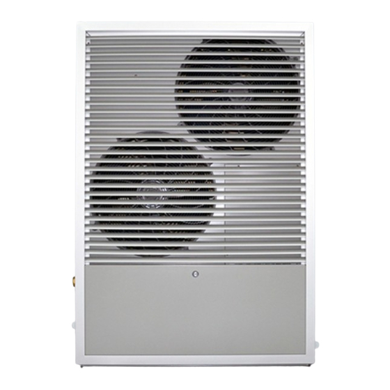
- Page 1 ESP VARIMAX 20 ASHP Installation and Operation Manual 1 of 41 www.esavep.com PASRW060-D-BP V 1.0...
- Page 2 WARNING ! READ THIS BEFORE INSTALLING THE UNIT. The installation of all un-vented water heating systems above 15 litres MUST comply with local area Building Regulations. It is a legal requirement that the local Building Control Officer be notified of any proposed installation.
-
Page 3: Table Of Contents
Contents: 1.0 Preface 1.1 Features of the Varimax 20 ASHP 2.0 Safety Precautions 3.0 Varimax 20 Specifications 3.1 Appearance 3.2 Dimensions 4.0 Choosing the right heat pump 4.1 Heat Load Calculation 4.2 Varimax 20 Output Statistics 4.3 Emitter systems 5.0 Installation 5.1 Where to use and Where to Site the unit... - Page 4 7.6 Wiring-in The Unit 8.0 Unit Specifications 9.0 Commissioning 9.1 Pre-Start Checks 9.2 Switching on the Unit 10.0 UNIT CONTROLLER 10.1 main Interface 10.2 Basic Operation 10.3 Start-UP and Shut-Down 10.4 Setting the Target Temperature 10.5 Using the Premium User Interface 10.6 Setting the Time 10.7 Setting the Timers 10.8 Cancelling the Timers...
-
Page 5: Preface
ESP will not be liable. All ESP ASHPs are covered by the warranty contained in the ESP Terms and conditions of Business a copy of which will have been provided to you prior to your purchase. -
Page 6: Safety Precautions
If you hear abnormal noises, or smell strange odours, coming from the unit, switch it off immediately and call your installer or ESP. Do NOT install the unit close to any gas fired appliance, heater or fire. -
Page 7: Varimax 20 Specifications
Ensure that you use a suitably rated circuit breaker. If in doubt, have your electrician call ESP Technical Support. Switch off the power before carrying out any cleaning and/or maintenance of the unit. -
Page 8: Dimensions
Based on the local climatic conditions, construction features and insulation levels, your system designer will calculate the heat load of your building and, therefore, the appropriate unit size for your building. ESP can provide a heat load calculation that conforms to MIS 3005. For new builds, meeting the requirements of current building regulations for insulation (or better) will help ensure that the heat load of the dwelling is kept to a minimum. -
Page 9: Emitter Systems
Microgeneration Certification Scheme website offers guidance on pipe spacing for UFH systems together with sizing consideration for fan coil units such as the ESP Thermovec and traditional wet radiators can be found. Please note that, in the case of an UFH system, the floor coverings must be chosen very carefully to ensure that the heat is not ‘trapped’... -
Page 10: Location Of The Unit
“Location of Unit”. The unit generates condensate and this should be piped away from the unit and into a suitable drain to prevent ice forming on the area around the unit. This also applies to the water resulting from a defrost cycle. -
Page 11: Plumbing Considerations
It is highly recommended that a suitably sized buffer tank be installed between the unit and the heating distribution system. Please consult your installer or ESP when considering this system design point – the right sized buffer tank can make a significant difference to the economy and efficiency of the unit and the heating effectiveness. -
Page 12: Flexi Hoses
These flexible hoses are available from ESP as part of an optional ASHP Installation Pack or individually. -
Page 13: In-Line Filter
Spirotrap Strainer 6.7 Flow Setter ESP Strongly recommend the use of a flow setter in the return pipework from the buffer to the ASHP. This will allow the system flow rate to be optimised for the individual project. -
Page 14: Electrical Connection
The Glycol must be suitable for the whole system which is why ESP can supply the ideal glycol for the Varimax as an optional extra. The following table details the volume of the glycol/water... -
Page 15: Mcb
the regions and details of the different Network Operators and you will need to follow the instruction of your local DNO. The unit power specification is stated on a label on the side of the unit. We recommend the use of a dedicated 32 Amp Type C or D MCB for connection of the power supply to the consumer unit. - Page 16 The control wire must be passed through the protective wire aperture in the unit casing and plugged into the controller socket. The power supply must go through the protective wire aperture in the unit casing and be connected securely to the terminals in the control box.
-
Page 17: Unit Specifications
Terminals 45/46 for volt free Socket for Wire connection Controller Mains power Connection The unit MUST be connected to the master thermostat within the building that controls the call for heat. If you do not have a master thermostat connected to the unit from the building, you will not meet Building Regulations. -
Page 18: Commissioning
Water Pressure Drop Water Capacity 2.44 Unit Dimensions See Drawings Unit Shipping 1050 X 510 X 1475 Dimensions Net Weight See Unit Label Shipping Weight See Package Label 9.0 Commissioning 9.1 Pre-Start Checks The following checks must be made prior to starting up the unit for the first time: ... - Page 19 The parameters of the unit controller are factory set and you must not change them without consulting your installer or ESP. The exceptions to this are the running temperature (or flow temperature) of the system and the time. However, changing the flow temperature will affect the efficiency of your system and may affect your ability to claim/continue to claim any Government grant.
-
Page 20: Unit Controller
10.0 Unit Controller 10.1 Main Interface Number Icon Function This is a multi-function button used to start the units, turn it ① On-Off off, cancel a current operation and to return to the previous menu page. Used to set the time and the optional timers. ②... - Page 21 Defrost Mode Indicates that the unit is defrosting. Inlet temperature Indicates that the inlet temperature is being displayed. Outlet Temperature Indicates that the outlet temperature is being displayed. Setting Mode Indicates that the control is in setting mode. Value Indicates that the basic display area is displaying a parameter value.
-
Page 22: Start-Up And Shut-Down
10.3 Start-up and Shut Down When the unit is in stand-by mode or has automatically gone ‘blank’, the screen is activated by pressing the on-off button. When the unit is in stand-by mode, press the on-off key and hold it for 0.5 seconds to start the unit. -
Page 23: Setting The Target Temperature
If you are considering changing this setting from that set by your installer, you should consult your installer or the ESP Technical Team first. 23 of 41 www.esavep.com PASRW060-D-BP V 1.0... -
Page 24: Using The Premium User Interface
10.5 Using the Premium User Interface The Premium User Interface is used to change the time, set (or change) timers, change from a Centigrade to a Fahrenheit display, mute the interface and check the status of the ASHP. Pressing the set button to change to the Premium User Interface. -
Page 25: Setting The Time
10.6 Setting the time: First, press the time button. The display will change and using the up and down buttons will change the ‘hours’ setting. Press the set key to save the change. Use the up and down buttons to change the ‘minutes’... -
Page 26: Setting The Timers
N.B. pressing the on-off button at any stage will cancel the changes to that stage or not pressing a button within 20 seconds will save any changes made. 10.7 Setting the timers The ASHP can be set to come on and go off again for two periods per day. -
Page 27: Cancelling The Timers
10.8 Cancelling timers To cancel a timer, enter the Premium User Interface then press the time button for 2 seconds. This will display the current ‘Timer 1 on’ setting and the time will flash. Press the set button and the ‘On 1’... -
Page 28: Checking The Status Of The Ashp
10.9 Checking the Status of the ASHP To Check the status of a parameter, press the check button whilst in the Premium User Interface. Parameter Value The display will change to parameter 1. The parameter value, the ‘val’ symbol, the parameter number and ‘param’... -
Page 29: Locking The Display
10.10 Locking the Display To lock the display, simply press and hold the on/off button for 5 seconds. The ‘lock’ symbol will appear. To unlock the display, press and hold the on-off button for 5 seconds. However, the display will automatically unlock if the unit restarts after a power failure or if a fault is reported. -
Page 30: Maintenance
11 Maintenance 11.1 Essential Checks Periodically clean the in-line filter (Y strainer or Spirotrap); this will need to be every month for the first 6 months following start up of the system to allow installation debris to be extracted. NOTE that a lack of water in the system or debris/dirt entering the system can damage the unit. -
Page 31: Troubleshooting
Please do not shut off the power supply to the heat pump in winter unless it is to be drained-down. When the air temperature is below 0°C, if the inlet water temperature is above 2°C and below 4°c, the water pump will start automatically once in every 72 hrs to provide frost protection. - Page 32 Check input current Input current over Input Over Cur. protection current Warn DC bus voltage >DC Check bus voltage Inv. DC protection bus volt Overvoltage DC bus voltage<DC Check bus voltage Inv. DC protection bus volt Lessvoltage Check current Overlarge current of the IPM Overcurrent Over Temp.
-
Page 33: Simple Faultfinding
Chip error EEPROM Error Check and change Warn the chip Weak Magnetic Comm Weak Magnetic Warn 12.2 Simple Faultfinding The following is a list of some basic faults and solutions Problem Possible Causes Suggested Solutions Heat pump will 1 Incorrect power supply. 1 Shut off th e power and check power supply. -
Page 34: Wiring Diagram
13.0 Wiring Diagram For zero volt connection from Controller 34 of 41 www.esavep.com PASRW060-D-BP V 1.0... -
Page 35: Guarantee
Practice and Regulations in force at the time of installation. ii) It has not been modified in any way other than by ESP. iii) It has only been used for the storage of wholesome water. -
Page 36: Environmental Information
This warranty/guarantee is not valid for installations outside the United Kingdom or the Republic of Ireland. Any warranty/guarantee is for replacement parts only. The purchaser of the unit acknowledges that he/she has seen ESP’s conditions of supply and has understood them. All of our units are RoHS approved units. -
Page 37: Weather Compensation
16.0 Weather Compensation The Varimax 20 has built-in weather compensation to ensure that that maximum efficiency is maintained and that output is matched to the load of the building and the external ambient temperature. With factory defaults set (it is unwise and, possibly, dangerous to change these –... -
Page 38: Performance
17.0 Performance Frequency (HZ) Frequency (HZ) Frequency (HZ) 38 of 41 www.esavep.com PASRW060-D-BP V 1.0... - Page 39 Frequency (HZ) Frequency (HZ) Frequency (HZ) 39 of 41 www.esavep.com PASRW060-D-BP V 1.0...
- Page 40 18.0 Parameter List: Please note that the changing any one of the parameters in this list may: 1. Be dangerous. 2. Invalidate the warranty on the unit. 3. Invalidate the MCS registration (where applicable). 4. Invalidate any Government grant claimed for the installation. Parameter Description Default...
- Page 41 Ambient temp electric heater start °C Electric heater delay mins You are strongly recommended to contact the ESP technical support team before changing any of these parameters. CONTACT DETAILS Earth Save Products Technical Team – 01865 598158 41 of 41 www.esavep.com...
Need help?
Do you have a question about the Varimax 20 ASHP and is the answer not in the manual?
Questions and answers