Table of Contents
Advertisement
Quick Links
Advertisement
Table of Contents

Summary of Contents for Fiberplex TIS-8632
- Page 1 USER MANUAL 6 Port 10/100/1000 Ethernet Switch TIS‐8632 ...
- Page 2 [Page Intentionally Left Blank] ...
-
Page 3: General Installation Instructions
Please consider these general instructions in addition to any product‐specific instructions in the “Installation” chapter of this manual. Unpacking Check the equipment for any transport damage. If the unit is mechanically damaged, if liquids have been spilled or if objects have fallen into the unit, it must not be connected to the AC power outlet, or it must be immediately disconnected by unplugging the power cable. Repair must only be performed by trained personnel in accordance with the applicable regulations. Installation Site Install the unit in a place where the following conditions are met: The temperature and the relative humidity of the operating environment must be within the specified limits during operation of the unit. Values specified are applicable to the air inlets of the unit. Condensation may not be present during operation. If the unit is installed in a location subject to large variations of ambient temperature (e.g. in an OB‐van), appropriate precautions must be taken. Unobstructed air flow is essential for proper operation. Ventilation openings of the unit are a functional part of the design and must not be obstructed in any way during operation (e.g. ‐ by objects placed upon them, placement of the unit on a soft surface, or improper installation of the unit within a rack or piece of furniture). The unit must not be unduly exposed to external heat sources (direct sunlight, spot lights). Ambient Temperature Units and systems by FiberPlex are generally designed for an ambient temperature range (i.e. temperature of the incoming air) of +5...+40 °C. When rack mounting the units, the following facts must be considered: The permissible ambient temperature range for operation of the semiconductor components is 0 °C to +70 °C (commercial temperature range for operation). The air flow through the installation must allow exhaust air to remain cooler than 70 °C at all times. Average temperature increase of the cooling air shall be about 20 C°, allowing for an additional maximum 10 C° increase at the hottest components. If the cooling function of the installation must be monitored (e.g. for illumination with spot lamps), the exhaust air temperature must be measured directly above the modules at several places within the enclosure. Grounding and Power Supply Grounding of units with mains supply (class I equipment) is performed via the protective earth (PE) conductor integrated in three pin Phoenix™ connector. Units with battery operation (< 60 V, class III equipment) must be earthed separately. Grounding the unit is one of the measures for protection against electrical shock hazard (dangerous body currents). Hazardous voltage may not only be caused by defective power supply insulation, but may also be introduced by the connected audio or control cables. This equipment may require the use of a different line cord, attachment plug, or both, depending on the available power source at installation. If the attachment plug needs to be changed, refer servicing to qualified personnel. ... -
Page 4: Disposal Of Packing Materials
Warranty, Service and Terms and Conditions of Sale For information about Warranty or Service information, please see our published ‘Terms and Conditions of Sale’. This document is available on fiberplex.com or can be obtained by requesting it from clients@fiberplex.com or calling 301.604.0100. Disposal Disposal of Packing Materials The packing materials have been selected with environmental and disposal issues in mind. All packing material can be recycled. Recycling packing saves raw materials and reduces the volume of waste. If you need to dispose of the transport packing materials, recycling is encouraged. Disposal of Used Equipment Used equipment contains valuable raw materials as well as substances that must be disposed of professionally. Please dispose of used equipment via an authorized specialist dealer or via the public waste disposal system, ensuring any material that can be recycled has been. Please take care that your used equipment cannot be abused. After having disconnected your used equipment from the mains supply, make sure that the mains connector and the mains cable are made useless. Disclaimer The information in this document has been carefully checked and is believed to be accurate at the time of publication. However, no liability is assumed by FiberPlex for inaccuracies, errors, or omissions, nor for loss or damage resulting either directly or indirectly from use of the information contained herein. Page 2 ... -
Page 5: Key Features
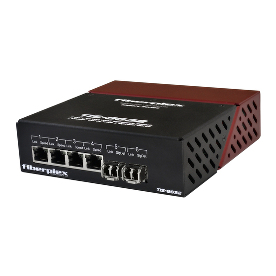
Introduction Elegantly simple yet packed with an advanced feature set, the FiberPlex Technologies TIS‐8632 is a powerful 6 Port 10/100/1000 Ethernet Switch. The unit interfaces UTP RJ‐45 jacks (x4) to variously populated SFP positions. Key Features 6 Ports – (4) 10/100/1000BASE‐T Copper and (2) 1000BASE‐X Optical Flow control for full duplex and half duplex Supports up to 10k byte JUMBO frame Supports Ports Based VLANS and TAG Based VLANS Conforms to FCC and CE codes Includes power adapter as well as a 3‐position Phoenix™ connector The TIS‐8632 is housed in the commercial ‘Throw Down’ packaging. This version is designed to be a work horse unit in various commercial and industrial environments. It is powered either by a 9VDC ‘Wall Wart’ style supply (included) or via bussed power supplied through an integrated three pin Phoenix™ connector. Up to three TIS‐8632 units can be installed in the optional 1U TDR‐01 rack shelf. Standard Ordering Options TIS‐8632‐C – Unit with no SFP modules included TIS‐8632‐L22 – Unit with (2) 1310 nm Multimode SFP modules (SFP‐MC24XC‐3131‐2) included. Conforms to IEEE 1000BASE‐LX standard. TIS‐8632‐L5B – Unit with (2) 1310 nm Singlemode SFP Modules (SFP‐SC24XC‐3131‐B) included. Conforms to IEEE 1000BASE‐LX10 standard. Getting Started Initial Inspection Immediately upon receipt, inspect the shipping container for damage. The container should be retained until the shipment has been checked for completeness and the equipment has been checked mechanically and electrically. If the shipment is incomplete, if there is mechanical damage, or if the unit fails to operate notify FiberPlex and make the shipping materials available for the carrier's inspection. Page 3 ... - Page 6 Front Indicators/Connections Figure 1 TIS‐8632 Front Face Cable Port LED, Upper Left – This LED, for each position, indicates status as per the following table; 1 Cable Port LED (Upper Left) Status Description On Link is OK Off No link present Blinking Data is being received or transmitted Ethernet Cable Port (x4) – These jacks are Unshielded Twisted Pair RJ‐45 cable connection points for 2 Cat5 capability. Cable Port LED, Upper Right – This LED, for each position, indicates status as per the following table; 3 Cable Port LED (Upper Right) Status Description 3 Blinks Repeating 1000M Speed 2 Blinks Repeating 100M Speed 1 Blink Repeating 10M Speed 4 SFP Slot (x2) – This is a standard MSA‐compliant SFP module slot. (See section ‘Inserting and Removing SFP Modules’) These ports operate only at 1000 Base‐X rates. Do not connect both SFP ports of one unit to both SFP ports of a second unit, this will cause a switching loop and the units will not operate properly. SFP Slot LED, Lower Left– This LED, for each position, indicates status as per the following table; 5 SFP Slot LED (Lower Left) Status Description ON ...
- Page 7 Rear Indicators/Connections Figure 2 TIS‐8632 Rear Face Circular DC Power Connection – DC power entry for the unit. This is a standard DC connection for use 7 with the included DC wall power supply. Phoenix™ Power Connection – Secondary power option for the TIS‐8632. This is wired in direct 8 parallel with the Circular connector and has the addition of a positive earth chassis ground connection. This can be used to power the unit on a client supplied power buss. Page 5 ...
-
Page 8: Surface Mount
Power Requirements and Mounting Flexible mounting allows the TIS‐8632 to be rack shelf mounted or used in a standalone configuration. Up to 3 TIS‐8632 units can be mounted on a TDR‐01 shelf and powered by a single, integral cable. Alternately, the TIS‐ 8632 can be used in a standalone application when paired with the included DC wall adaptor. Standalone For standalone applications, the TIS‐8632 comes with (4) peel and stick rubber feet. Simply peel the paper backing from the rubber foot and affix to four corners of the TIS‐8632. Surface Mount Surface mounting on a wall, desk, or other vertical surface can be accomplished by using either the supplied peel‐and‐stick Velcro pads, or by using the integrated keyhole mounts with the supplied wood screws. To use the wood screws: Mark the surface using the supplied template Screw the #2 ½” wood screws into the surface at each mark Leave a small amount of thread to accommodate the thickness of the TIS‐8632 case Put the large part of the keyhole over the screw head and pull to Figure 3 TIS‐8632 Surface Mount engage DIN Rail Using the TD‐DINR, the TIS‐8632 can be mounted to a DIN rail. See the TD‐DINR user manual for more details on configuration options. Mount the TIS‐8632 the TD‐DINR in the same manner regardless of the initial configuration of the mount itself or the height of top hat DIN rail utilized (35 x 7.5 or 35 x 15mm). The edge mounting solution happens to be shown below. All fasteners necessary for configuration and mounting are included with the TD‐DINR. Line up key hole on the bottom of the TIS‐8632 with the studs on the Mounting Bracket and push flat against the plate. ... - Page 9 Tray Mounting Complementing the flexibility of the FiberPlex ‘TD Series’ of fiber optic modules, the TDR‐01‐AC provides mounting, power and cable management for up to 6 modules in a compact and rugged aluminum 1U rack. The integrated key‐hole mounting holes on the bottom the TD units lock securely on mating studs while a rear retention bar holds them securely in place. A 6 position wiring harness and included power adapter provide, not just 9 VDC power, but a positive earth ground to the modules via 3 position Phoenix™ locking power connectors. Managing all that cabling and fiber can sometimes be quite a chore so an extended cabling tray with integrated tie down points are provided to help make your installation clean. **NOTE: The TDR and TDP trays use a 9VDC 3.5 Amp power adapter. When 3 TIS‐8632 are used in the same rack certain SFP populations could exceed a 3.5 Amp requirement. Please carefully check your configuration against the specification table to verify your current draw. Figure 5 TIS‐8632 installation on a TDR‐01‐AC tray Page 7 ...
-
Page 10: Handling Warnings
Inserting and Removing SFP Modules Handling Warnings SFP Modules are static sensitive. To prevent damage from electrostatic discharge (ESD), it is recommended to attach an ESD preventative wrist strap to your wrist and to a bare metal surface when you install or remove an SFP Module. Disconnect all optical or copper cables from SFP Modules prior to installing or removing the SFP Module. Failure to do so could result in damage to the cable, cable connector or the SFP Module itself. Removing and inserting an SFP Module can shorten its useful life, so you should not remove and insert SFP Modules any more often than is absolutely necessary. Protect optical SFP modules by inserting clean dust covers into them after the cables are removed. Be sure to clean the optic surfaces of the fiber cables before you plug them back into the optical ports of another SFP module. Avoid getting dust and other contaminants into the optical ports of your SFP modules, because the optics will not work correctly when obstructed with dust. Identify the Latch Type of the SFP Module SFP Modules have various latching mechanisms to secure them into the SFP Cage of a device. FiberPlex Modules can support a host of manufacturers and brands of SFP Modules so the user may encounter any number of different latches. Some of these are described below. Bail Clasp Actuator Button The bail clasp SFP module has a clasp The actuator button SFP module includes a button that you that you use to remove or install the SFP push in order to remove the SFP module from a port. This module. button can either lift ‘Up’ or press ‘In’ to release the SFP Module depending on the manufacturer. Mylar Tab Slide Tab The Mylar tab SFP module has a tab that The slide tab SFP module has a tab underneath the front of the you pull to remove the module from a SFP module that you use to disengage the module from a port. port. ... -
Page 11: Inserting A Module
Inserting a Module Attach an ESD‐preventative wrist or ankle strap, following its instructions for use. Disconnect and remove all interface cables from SFP Module. If the SFP Module has a Bail Clasp, close the Bail Clasp before inserting the SFP Module. With the gold finger connector on the bottom and the label on the top, line up the SFP Module with the empty cage and slide it in making sure that it is completely inserted and seated in the cage. Removing a Module Attach an ESD‐preventative wrist or ankle strap, following its instructions for use. Disconnect and remove all interface cables from SFP Module. Release the latching mechanism. Bail Clasp – Open the bail clasp on the SFP Module with your finger in a downward direction. Actuator Button – Gently press the actuator up (or in) while pulling the body of the SFP Module to release the SFP Module from the cage. Mylar Tab – Pull the tab gently in a straight outward motion until it disengages from the port. Make sure the tab is not twisted when pulling as it may become disconnected from the SFP Module. Slide Tab ‐ With your thumb, push the slide tab on the bottom front of the SFP module in the direction of the equipment to disengage the module from the line card port. If you pull on the SFP module without disengaging the tab, you can damage the SFP module. Grasp the SFP Module between your thumb and index ... - Page 12 Applications Page 10 ...
-
Page 13: Additional Information
Additional Information Bonding Units Two TIS‐8632 can be bonded together locally to make the equivalent of an 8 Copper x 2 fiber switch by using an SFP Passive Cable Assembly like the FiberPlex FC‐QDAXX1‐0‐0.5M. These passive cables are terminated with SFP compatible connectors and are considerably cheaper than using a pair of optical modules with a fiber jumper. The cables are only useful for short connections. In this configuration, one SFP port on each TIS‐8632 is occupied by the Passive Cable Assembly leaving one SFP port on each TIS‐8632 that can still be utilized for optical modules. This also results in 8 local 10/100/1000 copper ports. Figure 6 Representative Drawing of an SFP Passive Cable Assembly SFP MSA Compliance The SFP Multisource Agreement (MSA) is an agreement that was drafted among competing manufacturers of SFP optical modules. The SFF Committee was formed to oversee the creation and maintenance of these agreements including the SFP MSA designated as INF‐8074i. This agreement describes a mutually agreed upon standard for the form and function of SFP modules. However, not all SFPs produced are MSA compliant. The MSA provides for a transceiver (TX/RX) pinout. Other industries such as broadcast had the need for dual TX and dual RX SFP for uni‐directional applications such as video. Naturally, a non‐MSA standard was introduced allocating pinout assignments for dual output and dual input I/O configurations. In addition, the some of the internal serial communication pins were reassigned. The TIS‐8632 will only accept MSA compliant SFP modules which support a 1.25 Gbps data rate. Pinout Comparison Chart PIN Transceiver (MSA) Transceiver (Non‐MSA) Dual TX (Non‐MSA) Dual RX (Non‐MSA) 1 VEE VEE VEE VEE 2 TX_FAULT [VEE] VEE NC Rx2‐ 3 ... -
Page 14: Specifications
Specifications Figure 7 TIS‐8632 Dimensions Page 12 ... - Page 15 Copper UTP RJ‐45 Interface IEEE Standard Cable Data Rate IEEE Max Distance 10BASE‐T CAT‐3 or better 10 Mbps 100 m 100BASE‐T CAT‐5 or better 100 Mbps 100 m 1000BASE‐T CAT‐5e or better 1000 Mbps 100 m Optical SFP Interface IEEE Standard FiberPlex SFP Fiber Type λ (nm) Avg Transmitter Receiver IEEE Max Power (dBm) Sensitivity (dBm) Distance 1000BASE‐CX FC‐QDAXX1‐0‐1M Copper n/a n/a n/a 25 m 1000BASE‐SX SFP‐MC24XC‐8585‐0 Multimode ‐6 ‐18 ...
- Page 16 18040-412 Guilford Rd. • Annapolis Junction, MD 20701 fiberplex.com • clients@fiberplex.com • 301.604.0100 UMT8632 150512 ...
Need help?
Do you have a question about the TIS-8632 and is the answer not in the manual?
Questions and answers