
Subscribe to Our Youtube Channel
Summary of Contents for Gordic Environment AB PELLX
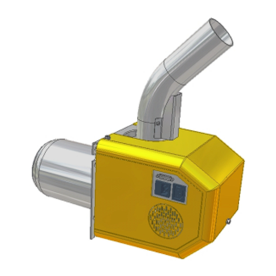
- Page 1 Installation Manual PellX 20 kW Pellets Burner Gordic Environment AB P.O Box 11, SE 280 22 Vittsjö, Sweden...
-
Page 2: Table Of Contents
1 INFORMATION ........................2 1.1 I ........................2 NTRODUCTION 1.2 T ..................3 ECHNICAL DATA IMENSIONS 1.3 D ......................4 ELIVERY CHECK 2 INSTALLATION ........................5 2.1 P ........................5 RECAUTIONS Boiler ..........................6 Chimney ..........................6 2.2 M ........................8 OUNTING General ..........................8 Burner installation......................9 Pellet storage........................9 Feed screw installation.....................10 Installation of the control box ..................11 Connection of temperature sensor..................13 Draft regulator .........................14... -
Page 3: Information
In case that you are not acquainted with the burner or if there are any other unclear questions, please contact the authorized PellX dealer for more detailed information. -
Page 4: Technical Data. Dimensions
1.2 Technical data. Dimensions Heat output, max. ___________________ approx. 20 kW Heat output, min. ___________________ approx. 13 kW Output levels ___________________ 65 %, 100 % Combustion efficiency ___________ approx. 95 % Combustion air consumption ___________ approx. 30 – 40 m Weight ___________________________ approx. -
Page 5: Delivery Check
Temperature sensor, 2 or 5 m (temp.sensor start/stop, for connection to the control box) If a PellX feed screw is included in the delivery, the motor will be packed in the box, while the tubing/screw, 1.7 or 2.3 m, is in a separate package. -
Page 6: Installation
2 Installation 2.1 Precautions Before selling a PellX burner, the dealer has to be sure that all conditions necessary for creating a functional installation are fulfilled. If extra modifications have to be carried out, information must be given before selling the burner. -
Page 7: Boiler
PellX dealer for more information. In some cases smaller modifications of e.g. the boiler might be required for a proper function of the installation. - Page 8 • Check the exhaust gas temperature. Directly after the boiler it should be 160 to 200ºC. Too low temperature will cause condensation and lead to corrosion and freezing damage. Too high temperature can damage the chimney and is also uneconomical. •...
-
Page 9: Mounting
It is forbidden to tamper with the safety devices or disable their function. See the Operation and Maintenance Manual. The burner is adapted for pellets feeding from a standard PellX screw 1.7 or 2.3 m long and with the feed pipe inclining between 40 and 50º. Feed screws of other manufacture can be used, consult your PellX dealer. -
Page 10: Burner Installation
Installation instructions are supplied from the respective producer. Alternatively the storage can be self- made, but in this case the PellX dealer or manufacturer take no responsibility. Eng. Edition 1.0 2004, Nov. -
Page 11: Feed Screw Installation
Feed screw installation (For PellX feed screws, 1.7 and 2.3 m.) Independant of manufacture or type of feed screw, it shall not be possible to come in contact with any moving parts of the screw during operation. Dependant on each individual installation, it can be necessary with a safety switch and/or an emergency stop and also a safety guard. -
Page 12: Installation Of The Control Box
Installation of the control box The separate control box is to be mounted onto a wall or a cool part of the boiler. Max. allowed temperature 40ºC. Decide the position for the control box. Check that the cable to the temperature sensor (2 or 5 m) reaches the insert on the boiler or the accumulator tank. - Page 13 Fig. 2.2 Socket on the burner. The burner is as standard delivered with 3 m signal cable. Consult the authorized PellX dealer if you need a longer cable. There is a maximum limit allowed for the length of the cable.
-
Page 14: Connection Of Temperature Sensor
Connection of temperature sensor (Temperature sensor boiler temp.) The enclosed sensor for the boiler temperature shall be placed in an insert. It can be fixed directly to the pressure tank plate on the hot water section of the boiler with 2-component epoxy glue, if there is no other way. It should be placed as far away as possible from the hot water tank. -
Page 15: Draft Regulator
Draft regulator Approx. 1.8 – 2.0 m³ air per kW burner efficiency are needed for complete combustion of the solid fuel. Example: A 20 kW pellets burner needs approx. 40 m³ air per hour to give optimal efficiency. A 10-12 m high chimney can evacuate 200-250 m³/h in cold weather if it has an area of a ½... -
Page 16: Electrical Installation
2.3 Electrical installation It is forbidden to connect the burner mains supply directly to a wall socket as then there will be no protection against overheat of the Mains supply The cable for mains supply must be installed by an authorized electrician. The cable is connected to the mains, 230 V, 50 Hz, via the boiler’s overheat protection and the safety switch on the door, if any. -
Page 17: Connections Inside The Burner
Connections inside the burner All internal connections are installed from 1 2 3 4 5 6 7 8 9 10 the factory. Split type terminals simplify the service. Pull slightly backwards to remove them from the triac unit. The cables shall be fixed in pairs with straps. -
Page 18: Settings
2.4 Settings Control box functions Display with 10 lights in pile; Display with 10 diodes; Test button. Test button. Standby/Start, Effect H(igh) and Standby/Start, Effect H (high) and Funkt/Function witch 0-9 Funkt/Function switch 0-9 Effect L(ow). Effect L (low). Indicator diode; Larm Pann Temp/Boiler temp. -
Page 19: Description. Control Box Adjustments
Control box adjustments Turn the function switch to desired position – turn on the operating switch – press the test button. (Green diode on flashes, red diode Larm/Test is illuminated during the test interval and a number of green diode on the display are switched on). - Page 20 Adjustment of fan for low effect level The adjustment range for the low effect level is approx. 155-190 V measured with a ”true RMS” voltmeter. • Put the switch in position 6, the operating switch in position on and press the test button.
-
Page 21: First Start/Adjustment During Operation
First start/adjustment during operation Be very careful when opening the fire place door or inspection eye during operation. Keep your face at a safe distance and be prepared to close the door quickly. The burner is not factory adjusted. It has to be adjusted at the first start. We suggest that a preliminary adjustment is carried out at the first start, which make the burner function satisfactory. - Page 22 Which setting to be chosen within this interval depends on the type of boiler, in which the burner is installed and also on the energy level required for the house. Ask your PellX dealer for advice. The operational portion is adjusted by the lower positioned knob. Turn clockwise to increase the quantity.
-
Page 23: Modifications/Adaptions
Modifications/Adaptions Modification of boiler The boiler may need to be modified. It might for instance be necessary to remove baffle plates or turbulators in the smoke channels. Ask your PellX dealer for advice. Disconnect the low effect position The burner is normally used with two effect levels (high and low), but the low effect level may easily be disconnected by an adjustment of the circuit board.
Need help?
Do you have a question about the PELLX and is the answer not in the manual?
Questions and answers