Table of Contents

Related Manuals for Sony STR-W555


Summary of Contents for Sony STR-W555
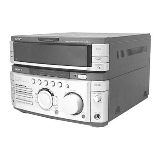
- Page 1 STR-W555 SERVICE MANUAL AEP Model UK Model E Model Australian Model Chinese Model Tourist Model STR-W555 is the tuner and amplifier section in MHC-W555. Photo : E model SPECIFICATIONS FM STEREO/FM-AM RECEIVER MICROFILM – 1 –...
- Page 2 • Keep the temperature of soldering iron around 270˚C WHOSE PART NUMBERS APPEAR AS SHOWN IN THIS during repairing. MANUAL OR IN SUPPLEMENTS PUBLISHED BY SONY. • Do not touch the soldering iron on the same conductor of the circuit board (within 3 times).
-
Page 3: Table Of Contents
TABLE OF CONTENTS 1. GENERAL ................4 2. DISASSEMBLY • Sliding Panel Assembly ............5 3. SERVICE MODE .............. 6 4. ELECTRICAL ADJUSTMENT ........11 5. DIAGRAMS 5-1. Circuit Boards Location ............12 5-2. Block Diagrams • Tuner Section (AEP, UK model) ........13 •... -
Page 4: General
SECTION 1 GENERAL Front Panel 3 4 5 6 7 EXCEPT EA3 (Japan Product), JE EA3 (Japan Product), JE 50 51 52 53 54 55 56 57 58 59 LOCATION OF PARTS AND CONTROLS 1 1/u (Power) button 21 GAME button 43 MIC 2 jack (EA3 (Japan Product), JE 2 SLIDING SENSOR window 22 MUSIC button... -
Page 5: Disassembly
SECTION 2 DISASSEMBLY Note: Follow the disassembly procedure in the numerical order given. • SLIDING PANEL ASSEMBLY 4 Flat type cable (19 core) Slide mechanism 1 Push the OPEN/CLOSE button to open the Sliding panel assembly. 2 Screw (BVTP 3x8) 5 Sliding panel assembly 3 Holder level NOTE FOR INSTALLATION (LEVEL SLIDER) -
Page 6: Service Mode
SECTION 3 SERVICE MODE Connections and Operations When Used Alone Normally, use the unit connected to the HTC-W555 as follows. Basically, when servicing the unit, connect the unit as follows. UNIT HTC-W555 SYSTEM CONTROL 17P AC IN Even when not connected to the HTC-W555, the unit can operate alone as it mounts a power supply (some functions will however not be available). - Page 7 LED and Fluorescent Indicator Tube All Lit, Key Check Mode (Do not connect the HTC-W555.) Procedure: 1. Press 1/u button to turn the set ON. 2. Press the OPEN/CLOSE button to open the sliding panel. 3. Press three buttons DELAY , ENTER/NEXT , and DISPLAY/DEMO simultaneously. 4.
- Page 8 • When operations end abnormally: Display of fluorescent display tube Main Cause Display NO DISC ERR DISC 1 is NO DISC from the beginning FOCUS1 ERR Focus is not imposed properly The focus deviated several times after the disc rotated normally FOCUS2 ERR GFS ERROR GFS ERR...
- Page 9 PANEL Aging Mode This mode is used for opening and closing the sliding panel continuously. Setting the aging mode : With the set at standby condition, press FLASH button, ENTER/NEXT button and STEREO/MONO button together. The aging will start and sliding panel will follow aging sequence as described below. •...
-
Page 10: Electrical Adjustment
SECTION 4 ELECTRICAL ADJUSTMENT TUNER SECTION 0dB=1µV Note 1: As a front-end (FE1) is difficult to repair if faulty, replace it with new one. Note 2: No adjustment is needed for a tuner pack except for AEP, UK, German, East European, CIS models. AM Tuned Level Adjustment (AEP, UK, East European, CIS model only) Note: FM Tuned Level adjustment should be performed after this... - Page 11 FM Polar Adjustment (East European, CIS model only) Procedure : 1. Set the modulation of FM RF SSG to AUDIO 1 kHz, 10 kHz Connection 1 : deviation according to “Connection 1”. 2. Tune the set to 69 MHz. FM RF SSG 3.
-
Page 12: Diagrams
SECTION 5 DIAGRAMS 5-1. CIRCUIT BOARDS LOCATION ENCAPSULATED COMPONENT PRIMARY board (E,EA3,EA4,SP,MY,AR,TW,TH,AUS,CH) SECONDARY board TCB board (AEP,UK.EE,CIS) TUNER board (JE) HEADPHONE board SURR SPK board LOADING PANEL board POWER AMP board MIC / ECHO board MOTOR board FRONT AV board MAIN board PANEL board DETECTOR board... -
Page 13: Block Diagrams
STR-W555 5-2. BLOCK DIAGRAMS – TUNER SECTION – (AEP, UK model) ST +10V FM FRONT END ANTENNA 10.7MHz 10.7MHz 10.7MHz IF AMP IF AMP FM 75Ω OUT L 19 AMP IN L ANT IN IF OUT 1 FM IN MPX IN... -
Page 14: Tuner Section (East European, Cis Model)
STR-W555 – TUNER SECTION – (East European, CIS model) ST +10V FM FRONT END ANTENNA 10.7MHz IF AMP 10.7MHz FM 75Ω OUT R ANT IN IF OUT 1 FM IN 22 MPX IN FM DET OUT Q1-4 COAXIAL OUT L... -
Page 15: Main Section
STR-W555 – MAIN SECTION – VIDEO VOLUME IC111(1/2) IC111(2/2) L-CH R-CH(CD R) SELECT MUTE SWITCH MICON R-CH(PB R) Q183 INTERFACE CN101 MD/V1 POWER SYSTEM IC113(2/2) R-CH MUTE SECTION CONTROL 32 34 30 (Page 19) R-CH(REC R) HTC-W555 DBFB BUFFER L IN... -
Page 16: Power Section
STR-W555 – POWER SECTION – RY781 VIDEO J781 MONITOR R-CH POWER AMP IC901 RY751 TB751 MUTE L-CH FRONT Q181 SPEAKER TA MUTE D751 OVER LOAD Q952 TB201 R-CH REAR D761 SPEAKER MAIN R-CH SECTION OVER LOAD PROTECTOR (Page 17) SWITCH... - Page 17 THIS NOTE IS COMMON FOR PRINTED WIRING BOARDS AND SCHEMATIC DIAGRAMS. (In addition to this, the necessary note is printed in each block.) For schematic diagrams. For printed wiring boards. Note: Note: • All capacitors are in µF unless otherwise noted. pF: µµF •...
-
Page 18: Tuner (Aep, Uk Model) Section
WAVEFORMS – TUNER SECTION – (AEP, UK model) 4.2Vp-p 4.5MHz IC21 @¢ XOUT 2Vp-p 4.332MHz IC1752 !¢ OEC O – TUNER SECTION – (East European, CIS model) 4.2Vp-p 4.5MHz IC21 @¢ XOUT – DISPLAY SECTION – 5.5Vp-p 5MHz IC501 0 X2 5Vp-p 32.768kHz IC501 !£... - Page 19 STR-W555 5-3. SCHEMATIC DIAGRAM – TUNER SECTION – (AEP, UK model) • See page 22 for Waveforms. • See page 52 for IC Block Diagrams. (Page 32) – 23 – – 24 –...
- Page 20 STR-W555 5-4. PRINTED WIRING BOARD – TUNER SECTION – (AEP, UK model) • See page 12 for Circuit Boards Location. • Semiconductor Location Ref. No. Location D1751 IC21 IC41 IC1751 IC1752 (Page 30) – 25 –...
- Page 21 STR-W555 5-5. PRINTED WIRING BOARD – TUNER SECTION – (East European, CIS model) • See page 12 for Circuit Boards Location. • Semiconductor Location Ref. No. Location D1701 D1702 D1703 D1704 IC21 IC41 IC1701 IC1702 Q1701 Q1702 Q1703 (Page 30)
- Page 22 STR-W555 5-6. SCHEMATIC DIAGRAM – TUNER SECTION – (East European, CIS model) • See page 14 for Waveforms. • See page 53 for IC Block Diagrams. (Page 32) – 27 – – 28 –...
-
Page 23: Printed Wiring Board - Main Section
STR-W555 5-7. PRINTED WIRING BOARD – MAIN SECTION – • See page 12 for Circuit Boards Location. (Page 25, 26) (Page 40) (Page 36) (Page 36) (Page 43) • Semiconductor Location Ref. No. Location D101 B-11 D102 B-11 D131 D401... -
Page 24: Schematic Diagram - Main (1/2) Section
STR-W555 5-8. SCHEMATIC DIAGRAM – MAIN (1/2) SECTION – • See page 54 for IC Block Diagrams. (Page 35) (Page 23, 32) (Page 41) (Page 33) (Page 33) (Page 34) (Page 34) – 31 – – 32 –... -
Page 25: Schematic Diagram - Main (2/2) Section
STR-W555 5-9. SCHEMATIC DIAGRAM – MAIN (2/2) SECTION – • See page 29 for Printed Wiring Board. • See page 54 for IC Block Diagrams. (Page 31) (Page 31) (Page 32) (Page 32) (Page 37) (Page 46) (Page 38) (Page 51) -
Page 26: Schematic Diagram - Av/Mic Section
5-10. SCHEMATIC DIAGRAM – AV/MIC SECTION – • See page 54 for IC Block Diagrams. (Page 33) (Page 41) (Page 32) (Page 38) – 35 –... -
Page 27: Printed Wiring Board - Av/Mic Section
STR-W555 5-11. PRINTED WIRING BOARD – AV/MIC SECTION – • See page 12 for Circuit Boards Location. (Page 30) (Page 44) (Page 39) (Page 30) – 36 –... -
Page 28: Schematic Diagram - Power Amp Section
STR-W555 5-12. SCHEMATIC DIAGRAM – POWER AMP SECTION – (Page 34) (Page 34) (Page 34) (Page 35) – 37 – – 38 –... -
Page 29: Printed Wiring Board - Power Amp Section
STR-W555 5-13. PRINTED WIRING BOARD – POWER AMP SECTION – • See page 12 for Circuit Boards Location. (Page 30) (Page 36) (Page 30) (Page 30) – 39 – – 40 –... -
Page 30: Schematic Diagram - Display Section
STR-W555 5-12. SCHEMATIC DIAGRAM – DISPLAY SECTION – • See page 54 for IC Block Diagrams. (Page 35) (Page 46) (Page 32) (Page 45) – 41 – – 42 –... - Page 31 STR-W555 5-15. PRINTED WIRING BOARD – DISPLAY SECTION – • See page 12 for Circuit Boards Location. (Page 29) • Semiconductor Location Ref. No. Location D501 D502 D504 D505 D506 D507 D509 D511 D512 D513 D514 D515 D516 D517 D518...
-
Page 32: Schematic Diagram - Sliding Panel Section
STR-W555 5-16. SCHEMATIC DIAGRAM – SLIDING PANEL SECTION – • See page 54 for IC Block Diagrams. (Page 33) (Page 42) (Page 41) (Page 33) – 45 – – 46 –... -
Page 33: Printed Wiring Board - Sliding Panel Section
STR-W555 5-17. PRINTED WIRING BOARD – SLIDING PANEL SECTION – • See page 12 for Circuit Boards Location. (Page 44) • Semiconductor Location Ref. No. Location (Page 29) (Page 29) D631 D632 D633 D634 D635 D638 D639 D640 D641 D642... -
Page 34: Printed Wiring Board - Trans Section
STR-W555 5-18. PRINTED WIRING BOARD – TRANS SECTION – • See page 12 for Circuit Boards Location. (Page 29) – 49 – – 50 –... -
Page 35: Schematic Diagram - Trans Section
STR-W555 5-19. SCHEMATIC DIAGRAM – TRANS SECTION – (Page 33) – 51 –... -
Page 36: Ic Block Diagrams
5-20. IC BLOCK DIAGRAMS • Tuner section IC21 LC72130 PHASE DETECTOR CHARGE PUMP UNLOCK POWER DETECTOR RESET REFERENCE SWALLOW COUNTER DIVIDER 1/16, 1/17 4BITS 12BITS PROGRAMMABLE DRIVER UNIVERSAL DATA SHIFT REGISTER LATCH COUNTER 3 4 5 6 IC41 LA1838 17 16 DECODER RF. - Page 37 IC1701 IR3R42 19 18 14 13 PHASE COMPARATOR PHASE PHASE COMPARATOR 2 TRIGGER WAVEFORM SEP. REGULATOR SAMPLE GATE & HOLD MUTE BUFFER IC1702 MC14053BCP IC1751 NJM4558D A OUT B.COM B OUT OPEN – A IN– A.COM + – A IN+ B IN–...
- Page 38 • Main (1/2) section IC401 M65850P IC402 MC14053BCP B.COM OPEN A.COM OSCILLATOR LPF2 C.COM 1/2 VCC OPEN CLOCK AUTO MAIN 20KBIT RESET RESET CONTROL SRAM OPEN LPF1 • Main (2/2) section IC851 uPC1237HA IC112 MC14052BCP OVER LOAD DET MUTE 2XCOM OFFSET DET XCOM LATCH/...
- Page 39 • Display section IC505 MC14053BCP B.COM OPEN A.COM C.COM OPEN OPEN IC506 BA3833F RESET 18 RESET RESET REFFERENCE PREF 17 f01 CURRENT LINE 16 f02 LINE 15 f03 BIAS 13 f Bias 12 VCC 11 NC 10 NC • Panel/Motor section IC891 LB1641 T.S.D O.C.P...
-
Page 40: Ic Pin Function
5-21. IC PIN FUNCTION • IC501 SYSTEM CONTROL (uPD780016AYGF-012-3BA) Pin Name Function Pin No. Not used LEVEL A Surround level A signal output LEVEL B Surround level B signal output PROLOGIC RLY Not used DBFB B2 DBFB level 2 signal output DBFB B1 DBFB level 1 signal output TA MUTE... - Page 41 Pin Name Function Pin No. AV IN AV INPUT (VIDEO 2) switch input SENSOR IN Sliding (panel) sensor signal input SIRCS IN Remote sensor signal input SPEANE RST Spectrum analyzer reset output — — Ground — — SOFT Soft test terminal Auto indicator output MOVIE A MOVIE G...
- Page 42 Pin Name Function Pin No. – Ground MOTOR1 Panel motor contol output MOTOR2 PANEL OPEN Panel open switch output PANEL CLOSE Panel close switch output ST.MUTE ST mute signal output STEREO Stereo detection input for tuner TUNED Tuned detection input for tuner Tuner PLL latch output DATA IN Tuner PLL data input...
-
Page 43: Exploded Views
SECTION 6 EXPLODED VIEWS NOTE: The components identified by EA4 : Israel model • Items marked “*” are not stocked since they are mark ! or dotted line with mark : Singapore model. seldom required for routine service. Some delay ! are critical for safety. -
Page 44: Front Panel Section
X-4950-002-1 ESCUTCHEON (ST) ASSY (AEP,UK,EE,CIS) * 61 A-4414-793-A PANEL BOARD, COMPLETE (EA4,TH) 4-977-358-11 CUSHION * 62 4-932-810-11 CUSHION (FL) 4-962-708-11 EMBLEM (4-A), SONY * 63 4-900-849-01 HOLDER (FL) 4-951-620-01 SCREW (2.6X8), +BVTP * 64 1-669-957-11 FRONT AV BOARD * 65... -
Page 45: Slide Mechanism Section
6-3. SLIDE MECHANISM SECTION M891 Ref. No. Part No. Description Remark Ref. No. Part No. Description Remark 4-900-844-01 LEVEL SLIDER 4-900-864-01 BRACKET TOP 4-951-620-01 SCREW (2.6X8), +BVTP 4-900-847-01 GEAR (2) X-4950-394-1 HOLDER (L) ASSY 3-344-059-01 BELT (L) X-4950-395-1 HOLDER (R) ASSY 4-900-845-01 BRACKET SLIDER * 111 1-669-965-11 MOTOR BOARD... -
Page 46: Circuit Boards And Back Panel Section
6-4. CIRCUIT BOARDS AND BACK PANEL SECTION (AEP,EE,CIS,EA3,EA4,SP,MY,TW) (EA3,SP,MY,TW) (AR) (AUS) (E,TH,CH,JE) not supplied (UK) (E,JE) T901 M901 not supplied The components identified by mark ! or dotted line with mark ! are critical for safety. Replace only with part number specified. Ref. -
Page 47: Electrical Parts List
DETECTOR FRONT AV SECTION 7 ELECTRICAL PARTS LIST HEADPHONE LOADING PANEL Note: • Due to standardization, replacements in the parts list • CAPACITORS The components identified by may be different from the parts specified in the uF : µ F mark ! or dotted line with mark diagrams or the components used on the set. - Page 48 LOADING PANEL MAIN Ref. No. Part No. Description Remark Ref. No. Part No. Description Remark D639 8-719-046-44 DIODE SEL5221S (DSP DELAY) < SWITCH > D640 8-719-046-44 DIODE SEL5221S (DSP REVERB) D641 8-719-046-44 DIODE SEL5221S () +) S631 1-762-378-11 SWITCH, TACTILE (0 –) D642 8-719-058-04 DIODE SEL5223S-TP15 (MULTI JOG STATION) S632...
- Page 49 MAIN Ref. No. Part No. Description Remark Ref. No. Part No. Description Remark C121 1-126-964-11 ELECT 10uF C418 1-126-964-11 ELECT 10uF C122 1-162-291-31 CERAMIC 560PF C731 1-104-664-11 ELECT 47uF C123 1-136-165-00 FILM 0.1uF C732 1-126-964-11 ELECT 10uF C124 1-136-165-00 FILM 0.1uF C751 1-136-495-11 FILM...
- Page 50 MAIN Ref. No. Part No. Description Remark Ref. No. Part No. Description Remark D805 8-719-024-99 DIODE 11ES2-NTA2B R105 1-249-441-11 CARBON 100K 1/4W D806 8-719-024-99 DIODE 11ES2-NTA2B R106 1-249-417-11 CARBON 1/4W F D807 8-719-024-99 DIODE 11ES2-NTA2B R108 1-249-417-11 CARBON 1/4W F D808 8-719-024-99 DIODE 11ES2-NTA2B R109...
- Page 51 MAIN MIC/ECHO Ref. No. Part No. Description Remark Ref. No. Part No. Description Remark R194 1-249-417-11 CARBON 1/4W F R761 1-249-432-11 CARBON 1/4W R195 1-249-417-11 CARBON 1/4W F R762 1-249-437-11 CARBON 1/4W R196 1-249-429-11 CARBON 1/4W R763 1-249-397-11 CARBON 1/4W F R340 1-247-843-11 CARBON 3.3K...
- Page 52 MIC/ECHO MOTOR Ref. No. Part No. Description Remark Ref. No. Part No. Description Remark C6016 1-126-967-11 ELECT 47uF R6004 1-249-417-11 CARBON 1/4W F (EA3(Japan Product),JE) (EA3(Japan Product),JE) R6005 1-249-441-11 CARBON 100K 1/4W C6017 1-164-159-11 CERAMIC 0.1uF (EA3(Japan Product),JE) R6006 1-249-417-11 CARBON 1/4W F C6018 1-126-967-11 ELECT...
- Page 53 PANEL Ref. No. Part No. Description Remark Ref. No. Part No. Description Remark A-4414-196-A PANEL BOARD, COMPLETE (AEP,UK) C615 1-162-288-31 CERAMIC 330PF C616 1-162-288-31 CERAMIC 330PF ********************* C617 1-162-288-31 CERAMIC 330PF A-4414-212-A PANEL BOARD, COMPLETE C618 1-162-288-31 CERAMIC 330PF ********************* (EA3(Malaysia Product),SP,MY,TW,CH) C619 1-162-288-31 CERAMIC...
- Page 54 PANEL Ref. No. Part No. Description Remark Ref. No. Part No. Description Remark Q503 8-729-422-57 TRANSISTOR UN4111 R547 1-247-881-00 CARBON 120K 1/4W Q504 8-729-422-57 TRANSISTOR UN4111 R548 1-249-433-11 CARBON 1/4W Q505 8-729-422-57 TRANSISTOR UN4111 R549 1-249-429-11 CARBON 1/4W R550 1-249-409-11 CARBON 1/4W F Q506 8-729-422-57 TRANSISTOR UN4111...
- Page 55 PANEL POWER AMP Ref. No. Part No. Description Remark Ref. No. Part No. Description Remark R605 1-249-403-11 CARBON 1/4W F A-4414-195-A POWER AMP BOARD, COMPLETE (AEP,UK) ************************* R606 1-249-403-11 CARBON 1/4W F R607 1-249-415-11 CARBON 1/4W F A-4414-209-A POWER AMP BOARD, COMPLETE R608 1-247-807-31 CARBON 1/4W...
- Page 56 POWER AMP PRIMARY SECONDARY SURR SPK Ref. No. Part No. Description Remark Ref. No. Part No. Description Remark < RESISTOR > 1-669-953-11 PRIMARY BOARD ************* R133 1-249-425-11 CARBON 4.7K 1/4W F R183 1-249-425-11 CARBON 4.7K 1/4W F < CONNECTOR > R901 1-249-417-11 CARBON 1/4W F...
- Page 57 SURR SPK Ref. No. Part No. Description Remark Ref. No. Part No. Description Remark < GROUND > 1-163-031-11 CERAMIC CHIP 0.01uF 1-163-038-91 CERAMIC CHIP 0.1uF * E781 4-870-539-11 PLATE, GROUND 1-163-031-91 CERAMIC CHIP 0.01uF < JACK > 1-163-038-91 CERAMIC CHIP 0.1uF 1-163-077-00 CERAMIC CHIP 0.1uF...
- Page 58 Ref. No. Part No. Description Remark Ref. No. Part No. Description Remark 1-567-389-11 FILTER, CERAMIC < FILTER > < CONNECTOR > LPF41 1-239-845-11 FILTER, LOW PASS LPF42 1-239-845-11 FILTER, LOW PASS 1-774-292-21 HOUSING, CONNECTOR (PC BOARD) 15P < TRANSISTOR > <...
- Page 59 Ref. No. Part No. Description Remark Ref. No. Part No. Description Remark 1-216-037-00 METAL CHIP 1/10W A-4303-597-A TCB BOARD, COMPLETE (AEP,UK) 1-216-001-00 METAL CHIP 1/10W ******************* 1-247-843-11 CARBON 3.3K 1/4W F < CAPACITOR > 1-216-065-91 METAL CHIP 4.7K 1/10W 1-216-097-91 METAL CHIP 100K 1/10W 1-163-141-00 CERAMIC CHIP...
- Page 60 Ref. No. Part No. Description Remark Ref. No. Part No. Description Remark 1-126-967-11 ELECT 47uF JR51 1-216-295-11 METAL CHIP 1/10W 1-162-306-11 CERAMIC 0.01uF JR52 1-216-295-11 METAL CHIP 1/10W 1-126-967-11 ELECT 47uF JR53 1-216-296-11 METAL CHIP 1/8W 1-163-031-11 CERAMIC 0.01uF JR54 1-216-295-11 METAL CHIP 1/10W 1-163-031-11 CERAMIC...
- Page 61 Ref. No. Part No. Description Remark Ref. No. Part No. Description Remark 1-216-214-00 METAL CHIP 4.7K 1/8W MISCELLANEOUS ************* 1-216-025-91 METAL CHIP 1/10W 1-216-073-00 METAL CHIP 1/10W 1-773-125-11 WIRE (FLAT TYPE) (19 CORE) 1-216-089-91 METAL CHIP 1/10W 1-233-545-31 ENCAPSULATED COMPONENT 1-249-429-11 CARBON 1/4W (E,EA4,AR,TH,AUS)
- Page 62 STR-W555 98F0972-1 Sony Corporation Printed in Japan © 1998. 6 9-922-908-11 Home A&V Products Company Published by Quality Assurance Dept. – 78 – (Shibaura)
Need help?
Do you have a question about the STR-W555 and is the answer not in the manual?
Questions and answers