
Related Manuals for Freefly ALTA 8


Summary of Contents for Freefly ALTA 8
- Page 1 AIRCRAFT FLIGHT MANUAL 770- 000 48 | R E V I S I O N A | 0 3.23. 2016...
-
Page 2: Revision History
REVISION HISTORY REVISION DATE DESCRIPTION March 2016 Initial Release A LTA 8 A I R C R A F T F L I G H T M A N U A L PA R T N U M B E R : 77 0- 000 48... -
Page 3: Table Of Contents
Propellers First Person View (FPV) Tuning ALTA 8 ALTA 8 Flight Parameters Resetting ALTA 8 WiFi Password OPERATING ALTA 8 Flight Controller Modes Home Switch | A I R C R A F T F L I G H T M A N U A L... - Page 4 Loss of Radio Control Signal Loss of FPV Signal PERFORMANCE Weight / Endurance Performance Data Allowable Gross Weight Gross Weight MAINTAINING ALTA 8 General Information and Techniques Maintenance Items Firmware Update Process Motor Alignment Guidelines Following an Accident | A I R C R A F T F L I G H T M A N U A L...
- Page 5 TROUBLESHOOTING APPENDIX Appendix A. Default Tuning Values Appendix B. Data Logging Fields | A I R C R A F T F L I G H T M A N U A L...
-
Page 6: Alta 8 Overview
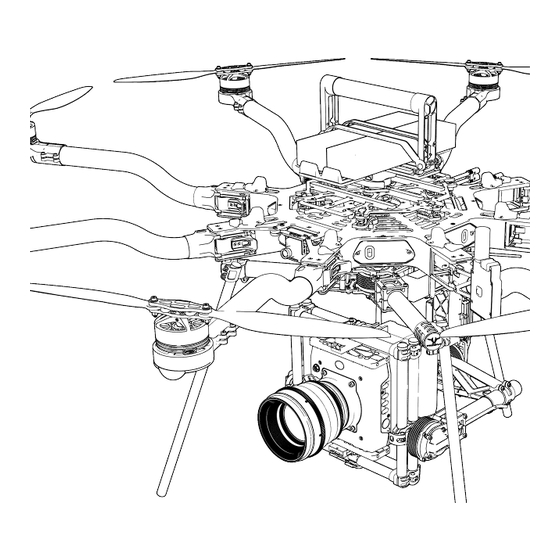
ALTA 8 OVERVIEW | A I R C R A F T F L I G H T M A N U A L... -
Page 7: Disclaimer And Warning
You agree that you are solely responsible for your conduct while using ALTA 8, and for any direct or indirect consequences that may result from its use. You agree to only use ALTA 8 for proper purposes that are in accordance with local and airspace rules and regulations. - Page 8 » It is your responsibility to perform a full system check of ALTA 8 prior to every flight. » It is your responsibility to learn how to safely operate ALTA 8 and to adhere to all applicable rules and regulations.
-
Page 9: Limitation Of Liability
» Use of ALTA 8 in a physically or mentally impaired capacity. » Use of ALTA 8 without sufficient training. » Use of ALTA 8 in unsafe conditions, including but not limited to, bad or severe weather, such as rain, wind, snow, lightning, dust storms, etc., or in areas of magnetic or radio interference, such as power stations, broadcasting and cell phone towers, government prohibited airspace, etc. - Page 10 » Infringement of third party data, audio or video rights recorded when using ALTA 8. | A I R C R A F T F L I G H T M A N U A L...
-
Page 11: Introduction
ALTA 8 is a professional multi-rotor aircraft designed for demanding cinematic, television, and photographic applications. Within five minutes, ALTA 8 can unfold from its carrying case to flying some of the most capable cinema cameras on either the top or bottom of the aircraft. -
Page 12: Symbols, Abbreviations And Terminology
SYMBOLS, ABBREVIATIONS AND TERMINOLOGY WARNINGS, CAUTIONS AND NOTES Throughout the manual, warnings, cautions and notes are used to highlight various important procedures. These are defined as follows: WARNING CAUTION NOTE Warnings are used to highlight proce- Cautions are used to highlight proce- Notes are used to highlight specific dures which, if not strictly observed, dures which, if not strictly observed,... - Page 13 Pressure Altitude Altitude measured from standard sea level pressure (1013.2 mbar, 29.92 in. Hg) by a pressure or barometric altimeter It is the indicated pressure altitude corrected for position and instrument error. In this Manual, altimeter instrument errors are assumed to be zero POWER TERMINOLOGY Maximum Continuous The maximum typical power output of a...
- Page 14 WEIGHT AND BALANCE Maximum Takeoff Maximum allowable weight at liftoff Weight (MTOW) Standard Empty Weight Weight of a standard aircraft Basic Empty Weight Standard empty weight plus optional equipment Useful Load Difference between take off weight and basic empty weight Payload Useful load less battery weight GENERAL TERMINOLOGY...
-
Page 15: Dimensions
DIMENSIONS (18.0) (8.6) 1325 (52.1) (18.0) U N FO L D E D P L A N V I E W W I T H B O O M N U M B E R I N G S C H E M E M M ( I N C H ) (8.6) (14.1) - Page 16 (25.9) (24.2) (9.8) FO L D E D S I D E V I E W M M ( I N C H ) (24.2) (10.2) (25.9) (9.8) FO L D E D P L A N V I E W M M ( I N C H ) (10.2) (24.2)
-
Page 17: Included Items
INCLUDED ITEMS 1. Case 10. FP V Cables 2. ALTA 8 a. Skyzone/BOSCAM 3. Case Lid Foam b. BOSCAM, small connector 4. Isolator Cartridges c. ImmersionRC/Fat Shark a. (6) Teal (Installed) d. Ready Made RC b. (6) Black 11. (2) M3 × 6 Flat Head for Accessory Mount c. -
Page 18: Specifications
Motor Max Instantaneous 950 W Peak Power Output Maximum RPM (flat rated) 6300 RPM Equivalent Kv Electronic Speed Controller Freefly Silent-Drive Sine Wave ESC PROPELLERS Make and Model Freefly ALTA Propeller Material Carbon fiber with balsa core Propeller Orientation (4) CW and (4) CCW Props Propeller Type 18 ×... - Page 19 WEIGHTS Maximum Gross for Takeoff 18.1 kg (40.0 lbs) Maximum Useful Load 12.0 kg (26.4 lbs) Maximum Payload 9.1 kg (20.0 lbs) Typical Standard Empty Weight: 6.2 kg (13.6 lbs) WA R N I N G Always refer to the following aircraft limitations section for complete information on allowable maximum gross weights at different altitudes and temperatures before any flight.
- Page 20 FLIGHT CONTROLLER Model Name Freefly SYNAPSE flight controller Flight Modes Manual, Height Mode, Position Mode, Return-To-Home, Autoland Supported Inputs: DSMX, DSM2, S.Bus, S.Bus2, PPM, FPV SD Supported Radios Futaba S.Bus & S.Bus2, DSMX, DSM2 (Spektrum/JR), PPM, PPM Invert, PPM Graupner...
- Page 21 PAYLOAD MOUNTING Mounting Locations Bottom and Top Mount Mounting System Freefly Toad In The Hole (TITH) Quick Release FPV Camera Mount Between Booms 8 & 1 FPV Transmitter Mount Boom 2 | A I R C R A F T F L I G H T M A N U A L...
-
Page 22: Limitations
6300 RPM Maximum Battery Voltage 25.2 Volts Minimum Average Battery Voltage 19.2 Volts ENVIRONMENTAL LIMITATIONS Do not fly ALTA 8 in temperatures exceeding 45ºC (113ºF) or below -20ºC(-4ºF). FLIGHT CONTROLLER LIMITS Maximum Pitch/Roll Angle 45° Maximum Yaw Rate 150° / second Must additionally observe battery temperature ratings. - Page 23 WEIGHT LIMITS Maximum Payload 9.1 kg (20.0 lbs) Maximum Takeoff Weight See following table | A I R C R A F T F L I G H T M A N U A L...
-
Page 24: System Diagrams
SYSTEM DIAGRAMS sUAS OVERVIEW GPS Satellite HD Video Link, ALTA App Preview Monitor* FPV Rx, Preview Monitor* Radio Controller* *NOT INCLUDED 2.4GHz MōVI Controller* | A I R C R A F T F L I G H T M A N U A L... - Page 25 FLIGHT CONTROL A. Spektrum Receiver SYNAPSE Flight DSMX, DSM 2 Controller B. Futaba Receiver or Generic Receiver S.BUS, S.BUS 2 or PPM Status Light 8 Position Lights | A I R C R A F T F L I G H T M A N U A L...
- Page 26 POWER SYSTEM Motor Motor Lights Lights SYNAPSE Flight Motor Motor Controller Lights Lights F U S E Motor F U S E Motor Lights Lights R E G U L A T O R S EC5 Connector Motor Motor Lights Lights Flight Flight...
- Page 27 FPV EQUIPMENT F P V Camera (not included) F P V Camera Cable FPV Tx (not included) FPV Tx Cable Boscam/Skyzone or Fat Shark/ImmersionRC FPV Camera Lead Pre-installed SYNAPSE Flight FPV Tx Lead Controller Pre-installed | A I R C R A F T F L I G H T M A N U A L...
-
Page 28: Alta Mobile App
ALTA 8 can accommodate a variety of Lithium Polymer (LiPo) flight battery packs. Battery packs must be 6S, having a nominal voltage of 22.2 V. Only run ALTA 8 using two packs at a time. Each pack must have a continuous discharge rating of 250 amps or greater, and a peak discharge rating of 500 amps or greater. -
Page 29: Setting Up Alta 8
SETTING UP ALTA 8 | A I R C R A F T F L I G H T M A N U A L... - Page 30 UNFOLDING ALTA 8 ALTA 8 features swan-neck booms that fold into a compact size for travel. They are secured in an open position for flight using over- center latches. TO UNFOLD ALTA 8 Remove ALTA 8 from case Fold down all eight boom retention clips...
- Page 31 Snap shut all eight boom latches until they “click” Visually confirm all latches are seated properly Remove prop protectors | A I R C R A F T F L I G H T M A N U A L...
- Page 32 TO FOLD ALTA 8 Secure props with prop protectors Unlatch all eight booms Close ALTA 8 booms Fold up all eight boom retention clips to secure booms | A I R C R A F T F L I G H T M A N U A L...
-
Page 33: Radio Installation
RADIO INSTALLATION RADIO CONTROLLER RECEIVER ALTA 8 requires the installation of a radio control system. S.Bus, S.Bus2, DSM2, DSMX, and PPM (including inverted PPM and Graupner) receiver types are supported. Additionally, ALTA 8 supports radio receiver diversity using S.Bus, S.Bus2, DSM2 and DSMX receivers. - Page 34 Plug signal wire into receiver If using telemetry, plug in telemetry wire (refer to the Voltage Temeletry section) Feed receiver antenna into lower antenna tube Secure receiver using the provided double sided tape to inside of receiver housing Reattach closeout panel | A I R C R A F T F L I G H T M A N U A L...
- Page 35 Route antenna wires into the two antenna tubes below ALTA 8 chassis Repeat steps 1-8 for dual receivers (only applies to Futaba receivers) FOR SPEKTRUM/JR: Locate the noted closeout panels used for Spektrum/JR receiver installation (between booms 3 & 4 and 7 & 8) Remove side closeout panel using a 2.0mm hex driver...
- Page 36 Reattach closeout panel Plug in receiver/satellite into signal cable Attach receiver/satellite to exterior using double sided tape Repeat steps 1-6 for dual receivers | A I R C R A F T F L I G H T M A N U A L...
- Page 37 ALTA 8 supports battery voltage telemetry on Futaba radios using a receiver that supports an external voltage sensor, such as the R7008SB. Installing the telemetry wire is easiest when initially installing the receiver. To set up ALTA 8 with voltage telemetry for Futaba radios: Remove the closeout panel between booms 2 and 3 with a 2.0mm...
-
Page 38: Radio Mapping
RADIO MAPPING ALTA 8 can be used with a variety of radio controllers. Different radio controllers can map functions to different channels, so properly mapping controller channels to ALTA 8 functions is an important step before flying. Radio mapping is performed using the ALTA App. - Page 39 Always ensure the Configuration Jumper is removed prior to adjusting radio settings to prevent unintentional motor starts. Power ALTA 8 using a battery pack or by plugging in the included USB-Futaba cable into an available port on a Futaba receiver Open the ALTA App and connect to ALTA 8 Open Configurations >...
- Page 40 ONCE CHANNELS ARE MAPPED Remove the battery or USB-Futaba cable from ALTA 8 Replace the Configuration Jumper FUNCTION DESCRIPTIONS The following functions can be mapped to radio controller channels. These are found in the Radio section of the Configurations menu in the ALTA App. Each function is also represented by a chart that responds to control input allowing for quick verification of mapping settings.
- Page 41 DISARM SAFETY The Disarm Safety Switch aids in preventing accidental motor disarming while the ALTA is in flight and in manual mode. It may be mapped to either a two-position or three-position switch. To set up the Lockout Switch, refer to the Mapping Channels section or the ALTA Aircraft Flight Manual.
- Page 42 The following are channel mapping configurations as set in the ALTA App. These are recommendations only. Depending on exact radio models, these may help as an initial configuration. However, it is up to the pilot setting up ALTA 8 for flight to determine if these settings are appropriate.
-
Page 43: Configuring For Mōvis
CONFIGURING FOR MōVI A MōVI can be attached to either the top or bottom of ALTA 8 via the Freefly Toad In The Hole (TITH) quick release. ALTA 8 comes pre-configured for GroundView mounting a MōVI. GROUNDVIEW Prepare your MōVI for both GroundView and SKyView flight (see MōVI manual) Attach landing gear Install TITH receiver on MōVI... - Page 44 Connect and secure the supplied inverted landing gear to the bottom Toad Remove Battery Mount Quick Release Connect MōVI to top Toad | A I R C R A F T F L I G H T M A N U A L...
-
Page 45: Isolator Cartridges
Different Isolator Cartridges can be used to fine tune vibration damping performance for different payload weights. Three isolation cartridge styles are provided with ALTA 8. The cartridges have o-rings colored red for light payloads, teal for medium payloads, and black for heavy payloads. Flight testing may be required to determine the optimal isolator for a given setup. -
Page 46: Battery Installation
BATTERY INSTALLATION Batteries may be installed on either the top or bottom of an ALTA 8 and are always mounted opposite of the payload location. In both locations, battery packs are secured with silicone straps tensioned across the packs. The straps are secured using studs located on either side of the packs. - Page 47 GROUNDVIEW Place battery retention strap studs at the appropriate height for battery packs Adjust battery stops to fit battery packs Attach the single-hole end of the battery retention straps to the studs | A I R C R A F T F L I G H T M A N U A L...
- Page 48 Place battery packs on battery tray CA U T I O N Do not install batteries on a tray with the Toad In The Hole adapter installed. If installing batteries without the Battery Mount Quick Release for GroundView, remove the Toad adapter first. Tension and secure battery retention straps | A I R C R A F T F L I G H T M A N U A L...
- Page 49 SKYVIEW CA U T I O N Always completely secure the inverted landing gear by closing the TITH quick release lever. Inverted landing gear that are not completely attached can rotate and unplug battery leads. Pinch the battery tray handles and slide to remove it from landing gear Attach the single-hole ends of the battery retention straps to the studs on the battery tray Place battery packs onto battery tray...
- Page 50 Tension and secure battery retention straps Slide tray with battery packs back into landing gear Ensure tray and battery packs are secure | A I R C R A F T F L I G H T M A N U A L...
-
Page 51: Compass Calibration
WA R N I N G Verify ALTA 8 is disarmed prior to performing a compass calibration. To ensure ALTA 8 does not arm, remove the Configuration Jumper, set the mode switch to Height or Position, or set the home switch to Set New Home Position. - Page 52 TO PERFORM A COMPASS CALIBRATION: Secure a battery onto ALTA 8 Plug in the battery Open the ALTA App Select Configurations > More > Compass RO L L+3 60º Under Calibration, select Start Manual YAW +90 º R O LL + 1 8 0 º...
- Page 53 AUTOMATIC COMPASS CALIBRATION Automatic Compass Calibration will use compass readings over time to resolve an accurate compass calibration. Manual calibration is recommended when moving to a new location and an accurate compass calibration is needed immediately for using Position Mode. In the ALTA App, select Configurations >...
-
Page 54: Propellers
The propellers installed on booms 1, 3, 5, and 7 spin clockwise when viewed from above ALTA 8, and the propellers installed on booms 2, 4, 6, and 8 spin counterclockwise when viewed from above. - Page 55 CHECKING PROP BOLT TIGHTNESS Over time, the bolts that hold the propeller blades to the prop hub can loosen due to vibration. To check prop bolt tightness, twist the prop about its length. If there is free play, the prop bolt is too loose. Use the provided 2.5mm hex driver and wrench to tighten the bolt and nut that secure the prop blade just enough to remove the play.
-
Page 56: First Person View (Fpv)
FIRST PERSON VIEW (FPV) ALTA 8 and SYNAPSE can power a variety of first person view (FPV) cameras and transmitters, as well as add informational on-screen display (OSD) elements to aid in FPV flying. Each supplied cable has the one side with a connector that mates with a cable located in the closeout panel between booms 1 &... - Page 57 Locate the FPV camera cable included in the ALTA 8 package Pass the FPV cable through the closeout panel grommet and connect to the mating FPV camera lead inside ALTA 8. Connect the other end directly to the camera Replace front closeout panel.
- Page 58 Mount FPV camera on the FPV mount on the front ALTA 8 using the provided hardware TRANSMITTER Mount FPV transmitter on the provided carbon fiber accessory mount plate Attach accessory mount to boom 2 with M3x6 flathead bolts Locate the appropriate FPV transmitter cable. The following cables are included:...
- Page 59 Remove the side closeout panel with the FPV transmitter lead using the 2.0mm hex driver Pass transmitter cable through the underside of the hinge, and connect to the FPV transmitter lead Replace side closeout panel Zip tie the FPV transmitter lead to the boom cable bundle for strain relief | A I R C R A F T F L I G H T M A N U A L...
- Page 60 N A M E D E S C R I P T I O N Displays the height of ALTA 8 from its Height starting point in meters or feet...
- Page 61 Turns off all artificial horizon components Adds a horizon line that moves up and down as Artificial Basic ALTA 8 changes pitch, and rolls as ALTA 8 rolls Horizon Adds pitch marks at intervals defined Ladder by the Pitch Interval setting...
- Page 62 Displays a bar on the bottom of the screen that scales with the side-to-side velocity component Sideslip The bar will extend left to indicate leftward velocity, or right to indicate rightward velocity | A I R C R A F T F L I G H T M A N U A L...
-
Page 63: Tuning Alta 8
ALTA 8 comes pre-tuned for a wide variety of payloads and flying conditions. Generally, additional tuning is not required to fly ALTA 8, and additional tuning will only need to take place if more customization of control feel is desired. Default tuning values are included in Appendix A, Default Tuning Values. - Page 64 Stiffness is adjusted for pitch and roll simultaneously, and yaw independently. It changes how stable ALTA 8 is in these axes and is the primary variable to adjust when tuning. When tuning Stiffness first, or making large stiffness changes, Hold Strength should be set to a low, non-zero value.
- Page 65 Hold Strength Gain tunes how much ALTA 8 will attempt to stay on a desired altitude in Height Hold mode only. A higher value will result in height being held more precisely. Too high of a value can cause ALTA 8 to overreact to winds, gusts or turbulent air.
-
Page 66: Alta 8 Flight Parameters
MAXIMUM PITCH/ROLL ANGLE This sets the maximum angle ALTA 8 will be allowed to fly in all modes and in all flight conditions. MAXIMUM YAW RATE This is the maximum rate ALTA 8 will yaw (pan) when at full stick deflection. - Page 67 ALTA 8 is flying. MAXIMUM CEILING This adjusts the highest altitude the ALTA 8 is allowed to climb from its starting point while in Height or Position modes. If the maximum ceiling is exceeded in Manual mode, the Status Light will illuminate white.
- Page 68 RANGE Range sets the maximum distance ALTA 8 may fly away from the home point while in Position mode. If the range is exceeded in Manual mode, the status light will illuminate white. | A I R C R A F T F L I G H T M A N U A L...
-
Page 69: Resetting Alta 8 Wifi Password
RESETTING ALTA 8 WIFI PASSWORD TO RESET THE WIFI PASSWORD: Simultaneously: Press and hold the square reset button on the GPS unit Power on ALTA 8 Hold the reset button for 10 seconds Power cycle ALTA 8 Once complete, the WiFi password will be removed. A new one can then be set in the ALTA App. -
Page 70: Operating Alta 8
OPERATING ALTA 8 | A I R C R A F T F L I G H T M A N U A L... -
Page 71: Flight Controller Modes
When the throttle stick is centered, ALTA 8 will enter Height Hold. In Height Hold, ALTA 8 will maintain a target altitude and try to correct for drift. If a disturbance moves ALTA 8 away from this target altitude, ALTA 8 will climb or descend to return to the target altitude. - Page 72 During an LOS event, ALTA 8 will first check its current altitude against Safe Height. If it is lower, it will climb to Safe Height, and if ALTA 8 is above Safe Height, it will remain at its current altitude. Next, ALTA 8 will fly back to the home position at the RTH Speed set in the ALTA 8 App.
- Page 73 The Autoland function will command ALTA 8 to hover for 10 seconds and will then land in place. If ALTA 8 is above the app-configurable Safe Height setting, ALTA 8 will first descend to it at the Maximum Descent Rate. After reaching this height, ALTA 8’s descent will slow to the Autoland Descent Rate.
-
Page 74: Home Switch
The home switch has three settings, Set Home, RTH Off and RTH On. SET HOME Set Home sets a new home point at ALTA 8’s current position. This could be useful for setting a point away from the initialization point, such as if the ALTA 8 was started underneath an overhang or a tree. -
Page 75: Disarm Safety Switch
DISARM SAFETY SWITCH The Disarm Safety Switch aids in preventing accidental motor disarming while the ALTA 8 is in flight and in manual mode. It may be mapped to a two or three-position switch. To set up the Disarm Safety Switch, refer to the Radio Mapping section of this manual. 3 P O S I T I O N S W I TC H F U N CT I O N On - Disarming is not possible. -
Page 76: Status Light
STATUS LIGHT The rear-facing Status Light shows the status of ALTA 8 as it boots, arms and flies. The following table shows the different meanings of the light in the various flight phases. F L I G H T P H A S E... - Page 77 Nominal flight status Height hold inactive Flight - Height Slow Flashing Height hold active Hold White Solid or Flight critical alarm - Land Flashing Red immediately! Nominal flight status Height hold inactive Position hold inactive Slow Flashing Flight - Position Height Hold or Position Hold Active White Hold...
-
Page 78: Alarms
ALTA 8 will notify the pilot of critical alarms using the Status Light. These alarms indicate a serious issue has been observed in the behavior of the ALTA 8 that, if not acted upon immediately, can cause loss of control. Never continue a flight when ALTA 8 indicates an alarm. -
Page 79: Orientation Lights
ORIENTATION LIGHTS BOTTOM VIEW The boom-end mounted Orientation Lights indicate both the orientation of ALTA 8 in flight and the status of the individual motor Electronic Speed Controllers (ESCs) during other operational phases. The following table shows the different meanings of the light colors in the various operational phases. -
Page 80: Alta App Monitor
If Bad, the compass may require recalibration (see the Compass Calibration section in this manual). Station displays if ALTA 8 is currently over its commanded position over the ground, or if it attempting to fly to it. -
Page 81: Data Logging
DATA LOGGING ALTA 8 automatically logs flight and control data when ALTA 8 is armed for flight. Data is recorded as a .csv file at a rate of 25 Hz on a microSD card installed on the top of the GPS/Compass module. A table of recorded data is included in Appendix B. -
Page 82: Normal Procedures
NORMAL PROCEDURES... -
Page 83: Unpacking And Setup
CONFIGURE as necessary AMPLIFICATION To set up ALTA 8 for flight, remove it from the case and remove the prop protectors. Stow the six boom retention clips by folding them down. The clips only fold in one direction and are spring-loaded to stay in open and closed detented positions. -
Page 84: Before Starting
BEFORE STARTING Payload SECURED Isolator Cartridges VERIFY SECURE microSD Card INSTALLED Props CHECK CONDITION, VERIFY TIGHT Prop Hubs VERIFY SECURE Motors CHECK CONDITION Radio Controller ON, VERIFY TX BATT Radio Controller Model SELECT Aircraft Placement AWAY from people and obstacles Battery Pack Voltage VERIFY ABOVE 24V Battery Packs... - Page 85 While the SYNAPSE flight controller initializes, keep the ALTA 8 as stable as possible. Wedging a foam prop protector between the stationary gimbal or landing gear and the ALTA 8 frame can be used to stabilize ALTA 8 from spinning during this process.
-
Page 86: Before Takeoff
ALTA 8’s motors. ALTA 8 can only be armed for flight when it is in the Manual Mode, and the Home Switch is in the middle position. To arm, hold full low throttle and full left yaw. - Page 87 ALTA 8 should pitch, roll and yaw slightly due to isolator cartridge flex. Ensure that the ALTA 8 behaves as expected. If it does not, shutdown ALTA 8 and ensure the props are installed in the correct orientation.
-
Page 88: After Every Flight
Disarm Safety to off to allow the motors to stop. Once the motors are stopped and disarmed, the Orientations Lights will flash green and the Status Light will slowly flash white, indicating it is safe to approach ALTA 8. WA R N I N G Only approach ALTA 8 after confirming that it is disarmed by verifying the Status Light and Orientation Light colors. - Page 89 the props or motors and cause damage. After the flight, ensure there is no damage to the props and that the motors still spin freely and quietly. Take extra care when operating in areas with large amounts of debris, such as in sand, dirt, or gravel. After flight is also a good time to check a battery pack’s condition.
-
Page 90: After Last Flight
Packing ALTA 8 is similar to the unpacking process. Keeping ALTA 8 on the payload or landing gear facilitates the process as ALTA 8 may be turned on the Toad In The Hole adapter while folding the props and booms. Make sure that the handle is aligned front-to-back when putting ALTA 8 in the included case, and that the battery leads are facing to the right. -
Page 91: Emergency Procedures
EMERGENCY PROCEDURES... -
Page 92: Emergency Guidance
EMERGENCY GUIDANCE The emergency procedures listed in this section are the recommended practices for handling the aircraft in the event of an aircraft emergency. This guidance should be considered and applied as necessary. The risk of an emergency occurring can be reduced substantially through proper aircraft maintenance, by performing thorough inspections before and after all flights, and with careful pre-flight planning. -
Page 93: Status Light Warning Indicator Illuminates
They are indicated by the Status Light turning red. It is always recommended to land as soon as possible when the Status Light indicates a warning and investigate the problem while ALTA 8 is on the ground. -
Page 94: Pilot Disorientation
If a good GPS signal is available, enable Position Mode so ALTA 8 will stay in one place. Use yaw only to reorient ALTA 8 so the nose is pointed away, then use the roll control to verify the orientation of ALTA 8. -
Page 95: Unexpected Flight Controller Behavior
LAND as soon as possible AMPLIFICATION If the ALTA 8 behaves unexpectedly, neutralize control inputs and observe ALTA 8. If it is still flying in an uncommanded manner, switch to Manual mode if it is in Height or Position modes. In most cases, unexpected behavior is due to erroneous sensor readings, or degraded GPS signal reception. -
Page 96: Battery Exhaustion
During the time ALTA 8 is descending, use pitch and roll to avoid people or objects during the descent and landing. ALTA 8 will not Autoland if it is in Manual Mode. Full throttle authority is available to the pilot in a battery exhaustion event. -
Page 97: Loss Of Radio Control Signal
Loss of Signal (LOS) can occur if the radio controller stops transmitting a signal, or if ALTA 8 is too far away to receive it. In the event ALTA 8 detects a LOS, it will automatically execute a Return-to-Home or Autoland as configured in the App. -
Page 98: Loss Of Fpv Signal
LOSS OF FPV SIGNAL Control Inputs AS REQUIRED Visual Contact ESTABLISH ALTA 8 POSITION for optimal signal reception If visual contact or FPV signal is not reestablished Mode Switch POSITION Home Switch RETURN TO HOME Throttle AS REQUIRED AMPLIFICATION An FPV Loss of Signal (LOS) can occur if the aircraft flies out of range, or if it flies behind an object that interrupts the signal line of sight. -
Page 99: Performance
PERFORMANCE | A I R C R A F T F L I G H T M A N U A L... -
Page 100: Weight / Endurance Performance Data
PERFORMANCE WEIGHT / ENDURANCE PERFORMANCE DATA Conditions: Altitude Sea Level, ISA Winds Zero | A I R C R A F T F L I G H T M A N U A L... - Page 101 ALLOWABLE GROSS WEIGHT | A I R C R A F T F L I G H T M A N U A L...
-
Page 102: Maintaining Alta 8
MAINTAINING ALTA 8 | A I R C R A F T F L I G H T M A N U A L... -
Page 103: General Information And Techniques
222) is used on structural fasteners. BOLT INSTALLATION The Freefly hex drivers included with ALTA 8 are designed to help limit the torque that can be applied to each bolt. Thread all fasteners into their respective holes until “snug”. This is when the... -
Page 104: Maintenance Items
Propeller blades should be removed when making a change to the configuration of the ALTA 8 to prevent propeller strikes in the event of unintentional motor starts and should be replaced on an as needed basis if they become damaged. Generally, a nick on the leading edge that is large enough to catch a fingernail indicates that the prop should be replaced. - Page 105 REPLACING PROPELLER BUMPERS Under normal use, propeller bumpers may split and fall out of the folding propeller assembly. Six spare bumpers are provided with the ALTA 8. To replace the bumper, disassembly of the folding propeller is required. Start by removing the M3 x 19 bolt and nylon nut. Pull off the upper prop adapter.
- Page 106 15 flights, dependent upon the level of vibration ALTA 8 experiences in flight or during handling. To check ALTA 8’s fasteners, apply a tightening torque to each fastener on the chassis using the supplied hex drivers. The fasteners should not slip.
- Page 107 » Motor mount bolts » Prop hub bolts » Prop bolts » Top and bottom chassis bolts » Closeout panel bolts » FPV camera mounting plate bolts » Accessory mounting plate bolts » GPS/Compass mounting bolts INSPECTION Inspect the following items. Replace if worn. »...
-
Page 108: Firmware Update Process
8 firmware. If a new release is available, the app will provide a notification Tap the Install button in the App if an update is available Wait until the firmware is loaded and ALTA 8 has booted— Do not power down ALTA 8 during this time... -
Page 109: Motor Alignment
MOTOR ALIGNMENT ALTA 8’s motors are aligned at the factory at an angle of ±2.5°. This slight angle improves aircraft yaw authority and allows clockwise and counterclockwise turning motors to spin at similar speeds. This alignment can be lost when opening the ALTA 8 chassis or if a boom needs to be replaced. - Page 110 If the gauge reads a value outside the range 2.5°±0.1°, loosen the motor mount clamping bolts. While placing slight inward pressure on the motor, rotate the motor until the angle gauge indicates 2.5°±0.1°. When viewed from the end of the boom: Motors 1, 3, 5 and 7 should be rotated clockwise.
- Page 111 Retrieve the microSD card from the GPS module and open it with a computer. Open the ALTA Flight Data Viewer. Drag and drop the latest .csv data log file of the test flight from the microSD card on to the ALTA Flight Data Viewer window. Under the Data Seeker section, select Hover from the Seek Event drop down box.
-
Page 112: Guidelines Following An Accident
Extra precautions should be taken following an accident, including a tip over. The following inspections should be used as a guideline to determine if ALTA 8 is in a safe condition for flight. If any damage is discovered, or if there are any questions about the safety of continuing flight with your ALTA 8, contact Freefly customer support. - Page 113 TROUBLESHOOTING...
- Page 114 Radio not mapped charts for correct behavior not arm properly Adjust mapping as necessary Power cycle ALTA 8. Ensure it does not move during boot SYNAPSE boot If ALTA 8 must move during not successful boot (such as on a moving...
- Page 115 ALTA 8 does not Re-initialize SYNAPSE while keeping Yaw during boot maintain heading ALTA 8 stationary in all directions Compass calibration Recalibrate the compass ALTA 8 circles is invalid a point in...
- Page 116 APPENDIX | A I R C R A F T F L I G H T M A N U A L...
- Page 117 APPENDIX A. DEFAULT TUNING VALUES The following default tuning values only apply to ALTA 8. For ALTA 6 tuning values, refer to the ALTA 6 Aircraft Flight Manual. PA R A M E T E R PA R A M E T E R...
- Page 118 APPENDIX B. DATA LOGGING FIELDS F I E L D U N I T S D E S C R I P T I O N An indexed identifier Reading Unitless assigned to data points The number of seconds IMU Time Seconds from arming ALTA The date of the reading in Universal...
- Page 119 GPS Acceleration The GPS derived upward acceleration, meters / second^2 without gravitational acceleration IMU Position The IMU derived dead-reckoned meters distance ALTA has traveled northward North The IMU derived dead-reckoned IMU Position East meters distance ALTA has traveled eastward The IMU derived dead-reckoned IMU Position Up meters distance ALTA has traveled upward...
- Page 120 The IMU derived body acceleration IMU Acceleration where positive values are in an upwards direction and excludes gravity A component of a unit magnetic vector Compass X Unitless with positive values directed to the front when front is pointing Northward A component of a unit magnetic vector Compass Y Unitless...
- Page 121 The yaw control loop set point where Yaw Command positive values are for an Easterly heading and negative for Westerly The roll rate control loop set Roll Rate deg/s point where positive values Command are for rolling rightwards The pitch rate control loop set Pitch Rate deg/s point where positive values...
- Page 122 Pitch Control a.u. Control loop calculation for pitch axis Yaw Control a.u. Control loop calculation for yaw axis Climb Control a.u. Control loop calculation for lifting thrust Motor Command Scaled 0-1 representing Unitless demanded thrust from motor Motor speed 1-6 Propeller speed at last telemetry update Bus voltage measured at ESC Motor Voltage 1-6...
- Page 123 Integrated battery power - to be used in conjunction with battery recharge Energy Watt-hours measurements - ascertaining battery health and expected flight times 5V Monitor Volts Measured voltage of the 5 volts bus Mircocontroller ºC Flight controller PCB temperature Tempurature Barometer ºC Barometetric sensor temperature...
- Page 124 Height Mode register Status indicating height control mode CRC Failures number Internal communication errors Count of the number of internal I2C Timeouts number I2C communication bus drops Count of the number of failures CAN Fails number within the CAN communication bus Count of the number of failures of Global CAN Fails number...
Need help?
Do you have a question about the ALTA 8 and is the answer not in the manual?
Questions and answers