Advertisement
Quick Links
ELECTRIC COMBI WALL BOILER
FOR HEATING AND SANITARY HOT WATER PRODUCTION
INSTANTANEOUS
Combi. Elektra. .. C
US E A N D M AI NT EN AN CE M A NU AL
EQUIPMENT COMPLIANT CE DIRECTIVE 2006/42 - IEC 60335-2-21:2012 with IEC 60335- 1:2010 with EN
60335-2-21:2003+A1:2005+A2:2008 - EN 60335-1:2012 - EN 62233:2008.
series
HE
®
Advertisement

Summary of Contents for Fiamma Combi series
- Page 1 ® ELECTRIC COMBI WALL BOILER FOR HEATING AND SANITARY HOT WATER PRODUCTION INSTANTANEOUS Combi. Elektra. .. C series US E A N D M AI NT EN AN CE M A NU AL EQUIPMENT COMPLIANT CE DIRECTIVE 2006/42 - IEC 60335-2-21:2012 with IEC 60335- 1:2010 with EN 60335-2-21:2003+A1:2005+A2:2008 - EN 60335-1:2012 - EN 62233:2008.
- Page 2 Company group The company FIAMMA GIRO s.r.l. declines all responsibility for possible inaccuracies contained in this pamphlet, if due to printing errors or inadvertent errors. However, reserves the right to make changes to its products that it deems useful or necessary, without...
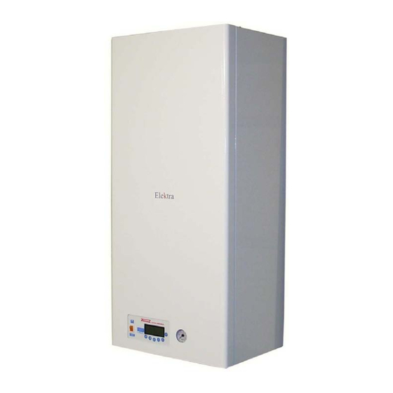
- Page 3 Dimensions The series Elektra. .. C has four power levels, but the same overall dimensions: Elektra.12 C HE 12 kW maximum electrical output Elektra.18 C HE 18 kW maximum electrical output Elektra.24 C HE 24 kW maximum electrical output Packaging dimension Appliance dimension L (Width) : Width :...
- Page 4 Hydraulic connections – Dimensional of connection arrangement. Hydraulic connections Heating delivery : ¾” Heating return : ¾” Cold sanitary water inlet : ½” Hot sanitary water output: ½” VSR Heating safety valve (3 bar) : ½” Manual Filling tap (restoring water pressure) Bottom view (under the boiler) Electrical supply...
- Page 5 Main technical features Elektra.12 C HE 12 kW maximum electrical output Single-phase electrical supply 230 V - 50 Hz. Weight : 41,5 kg. Electrical / heat power available at heating: 12 kW obtained by n°.2 resistance group (n°.2 3x2 kW). Maximum head available at the pump 5 m H Expansion vessel capacity of 10 lt.
- Page 6 Switching-on the boiler CONTROL PANEL General Display hydrometer switch Idrometro Idrometro The control panel is composed of : display, function selection keys, general switch hydrometer placed lower left corner in front of the unit (see image above). Using analogical hydrometer. The analogical hydrometer control panel has a dial with unit of measure in a bar, from 0 to 6 bar.
- Page 7 KEYBOARD PANEL (Control panel) MEANING OF THE KEYS IN USER MODE FUNCTION Display / Sanitary setpoint decrease (only if JP8 = 0) Display / Sanitary setpoint increase (only if JP8 = 0) ON - OFF Switching Display temperature output / Display setpoint output Unlock error of safety thermostat Summer –...
- Page 8 CHOICE OF THE OPERATION MODE (winter/summer) Pressing the key MODE (J4), it will be chosen the mode of operation, wintry or summery. Pressing repeatedly each time for at least 5 seconds, you switch from WINTER to SUMMER or from SUMMER to WINTER then. When the device will be in WINTER mode, on the display will appear the C C C C symbol...
- Page 9 pressure alarm, the recovery will be automatic after that the hydric pressure will be restored at the minimum operating level (0,8 bar) by means of the opening and the closure of the charging tap placed under the boiler (black handle). The display has several symbols, signaling in addition to operation modes, also the various alarm or system displays: SYMBOL...
- Page 10 INSTALLATION TECHNICAL NOTE FOR INSTALLER AND TECHNICAL MAINTENANCE HYDRAULIC SCHEME (Elektra 12 C 015 HE version) Legend - TS Safety thermostat. - rs Drain valve. - VSR Safety valve heating circuit 1/2”x3 bar. - PA Water pressure switch. - SP Brazed heat exchangers.
- Page 12 MAIN ELECTRIC SCHEME brown blue brown ON/OFF blue blu e LOVATO LOVATO blue BF09 BF09 Main P C B black black black brown Contatto brown b rown Legend electric scheme Single phase Neutral Selected Phase from Contactor Electric Pump Control of contact TS on Contactor of power (C-NO) Sanitary Microswitch (control Comfort function) Control gate triac n°1 (4KW power) Control gate triac n°2 (2KW power)
- Page 13 TRIAC – Connection scheme...
- Page 14 MANUFACTURE CONSTANTS FUNCTION Value DELTA OFF TANK PROBE 0 °C DELTA ON TANK PROBE -1 °C MAX TEMPERATURE PRIMARY 80 °C TIME OF PUMP FUNCTIONING IN ANTI-LOCK 10 sec INTERVENTION TIME ANTI-LOCK PUMP 24 H TEMPERATURE ANTIFREEZE ON (only circulator) 7 °C TEMPERATURE ANTIFREEZE ON (heat exchanger ignition) 4 °C...
- Page 15 CONTROL OF MAIN HEAT EXCHANGER According to the required power during the heat request, the controls G1-G4 related to the main exchanger are turned on all or partially. The actuation of each control is reduced to a lapse of 4 seconds. Higher is the required power, more the control will remain operative in this lapse.
- Page 16 Installation and functioning at sliding temperature For the connection of the external probe, it shall be used the Original Kit FIAMMA code F.532 provided in the accessories of the electric boilers Elektra. The electrical connection shall be done in the external terminal at the general electric panel already prearranged in the standard cabling of the boiler.
- Page 17 ANTIFREEZE FUNCTION In case the delivery probe measures a temperature lower than 7°C, the circulator is activated. If the temperature goes down the value of 4°C the main heat exchanger is ignited until the delivery temperature has reached 20°C. The antifreeze function is active also with the boiler turned OFF (function in standby mode but with bright switch on).
- Page 18 INSTRUCTION GRUNDFOS PUMP...
- Page 19 HEATING REQUEST As the contact of room thermostat closes, if the mainboard is in winter mode, the system pump is only activated if the temperature of the primary heat exchanger is higher than the temperature set by parameter N°6. If the value of temperature measured by the primary heat exchanger probe is lower than the programmed delivery setpoint, the triac are ignited in sequence as per the required power.
- Page 20 “Heating elements status” The dashes located in the upper part indicate the heating elements status. Each dash corresponds to a 2 kW element. The first 6 dashes refer to heating modules of primary heat exchanger. “Heating request” When an heating request occurs, the temperature measured by the delivery probe is I I I I displayed and the symbol starts to flash.
- Page 21 “Temperature display” On the small digit will appear the writing t : followed by the description of the selected temperature, while the big digit will show the temperature value. FUNCTION N° DELIVERY TEMPERATURE t: “Ch” SANITARY TEMPERATURE t: “Dh” EXTERNAL TEMPERATURE t: “Ep”...
- Page 22 FUNCTIONING WITH REMOTE CONTROL ENCRONO OT1, OT2 OR KRONOS OT11 LOOK OF THE REMOTE CONTROL ENCRONO OT1, OT2 OR KRONOS OT11 Elektra … C, can be connected by means of its card and an additional module to install on a prearranged part, to a compatible remote control device Opentherm®, like Encrono OT1, OT2 or Kronos OT11.
- Page 23 Parameters Table FUNCTION N° def. RANGE EXTERNAL PROBE ENABLING 0 – 1 BUILDING LEAKAGE COEFFICIENT 5 – 35 °C SANITARY POST CIRCULATION 1 – 180 sec HEATING POST CIRCULATION 1 – 180 sec HEATING EXCHANGER CIRCUL. START 0 – 240 sec MIN.
- Page 24 CONTROL PANEL IN USER MODE The pressure of one key/two keys activates the backlighting of LCD display. FUNCTION Disabled in Opentherm mode Disabled in Opentherm mode Unlock error of safety thermostat Disabled in Opentherm mode Disabled in Opentherm mode Disabled in Opentherm mode J5 + J6 Enabling of Eco/Comfort function CONTROL PANEL IN INSTALLER MODE...
-
Page 25: Spare Parts
SPARE PARTS Particular Particular: Boiler body / resistances... - Page 26 Upper particular / resistance Front unit...
- Page 27 Spare parts - Legend Upper closing fairing of Elektra .. C/N. …..…………...………. Cod.P.2127 Tetrapolar Terminal block . ………...…..………...Cod.P.2054 for Elektra 12/18 … Tetrapolar Terminal block . ………………..………... for Elektra 24 … Terminal of the electric supply line 230V (Ph). …………..….... Cod.P.2073 Terminal of the electric supply line 230V (blue - N).
- Page 28 Green Acres – Oakley Green Road – WINDSOR BERKSHIRE SL4 4QF. Tel. 01628.636099 – 01628.676900 – Fax. 01628.676958 - E-mail : euroboilerparts@hotmail.co.uk www.euroboilerparts.co.uk FIAMMA GIRO s.r.l. Company group Sede legale e stabilimento : via L. Landucci n° .2/B - 51100 PISTOIA - ITALY Tel.(+39).0573.532812 Fax.(+39).0573.532890 - E.mail : fiammaPT@fiammagiro.it...
Need help?
Do you have a question about the Combi series and is the answer not in the manual?
Questions and answers