
Related Manuals for LevelOne FCS-5041


Summary of Contents for LevelOne FCS-5041
-
Page 1: User Manual
LevelOne User Manual FCS-5041 Day/Night H.264 Megapixel PoE Outdoor Network Camera Ver 1.1... -
Page 2: General Public License
If you would like a copy of the GPL or other open source code in this software on a physical CD medium, LevelOne (Digital Data Communications) offers to mail this CD to you upon request, for a price of US$9.99 plus the cost of shipping. -
Page 3: Table Of Contents
Table of Contents Before You Use This Product ................5 Package Contents .................... 6 Overview ......................7 Device Appearance Description ................8 LED Behavior ..................... 9 Extension I/O Terminal Block ............... 9 Hardware Reset ..................... 11 Installation ....................12 Hardware installation ................12 System Requirements ................ - Page 4 Date and Time ................... 61 Save File Folder .................. 62 Device Information ................63...
-
Page 5: Before You Use This Product
Before You Use This Product The use of surveillance devices may be prohibited by law in your country. The Network Camera is not only a high-performance web-ready camera but also can be part of a flexible surveillance system. It is the user’s responsibility to ensure that the operation of such devices is legal before installing this unit for its intended use. -
Page 6: Package Contents
Package Contents Camera Bracket CD Manual/utility Power Adapter... -
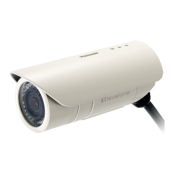
Page 7: Overview
The FCS-5041+WUA-5600 high power wireless solution can be set within any wireless coverage. With an IP67 certified outdoor enclosure, the FCS-5041 is not only weather proof, but also dust and rust resistant. By utilizing a built-in industrial fan and heater, it can perform well... -
Page 8: Device Appearance Description
Device Appearance Description... -
Page 9: Led Behavior
LED Behavior Function LED Behavior Description Remark Blinking Link Blinking while Rear Left connecting to (Orange) the network Unlit Link No connection Rear Left (Orange) Continuous Illumination Normal Rear Right Power Operation (Green) Unlit Power off Rear Right Power (Green) Extension I/O Terminal Block The Network Camera provides an extension I/O terminal block which is used to connect the camera with external input/output devices. - Page 10 DI/DO Diagram...
-
Page 11: Hardware Reset
Note - By restoring the camera, all settings will be restored to the factory default settings. USB port also support LevelOne WiFi Dongle (*) and SD/SDHC Pen-drive (*) 1) it supports LevelOne wireless outdoor USB dongle (WUA-5600) 2) it supports SD/SDHC Pen-drive (Maximum 32GB) -
Page 12: Installation
Installation Hardware installation WARNING: Do not mount the camera on a soft material. The camera may fall and be damaged. 1. Choose the location on the wall to place the camera. Use the bracket as a guide and drill four holes into the wall. Hammer the supplied plastic anchors into the holes. 2. -
Page 13: System Requirements
System Requirements Operating System: Microsoft Windows XP Home Edition SP2 Microsoft Windows XP Professional SP2 Computer: IBM PC/AT Compatible CPU: Pentium 3GHz or faster Memory: 1024 MB or more Monitor: 1024 x 768 pixels or more, 24-bit True color or better Network Interface: 10/100Mbps Network interface card must be installed Web Browser:... -
Page 14: Camera Connection
Connect the supplied power cable to the camera and plug it into a power outlet. Power over Ethernet (PoE) Connection The FCS-5041 is PoE compliant, so there are two options for connecting the camera to a power and Ethernet source. The camera can either be connected to a PoE-enabled switch or a non-PoE switch. - Page 15 B. If using a non-PoE switch: Use a standard RJ-45 cable to connect the camera to a PoE Injector. Use a standard RJ-45 cable to connect the PoE Injector to the non-PoE switch. Use a standard power cable to connect the PoE Injector to a power outlet.
-
Page 16: Software Installation
Software Installation In this manual, "User" refers to whoever has access to the Network Camera, and "Administrator" refers to the person who can configure the Network Camera and grant user access to the camera. After hardware connection checking, the users can run the Installation Wizard program included in the product CD-ROM to automatically search for the Network Camera in the Intranet. - Page 19 2. Do not check the box if user would like to check the hardware installation settings. Otherwise click “Skip the hardware installation” to skip the hardware connection checking, the program will automatically search for the Network Camera in the Intranet. Click “Start”...
- Page 20 3. Select the Network Camera from the survey list and enter the user name and password. The user name and password are assigned as “admin/admin”.
- Page 21 4. Setting the Network Camera IP address. User can either select simple mode or professional mode for network camera IP setting. If simple mode is selected, the easy configuration program will set up the connection automatically. If professional mode is selected, the user will need to configure the IP manually, The DHCP setting is recommended.
- Page 22 5. Please make sure the internet connection is ready then start to do the internet discovery, otherwise click “Skip” to finish the setting. The default domain name is MAC address; you can also register with your own name on-line. 6. After finish setting, the connection successful or fail showed. If connection failed, user can either try again or quit the installation.
- Page 23 or click “X” on the top right of the screen to finish the installation. Once installation is completed, the Administrator should proceed to the next section "Access to the Network Camera" for necessary checks and configurations.
-
Page 24: Access To The Network Camera
Access to the Network Camera Check Network Settings The Network Camera can be connected either before or immediately after software installation onto the Local Area Network. The Administrator should complete the network settings on the configuration page, including the correct subnet mask and IP address of gateway and DNS. -
Page 25: Authentication
Authentication After opening the Web browser and typing in the URL of the Network Camera, a dialogue window pops up to request a username and password. The user name and password for the Administrator are assigned as “admin/admin”. Installing plug-in For the initial access to the Network Camera in Windows, the web browser may prompt for permission to install a new plug-in for the Network Camera on the Internet Explorer. - Page 26 Microsoft Windows update for validation. Therefore, user default will not have its root certificate. If IE discovers that there is no root certificate after the user’s PC connects to the IPCam, it will automatically redirect to VeriSign Web site to download and install the latest root certificate to make the installation successfully.
-
Page 27: Live View
Live View Live View is the default page that opens when accessing the camera. Live video is displayed directly in the browser window. Stream1~2 Channels The network camera offers simultaneous several streams for optimized quality and bandwidth. Go to Configuration → Camera/ Video/Audio → Video to configure the codec compression and video resolution or refer to the Video configuration page. - Page 28 video quality. The downside of using this protocol is that the quality of its real-time effect is less than that of the UDP protocol. UDP - This protocol allows for more real-time audio and video streams. However, network packets may be lost due to network burst traffic and images may be broken. Activate UDP connection time-sensitive responses are more important than video quality.
- Page 29 Motion Detection - Enable the motion detection alert function. Mute - Turn off the sound. Talk - To communicate through the camera using the computer MIC. Default – Reset to default view settings. NOTE 1. The <Camera Control Panel> functions have no effect on the recorded video. Whatever changes are made to the <Camera Control Panel>...
-
Page 30: Configuration
Configuration Click <Configuration> on the main page to change the camera settings pages. NOTE - Only Administrators can access the Configuration page. Camera/Video/Audio Camera Profile - Select a profile from the drop-down menu to change profile settings. Brightness - Drag the bar to adjust the image brightness level. Contrast - Drag the bar to adjust the image contrast level. - Page 31 Flicker-Free - Eliminates the problem of flicker. Environment - Select outdoor or indoor mode based on the conditions. Auto Iris - Deactivate or activate Auto Iris. Mirror and Flip Mirror - Enable to horizontally reflect the display of the live video. Flip - Enable to vertically reflect the display of the live video.
- Page 32 Day & Night - Select Day & Night to schedule two profiles for day and night. Select profiles from the drop down menu for the Day and Night Profiles. Schedule – Select Schedule to schedule specific time periods for different profiles.
- Page 33 Digital Input - Select Digital Input to have the profile management controlled by an external sensor. Select profiles from the drop down menu. Profiles will change according to different trigger voltage levels. Click Apply to apply settings or Cancel to cancel changes.
-
Page 34: Video
Video The Network Camera offers several separate streams for different viewing options. Stream 1 ~ 2 Video Codec - The Network Camera offers three choices of video codec standards for real-time viewing: H.264, MPEG-4 and MJPEG. Video Resolution - Select from the drop-down menu to choose the best resolution recording settings. - Page 35 Bitrate Mode - Select the bitrate manually configure the bitrate. Set the bitrate higher for better quality. Transport- RTP: The Real-time Transport Protocol (RTP) defines a standardized packet format for delivering audio and video over IP networks. RTP with Quantization Table Header : Choose this option to explicitly include JPEG quantization table in the RTP stream [RFC 2435, section 3.1.8].
- Page 36 timestamp function and select the format and display position from the drop-down menu. Text To make a note about the camera, check “Enable” and select the display position from the drop-down menu. Enter a video description in the text box. NOTE - The video overlay will only take effect in stream 1.
-
Page 37: Audio
Audio The administrator can set up several streams for the camera for different viewing devices. The administrator can enable or disable the audio function on either stream. If audio enable is selected, select the Audio codec from the drop-down menu. Advanced Settings Camera Speaker –... -
Page 38: Network
Network IP Settings This section explains how to configure a wired network connection for the camera. There are several ways to setup the camera over the Internet: (1) obtain an available dynamic IP address assigned by a DHCP server, (2) use a static IP, or use PPPoE (Point-to-point over Ethernet). Select the desire setup mode from the IP settings drop-down menu. -
Page 39: Upnp
3. PPPoE (Point-to-point over Ethernet): Use this mode if connecting to the Internet through a DSL Line. NOTE - To utilize this feature, it requires an account provided by an Internet Service Provider. Enter the user name and password provided by the ISP. Click Apply to apply settings or Cancel to cancel changes. - Page 40 DynDNSand (2) TZO NOTE - Before utilizing this function; please apply for a dynamic domain account from a DDNS provider. DynDNS – Enable the DynDNS to allow the camera to have a fixed host and domain name. Refer to the DynDNS website (www.dyndns.com) to apply for a dynamic domain account. When an account has been created, enter the username, password and hostname.
-
Page 41: Http/Https
HTTP/HTTPS HTTP – (Hypertext Transfer Protocol) - This protocol allows for TCP protocol quality without having to open specific ports for streaming. Users inside a firewall can utilize this protocol to allow streaming data through. HTTPS - (Hypertext Transfer Protocol over SSL) - This protocol allows authentication and encrypted communication over SSL (Secure Socket Layer). -
Page 42: Multicast
Multicast Multicast sends a video stream to the multicast group address and allows multiple clients to acquire the stream at the same time by requesting a copy from the multicast group address. Therefore, multicast can effectively save Internet bandwidth. The RTSP (Real-Time Streaming Protocol) controls the delivery of streaming media. -
Page 43: Easylink
EasyLink The IP Camera is bundled with free Level1DNS service which allows users to assign a unique user name to their network camera’s IP address. There is no need to configure the router to open up ports or remember hard-to-memorize IP addresses. The default domain name is MAC address, you can also register your own name on-line but it have to check the available first. -
Page 44: Event
Event Event Settings When an event (such as unauthorized movement) occurs, the camera can be scheduled to perform certain actions. An Event Type is a set of parameters that defines these actions. This section describes how to configure the camera to perform certain actions when events occur. Click <Add Event>... - Page 45 How to Set Up an Event Schedule Event Schedule describes how and when the camera performs certain actions. 1. Check “Enable” and enter a descriptive name for the event schedule. 2. Set Event Schedule to define when the event is activated by selecting from Always (24 hours), Schedule or Recurrence pattern.
- Page 46 i. A Scheduled Event can be programmed for certain times and day. ii. Click individual boxes to schedule specific times for the camera to detect events. b. If Recurrence Pattern is selected, the following page will be displayed. - 46 -...
- Page 47 An event schedule can be programmed to recur at different times according to the user’s needs. Select the days for the event schedule to occur. Select a start time and specify the duration. 3. Define what will trigger an event to occur by selecting an option from the Event drop-down list. 4.
- Page 48 Sender - Enter the email address of the sender. iii. Recipient - Enter the email address of the recipient. To enter multiple recipients, separate each using a comma. Sender’s Name – Enter the sender’s name that will appear in the recipient’s inbox.
-
Page 49: Motion Detection
5. When complete, click Apply to save new event or Cancel to delete the event. The new event will appear on the event list. 6. To edit an event setting; select the event from the list. To remove an event setting from the list, select an event name from the list and then click <Delete Event>. -
Page 50: Digital Input (Di)
will appear. Users can use this feature as a trigger source to send photos or videos to a remote server via email or FTP. Click Apply to apply settings or Cancel to cancel changes. Digital Input (DI) The DI socket allows the IP camera to receive input from an external device. The external device should have the ability to drive voltage on the connected DI wire to the triggering voltage level in order to notify the IP camera of any event of interest. -
Page 51: Notifications
Notifications Use the tools in this section to specify what type of notification will be sent when an event occurs. The camera can send buffered images to an FTP server, Samba, Email, or HTTP. FTP Settings File Transfer Protocol (FTP) is used as an application component to automatically transfer files for program internal functions. -
Page 52: E-Mail Settings
E-mail Settings Select “Primary Email Server” option from the Server Selection drop down menu to send media files to an email server when an event is triggered. SMTP Server - Enter the server host name of the email server. SMTP Port - Enter the port number of the email server; by default, the SMTP port is set to 25. Authentication - Select the authentication type from the drop-down menu. -
Page 53: Samba Settings
Samba Settings Select this option to send the media files via a network neighborhood when an event is triggered. Server Address - Enter the IP address of the Samba server. User Name - Enter the user name of the Samba server. Password - Enter the password of the Samba server. -
Page 54: Digital Output (Do)
http://ip_address/ notification.cgi?parameter ip_address – type the IP address or host name of the HTTP host. Parameter – type the notification parameter if necessary. Example URL - http://192.168.1.1/xxxx.cgi Message - name1=value1&name2=vlaue2 Result - http://192.168.1.1/xxxx.cgi? name1=value1&name2=vlaue2 https://192.168.1.1/notification.cgi?event=MD&camera=FB-100A Message - Enter the message notification that will be sent when an event is triggered. Enter the user name and password if necessary. -
Page 55: Video Clip
Video Clip This function is used to determine when video clips will be recorded and stored after an event is triggered. Pre-alarm buffer - Images can be stored internally on the server from the time immediately preceding the trigger. Enter the desired length of time. Post-alarm buffer - Images can be stored internally on the server from the time immediately following the trigger. -
Page 56: Maintenance
Maintenance Language Select the desired language from the drop-down list. Click Apply to apply settings or Cancel to cancel changes. User Management This section explains how to enable password protection and create multiple accounts. The administrator account name is “admin”, which is permanent and cannot be deleted. Click to create an account. -
Page 57: Ip Filter
administrator privilege can change other user’s access rights and delete user accounts. Click Delete or Update to delete or modify a user’s account. ♦ Viewer - user can only access the main page for live viewing. ♦ Remote Viewer - user can only access the main page for live viewing using protocol. -
Page 58: Configuration
Configuration This feature allows the user to export/import the configuration files of the network camera. Import/Export - Click export to pop up a dialog to indicate the location and file to export. Click browse to indicate the location and file of the camera configuration and click import to import the configuration file back into the network camera. -
Page 59: Reset To Default
Reset to Default This section is used to restore the camera to default factory settings. Check the boxes to preserve the IP, Date and Time, or Language settings. Click Apply to restore the camera to default factory settings. Reboot This feature will reboot the camera. Click Apply to begin. A message will pop up asking “The device will reboot. -
Page 60: System
System System Log Log – Set up the camera to record a system log when an event is triggered. This page displays the system’s log in chronological order. The system log is stored in the camera’s buffer area and will be overwritten when the buffer area is full. Click Retrieve to retrieve the log or click Save to file to save the system log. - Page 61 Date and Time Time Zone – Select the local time zone from drop-down menu. Manual – Manually enter the date and time. Clone from PC – The camera will sync with the time, date and time zone of the computer used to modify the camera settings.
- Page 62 Save File Folder Recording folder path - The destination for saving the recording video files. Click Browse to specify the saving path. Snapshot folder path - The destination for saving the snapshot files. Click Browse to specify the saving path and select the format from the drop-down menu.
- Page 63 Device Information System Information – Displays the complete system information of the camera. Network Settings –Displays the complete network settings information of the camera. Video/Audio Settings –Displays the complete video/audio settings information of the camera.
Need help?
Do you have a question about the FCS-5041 and is the answer not in the manual?
Questions and answers