
Subscribe to Our Youtube Channel
Summary of Contents for ACG MOKE NEV 2016
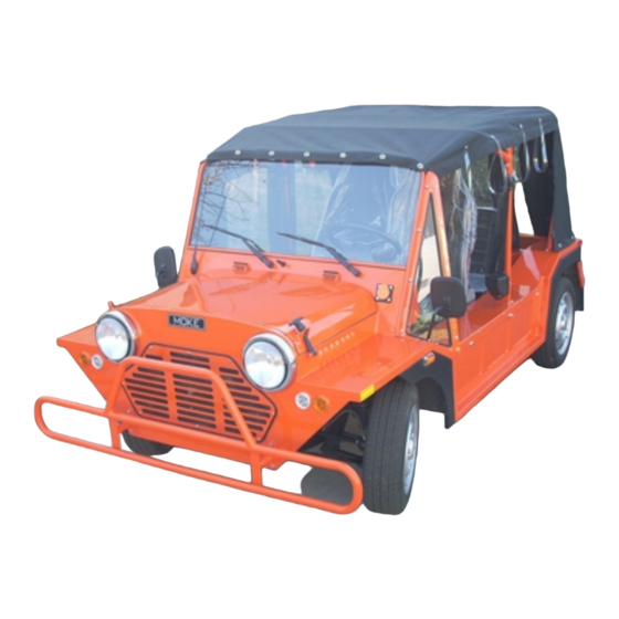
- Page 1 2016 Owner’s Manual ACG MOKE NEV Electric Low Speed Vehicle (LSV) Neighborhood Electric Vehicle (NEV) This Manual is effective as of January 31, 2016...
- Page 2 (909) 597-2885 (909) 597-7183 fax www.acgcars.us © Copyright 2016 American Custom Golf Cars, Inc. American Custom Golf Cars, Inc., ACG and MOKE Are registered trademarks of American Custom Golf Cars, Inc. Page 2 Copyright © 2016 American Custom Golf Cars, Inc.
-
Page 3: Notice
ACG is not liable for any additional requirements or modifications that your individual state may require. ACG is not liable of errors in this manual or for incidental or consequential damages that result from the use of the material in this manual. -
Page 4: Table Of Contents
Table of Contents Notice………………………………………………………………………………..… 3 Foreword…………………………………………………………………………..….. 5 Introduction………………………………………………………………………..……. 6 Insurance Notice…………………………………………………………………..…… 7 Warranty Registration………………………………………………………………..… 7 General Warnings…………………………………………………………………..….. 8 SAFE OWNERSHIP OF ACG NEV………………………………………………….. 10 Cautions, Warnings and Notes……………………………………………………..… 11 Controls and Indicators…………………………………………………………..……. 12 Switch……………………………………………………..…….……..Forward-Neutral-Reverse Shifter……………………………………..… Accelerator Pedal……………………………………………..…………….. 15 Brake Pedal…………………………………………………………..………... -
Page 5: Foreword
Foreword MOKE NEV for your Golf course and local community Thank you for choosing the transportation needs. MOKE NEV will provide Please protect your investment to make sure that your you with years of reliable performance. Your safety is important to us, so please make sure that prior to operating the vehicle you have read the following instructions and warnings. -
Page 6: Introduction
This manual is applicable to the following ACG models: ACG MOKE 2016 If any questions arise after reading the manual, please contact ACG Customer Service at (909) 597-2885. Please have your Vehicle Identification Number (VIN) and date of purchase information available. -
Page 7: Insurance Notice
“Warranty” document, and no implied warranties of merchantability or fitness to the full extent allowed by law. ACG and its dealers shall not be liable for loss of use, inconvenience, lost time, commercial loss or any incidental, consequential or other damages. -
Page 8: General Warnings
General Warnings 1. This “Owner’s Manual” should be read completely before attempting to drive or service the vehicle. Failure to follow the instructions in this manual could result in property damage, severe personal injury, or death. 2. When charging the vehicle, be sure that the key switch is in the “OFF” position. If the key is left in the “ON“... - Page 9 WARNING! 1. If renting or loaning the vehicle, make sure that the driver is familiar with all controls and operating procedures before allowing the vehicle to be driven. 2. Any modification or change to the vehicle that affects the stability or handling of the vehicle, or increases maximum vehicle speed beyond factory specifications, could result in severe personal injury or death.
-
Page 10: Safe Ownership Of Acg Nev
• ACG vehicles are designed to be recharged from a standard 120 VAC-15 Ampere electrical outlet that is ground-fault protected. Charging from a circuit of lesser capacity and/or using a cord from the outlet to the ACG vehicle that is not sufficient in wire gauge (AWG) could create a fire hazard. -
Page 11: Cautions, Warnings And Notes
• In this “Owner’s Manual”, the above safe ownership and operation habits will be pointed out to you as the different aspects of owning and operating an ACG vehicle are explained. Please read, understand and abide by them for years of safe operation and enjoyment of your ACG Vehicle. -
Page 12: Controls And Indicators
Controls and Indicators Key Switch The “Key Switch” is mounted on the right of the steering column. It has three positions: 1. OFF position- There is no power to vehicle. Key is Parallel with Steering Column as shown in Figure 1-1 2. -
Page 13: Key Switch
Figure 1-1: Key is shown in OFF position Figure 1-2: Key is shown in ACC position Figure 1-3: Key is shown in ON position WARNING! Never turn the “Key Switch” to the “OFF” position while the vehicle is in motion. This could lead to loss of speed control and loss of control of the vehicle. -
Page 14: Forward-Neutral-Reverse Shifter
Direction Control Shifter (Forward – Neutral - Reverse) The “Direction Control Shifter” is located at the center of the vehicle ahead of the Parking Brake Lever. There are three (3) distinct positions: Forward (D), Neutral (N) and Reverse (R). 1.) FORWARD (D)- To operate the vehicle in the forward direction, push the shifter forward. -
Page 15: Accelerator Pedal
Accelerator Pedal The “Accelerator Pedal” is the pedal on the right. The operation of the accelerator pedal differs from that of an Automobile. When the “Key Switch” is in the “ON” position, as the accelerator pedal is depressed speed will increase until full speed is reached. -
Page 16: Brake Pedal
Brake Pedal The “Brake Pedal” is the pedal at the center below the Steering Column it. To slow or stop the vehicle, release the “Accelerator Pedal” and then depress the brake pedal with your foot until the vehicle has come to a complete stop or the vehicle has slowed to your desired speed. -
Page 17: Park Brake
Park Brake Lever The “Park Brake Lever” is located at the center of the vehicle to the right of the driver seat. To set the “Park Brake”: Pull the “Park Brake Lever” firmly upwards. The ratcheting mechanism will automatically lock the lever in desired position. Fig. -
Page 18: Light Switch
Lights Switch The rotary “Lights Switch” is located on the left side of the Steering Column. It is identified by SAE/ISO “Lights” icons. It is the upper part of the combination lever that is also used for Turn Signal Control. It is a 3 position switch: 1.) OFF - When the top portion of the rotary switch “OFF”... - Page 19 (Fig. 5-2. - Light switch shown in “PARK” position) (Fig. 5-3. - Light switch shown in “ON” position) Page 19 Copyright © 2016 American Custom Golf Cars, Inc.
- Page 20 Lights Switch (Beam Control) The rotary “Lights Switch Beam Control” is located on the left side of the Steering Column. It is identified by SAE/ISO “Lights” icons. It is the forward and backward motion of the combination lever that is also used for Turn Signal Control.
-
Page 21: Turn Signal Lever Switch
Turn Signal Lever Switch The Turn Signals are activated by Lever Switch located on Left side of steering column below Steering Wheel. It is a 3 position switch: 1.) RIGHT - When the Lever is pushed UP ( ) – the Right Lights Flash. Clockwise 2.) OFF - When the Lever is Horizontal, the Turn Signal lights are “OFF”. -
Page 22: Turn Signal Directional Indicators
Turn Signal Directional Indicators GREEN LED Light to the Left of the Display Panel will flash when the Left Turn Signal is activated GREEN LED Light to the Right of the Display Panel will flash when the Right Turn Signal is activated Page 22 Copyright ©... -
Page 23: Hazard Warning Lights Switch
Hazard Warning Flashers The Hazard Warning Flasher Switch activates both Turn Signals to provide “Hazard Warning” by flashing both Right and Left as well as Front and Rear Turn Signals at the same time. The “Hazard” function is activated by Rocker Switch located on Top side of steering column below Steering Wheel. -
Page 24: Windshield Wipers And Washer
WINDSHIELD WIPERS AND WASHER The windshield wiper/washer lever is located on the right side of the steering column. (Windshield Wiper / Washer combination Lever) NOTE: The windshield wipers/washers will only operate with the Key Switch in the ON position. Windshield Wiper Operation There are four different modes of operation for the front windshield wipers. - Page 25 Windshield Washer Operation Pull the windshield wiper/washer lever toward the steering wheel to activate the washer. Windshield Washer Fluid Reservoir The Windshield Washer Fluid Container is located in the power-train compartment of the vehicle, open the Hood to gain access to it. It is located at the center just ahead of the Brake Fluid Reservoir.
-
Page 26: Horn
Horn The horn used for audible warning is operated by depressing the Horn Button with MOKE logo at the center of the steering wheel. Horn Button at the center of the steering wheel Page 26 Copyright © 2016 American Custom Golf Cars, Inc. -
Page 27: Windshield Defrost Blower Fan
Windshield Defrost Fan The Windshield Defroster blower fan is operated by a rocker switch located on the dashboard to the right of the steering column. The switch has 3 positions: 1.) I = FAN ON – COOL 2.) O = FAN OFF 3.) II = FAN ON - HOT When you switch the blower fan to either COOL or HOT position, you should be able to feel the air flow directed against the windshield. -
Page 28: Display Panel
Display Panel SEVCON Display Panel The MOKE NEV LCD display has following functions: Battery State of Charge (SoC) shown on bar graph at right of the screen and as percent % at top of the bar graph (shown above as 88%) ... -
Page 29: Battery Percent Charge Information On Sevcon Display
IMPORTANT INFORMATION Battery Percent Charge Information on SEVCON Display The Battery charge level indicates the relative state of charge of the Traction Battery and NOT the remaining driving range of the vehicle. Its algorithm is based on the PEAK Traction Battery Pack Voltage, which in turn calculates the APPROXIMATE charge of the Traction Battery. - Page 30 Display Screen – Other Functions Main Screen Main screen will display Direction, Speed and Battery Charge Level, it also displays Trip and Odometer (total miles) mileage traveled. If the low water battery symbol appears please check the water level in all batteries. To clear the low water battery symbol push upper arrow button 2 times;...
- Page 31 Screen VEHICLE STATUS MONITOR Section A Battery shows Battery Nominal Voltage Trac Drive Status shows current status Section B Cont. Temp. (Controller Temperature) 2. Motor Volts 3. Motor Amps 4. Motor RPM (Rotations Per Minute) 5. Motor Torque in Percent (%) These values will change as soon as you start driving the vehicle.
- Page 32 Screen VEHICLE INPUTS MONITOR on this screen all switch and input signal conditions are displayed: Forward Reverse Seat Drv Select 1 Drv Select 2 Hand Brake Foot Brake Inch FWD sw Inch REV sw Note: Drive profile #2 (Drv Select 2) is only used for testing Purpose to see the Range of motor on the controller.
- Page 33 Screen TIME TO DISTANCE This screen displays the acceleration of the vehicle from 0-1000 feet and will automatically record the performance of the vehicle. It also displays the number of hours the vehicle was driven. [8 ] To proceed to a 4 Screen push center arrow button once.
- Page 34 Screen FAULT LOG Log of all faults that have ever possibly occurred on the vehicle. The first 8 of the faults on the screen are fault checks which are created at the time the vehicle is the first programmed. button Any fault after that might be relevant.
- Page 35 Screen It will give you the date and time the fault first appeared and the explanation what the fault means. Note: You will see a sequence fault if not started in neutral this code will clear as soon as you put the car in neutral.
-
Page 36: Glove_Box
Locking Glove Box MOKE NEV is equipped with locking glove box on the dashboard. The Locking Glove Box uses the same key as the “Key Switch” as they are keyed alike. If the keys are lost, the lock for the glove box as well as the ignition switch need to be changed. -
Page 37: Rear Locking Storage Box
Rear Locking Storage Box MOKE NEV is equipped with locking storage box at the rear of the vehicle behind the Rear Seat. The Locking Storage Box uses the same key as the “Key Switch” as they are keyed alike. If the keys are lost, the lock for the glove box as well as the ignition switch need to be changed. - Page 38 Rear Storage Box Content The Rear Storage Box contains following items: 1.) Charge Cord 2.) Tire Lug Wrench 3.) Scissor type Jack 4.) Jack Handle 5.) Emergency Reflex Triangle (Rear Storage Box opened) Page 38 Copyright © 2016 American Custom Golf Cars, Inc.
-
Page 39: Front_Hood_Release
Front Hood Release MOKE NEV are located outside on The “Front Hood Release Elastics” on the both the passenger side and the driver side of the Hood. Pull on Top of the Elastic Handle and move away from the body retainer , to release the Front Hood Elastic. - Page 40 Front Hood Prop Bar MOKE The “Front Hood Prop Bar” on the NEV is located inside of the engine compartment, and at top, on the back side of the front grille. Pull on Left (when facing the vehicle) of the Bar to release it from the retaining clip.
- Page 41 CAUTION! To prevent possible damage, do not slam the hood to close it. Lower the hood until it is open approximately 4 in (10 cm), and then drop it. Never drive your vehicle unless the hood is fully closed and with both elastic latches fully engaged.
-
Page 42: Accessory Outlet
Accessory Outlet The accessory outlet is located on the dash, to the Left of the Locking Glove Box. This outlet will accept a standard automotive 12-volt accessory outlet and is only intended for moderately powered accessories, such as a cellular phone, Lap top computer, etc. -
Page 43: Master Power Switch
Master Power Switch The “Master Power Switch” is located on Left (driver side) of the vehicle just above the floor board. It has 2 positions: OFF – Red Button is pushed inwards, all electrical power is “OFF” ON – Red Button is pulled outwards, all electrical power is “ON”. (Master Power Switch) CAUTION! Do not turn the Master Power Switch OFF when vehicle is in motion,... -
Page 44: Seating
Seating Front Seats Front bucket seats for Driver and Front Passenger can be adjusted in two ways: 1.) Entire Seat can slide forward or backward 2.) The can be infinitely adjusted from full forward to full rearward recline. Front Seats Forward/Rearward Adjustment The adjusting lever lock is located at the front of the seats, near the floor on the Left side of the seat. - Page 45 Recliner Adjustment The recline lever is located on the outboard side of the seat. (Left for Driver Seat and Right for Front Passenger Seat). To recline the seat, lean forward slightly, lift the lever upward, lean back to the desired position and release the lever. To return the seatback to its normal upright position, lean forward and lift the lever.
- Page 46 CAUTION! Do not use the “Full Recline” position when vehicle is in motion ! WARNING! Adjusting a seat while driving may be dangerous ! • Moving a seat while driving could result in loss of control which could cause a collision and serious injury or death. •...
-
Page 47: Rear Seats
Rear Seats The Rear Bench seat for not more than two Rear Passengers can be adjusted in two ways: 1. The Seat Back can folded forward 2. The entire seat can be in three steps folded forward to increase cargo space. Rear Bench Seat Forward/Rearward Adjustment The position of the Rear Seat sitting cushion is fixed and can not be adjusted. - Page 48 Fold And Tumble Rear Seat NOTE: • Prior to folding the rear seat, it may be necessary to reposition the front seats. • Be sure that the front seats are fully upright and positioned forward. This will allow the rear seat to fold down easily.
- Page 49 3. Remove the wing nut. Removing the Rear Seat locking wing nut 4. Slowly flip the entire seat forward. The entire seat assembly flipped forward 5. Attach the Rear Cargo padding to the bottom of the flipped seat assembly. Using the three Velcro fastener pads at the upper edge of the padding. The Cargo Padding attached SAFETY TIPS - Transporting Passengers NEVER TRANSPORT PASSENGERS IN THE CARGO AREA.
-
Page 50: Safety_Belts
Safety Belts Your vehicle is equipped with three point “Safety Belts” for both driver and all Front and Rear passengers. Research has shown that safety belts save lives. Safety belts can reduce the seriousness of injuries in a single vehicle accident. Some of the worst injuries happen when people are thrown from the vehicle. - Page 51 Proper Use of Lap Belt Enter the vehicle and sit back. Grasp the safety belt buckle and slide the buckle up the webbing as far as necessary to make the belt go around your lap. When the safety belt is long enough to fit, insert the buckle into the latch until you hear a click.
- Page 52 SEAT BELTS AND PREGNANT WOMEN We recommend that pregnant women use seat belts throughout their pregnancy. Keeping the mother safe is the best way to keep the baby safe. Pregnant women should wear the lap part of the belt across the thighs and as snug across the hips as possible.
-
Page 53: Rear Seats
Child Restraint Everyone in your vehicle needs to be buckled up at all times - babies and children, too. Every state in the United States and all Canadian provinces require that small children ride in proper restraint systems. This is the law, and you can be prosecuted for ignoring it. - Page 54 Infants and Child Restraints Safety experts recommend that children ride rearward-facing in the vehicle until they are at least one year old and weigh at least 20 lbs (9 kg). Two types of child restraints can be used rearward-facing: infant carriers and “convertible”...
- Page 55 Before buying any restraint system, make sure that it has a label certifying that it meets all applicable Safety Standards. ACG also recommends that you try a child restraint in the vehicle seats where you will use it before you buy it.
- Page 56 Transporting Pets Pets should be restrained in a pet harness, or in a pet carrier that is secured by seat belt. Page 56 Copyright © 2016 American Custom Golf Cars, Inc.
- Page 57 Optional Accessories CAUTION! Use only ACG approved rear accessories. Others may cause damage to the vehicle, and will void warranty. WARNING! Any modifications or alterations to this vehicle could seriously affect its road worthiness and safety and may lead to an accident resulting in serious injury or death.
-
Page 58: Tires & Wheels
4. Wear Any accelerated wear of tires may be an indicator of improper alignment or poor driving habits. If uncertain, consult your ACG service provider. NOTE: The vehicle’s tire information can be found on the “Tire Information Label”... - Page 59 The tires on your new vehicle provide a balance of many characteristics. They should be inspected regularly for wear and correct inflation pressure. ACG strongly recommends that you use tires equivalent to the originals in quality and performance when replacement is needed. Failure to use equivalent replacement tires may adversely affect the safety, handling, and ride of your vehicle.
- Page 60 WARNING! • Do not use a tire, wheel size or rating other than that specified for your vehicle. • Some combinations of unapproved tires and wheels may change suspension dimensions and performance characteristics, resulting in changes to steering, handling, and braking of your vehicle. This can cause unpredictable handling and stress to steering and suspension components.
-
Page 61: Tire Changing And Jacking Points
Tire Changing & Jacking Points In the event of a flat tire, you need to observe the following precautions: Park the vehicle on a firm level surface; avoiding icy or slippery areas. Set the parking brake and block both the front and rear of the tire diagonally opposite the jacking position. - Page 62 WARNING! Getting under a jacked-up vehicle is dangerous. The vehicle could slip off the jack and fall on you. Never get any part of your body under a vehicle that is on a jack. Never start or run the motor when the vehicle is on a jack. If you need to get under the vehicle, make sure the vehicle is first located on a flat solid surface, and is supported securely by automotive jack stands or, take the vehicle to a service center where a technician can put it on a properly adjusted hoist.
-
Page 63: Brakes
If the Brake Fluid needs to be refilled more frequently than every other month then check the entire Brake System for any leakage and see your dealer for service or call immediately ACG Customer Service at (909) 597-2885 CAUTION! Brake fluid may cause damage to painted and finished surfaces. -
Page 64: Pre-Operation And Daily Safety Checklist
Pre-Operation and Daily Safety Checklist MOKE NEV is thoroughly inspected and adjusted at the factory and again Every re-inspected by your ACG Dealer before it arrives at your door. MOKE However, upon receiving your new NEV you should take time to become familiar with its controls and operation. -
Page 65: Performance Inspection
Performance Inspection After you have familiarized yourself with the operation of all the controls of the MOKE and have read and understood the driving instructions, take the vehicle for a test drive. Use the following checklist as a guide to inspect the vehicle and check daily for proper operation. -
Page 66: Driving Instructions
Driving Instructions WARNING! No person should be allowed to operate the vehicle without being instructed in the proper use and operation of the vehicle’s controls. Each first time driver should be accompanied by an experienced driver on a test drive before being allowed to operate the vehicle alone. 1. - Page 67 13. To prevent the vehicle from overturning, drive slowly straight up and down slopes. Slope exceeding 20% incline should be avoided. 14. Avoid sudden stops, sudden starts, and abrupt turns to prevent possible injury to an inattentive passenger or damage to the vehicle. 15.
-
Page 68: Starting The Vehicle
Starting the Vehicle 1. Study and understand controls. 2. Make sure everyone is seated with all parts of their body inside the vehicle. 3. Make sure everyone’s “Seat Belts” are properly fastened. 4. Make sure front wheels are turned in the desired travel direction. 5. -
Page 69: Batteries
Batteries Your MOKE is operated as a 72-volt unit with six (6) 12-Volt batteries. The batteries are specially designed and produced for use in an electric vehicle. If the batteries need to be replaced at any time for any reason, do not use automotive batteries. -
Page 70: Battery Inspection & Maintenance
Battery Inspection & Maintenance Inspection There are many tools that may help in properly caring for and maintaining batteries. Below is a list of basic items that ACG recommends for this task: Recommended Equipment: Wrench Post Cleaner ... - Page 71 CAUTION! If battery wire terminals are damaged or corroded, they should be replaced or cleaned as necessary. Failure to do so may cause them to overheat during operation. 4. Tighten all wiring connections to the proper specification (see below). Make certain there is good contact with the terminals.
-
Page 72: Cleaning
Cleaning Batteries seem to attract dust, dirt, and grime. Keeping them clean will help one spot trouble signs if they appear and avoid problems associated with grime. 1. Check that all vent caps are tightly in place. 2. Clean the battery top with a cloth or brush and a solution of baking soda and water. -
Page 73: Watering
Depending on the local climate, charging methods, application, etc. ACG recommends that batteries be checked once a month until you get a feel for how thirsty your batteries are. - Page 74 Step by step watering procedure: 1. Open the vent caps and look inside the fill wells. 2. Check electrolyte level; the minimum level is at the top of the plates. 3. If necessary add just enough water to cover the plates at this time.
-
Page 75: Charging Batteries
Charging Batteries CAUTION! Be sure that the “Key Switch” is in the “OFF” position prior to charging. 1. Your vehicle is equipped with an on board charger. To begin charging the batteries, insert a UL approved 3 prong extension cord into any 120 volt AC outlet and plug the other end into the charging cord receptacle located below the “Forward –... -
Page 76: Battery Replacement & Disposal
Contact local and/or state environmental officials regarding disposal information. You can also contact ACG Customer Service at (909) 597-2885 for information. Page 76 Copyright © 2016 American Custom Golf Cars, Inc. - Page 77 Additional Battery Service Warnings & Cautions WARNING! Always wear safety glasses or approved eye protection when servicing the vehicle. Wear a full-face shield and gloves when working with or around batteries and electrical connectors. Always use insulated tools when working with or near batteries. ...
-
Page 78: Charging Procedure
Charging Procedure GENERAL WARNINGS This “Charging Procedures” section should be read completely before attempting to charge or service the vehicle. Failure to follow the instructions in this manual could result in property damage, severe personal injury, or death. 1.) When charging the vehicle, be sure that the “Key Switch” is in the “OFF” position. - Page 79 VEHICLE CHARGING Follow the recommended “step-by-step” procedure below to re-charge the vehicle. MAIN KEY SWITCH Turn the key switch located to the right of the Steering Column fully counter- clockwise to the “OFF” position. (As Shown in Picture below) The “Key Switch” is mounted on the right of the steering column. It has three positions: 1.
- Page 80 ARKING RAKE Fully apply the parking brake by pulling the Park Brake Lever upwards. Verify that the Park Brake is in locked (PARK) position and the vehicle is stationary. (Park Brake in “PARK” position) Direction Control Switch Lever The “Direction Control Switch Lever” is a 3 position switch that is located on the floor board of the vehicle in the center.
- Page 81 AC Cord 4. Plug the AC Extension Cord into the Vehicle Charging Inlet Socket located at the Driver side of the vehicle under the Windshield. (Vehicle Charging Inlet Socket - Closed) (Vehicle Charging Inlet Socket – plugged in) CAUTION: AC Extension Cord must be of suitable length and proper AWG. (See Table T on Page XX for proper AWG wire size) 5.
- Page 82 Table T (AWG extension cable selection) Extension Cable Length Minimum AWG rating (Wire Size) 100 Feet 10 - AWG 50 Feet 12 - AWG 25 Feet 14 - AWG 12 Feet 14 - AWG 6 Feet 16 - AWG 3 Feet 16 - AWG Page 82 Copyright ©...
- Page 83 72 V SYSTEM CHARGER (TRACTION Batteries) a.) Open the Front Hood MOKE NEV are located outside on The “Front Hood Release Elastics” on the both the passenger side and the driver side of the Hood. Pull on Top of the Elastic Handle and move away from the body retainer , to release the Front Hood Elastic.
- Page 84 Check the Charger LED display a.) verify that the charger ON telltale LED (~) on the Charger is lighted. Condition YELLOW = ON b.) verify that one of the charger charge rate telltale LEDs ( I – IIIIII ) on the Charger is lighted ...
- Page 85 As charging progresses the Charge Algorithm reduces the charge rate either due to state of battery charge or due to excessive internal charger temperature. If the charging rate is reduced due to state of battery charge, one of the Yellow LEDs in the upper Six LED Ammeter section will be ON. The Yellow LED with SIX bars (IIIIII) indicates Maximum Rate of Charge –...
- Page 86 When the “80% state of Charge” is reached the Yellow LED indicating 80% charge will be lighted. Bulk charge phase is complete and the charger is now in Absorption charge phase. Charger ON (Min rate of Charge) (80% state of Charge) When Absorption charge phase is completed and the charger now enters the Finish charge phase Green LED indicating “End of Charge”...
- Page 87 (Maintenance Mode) When the “End of Charge” condition is reached the Charger will automatically switch to “Maintenance Mode”. Charger will Auto-restart if 30 days elapse or if Traction Battery Voltage drops to below 75.6 Volts. ( Voltage less than 2.1V per battery cell ) VEHICLE CHARGING ( End of Charge ) Follow the recommended step-by-step procedure after vehicle was recharged.
-
Page 88: Periodic Maintenance
Periodic Maintenance DAILY TASKS 1. Charge Batteries fully before first use of vehicle. 2. Check battery terminals for tight connections. 3. Visually inspect the tires for wear, damage, and proper inflation. 4. Check for proper operation of parking brake. 5. Check seat belts for proper operation. Page 88 Copyright ©... -
Page 89: Monthly Tasks
Periodic Maintenance MONTHLY TASKS 1. Check all six (12 Volt) Flooded batteries for proper water level. Use only Distilled Water for addition. (Not necessary if vehicle is equipped with Sealed or maintenance free Gel batteries). 2. Check battery terminals for tight connections. 3. -
Page 90: Vehicle Cleaning
To avoid spotting, do not wash your vehicle in direct sunlight. Cleaning the Seats To clean the seats of your ACG vehicle, use water or mild liquid detergent. Rubbing seats with warm water and a clean, damp cloth will also remove dirt. - Page 91 It is recommended to protect the vehicle whenever possible and preferably to store it indoors during extended non-use periods. ACG Custom Vehicle Cover is available at ACG dealerships. Page 91 Copyright © 2016 American Custom Golf Cars, Inc.
-
Page 92: Transport Or Towing
Use Tie-Down points on the frame identified with an “X” as shown on page NOTE: ACG is not responsible for damage incurred or lost items due to vehicle towing. CAUTION! TOWING THE VEHICLE IS NOT RECOMMENDED. This vehicle is not designed for dolly towing. -
Page 93: Floor Mat Safety Information
Floor Mat Safety Information Always use floor mats designed to fit the foot-well of your vehicle. Use only floor mats that leave the pedal area unobstructed and that are firmly secured so that they cannot slip out of position and interfere with the pedals or impair safe operation of your vehicle in other ways. -
Page 94: Consumer Information - Tires
Consumer Information (Tires) For further information, the 'Consumer Tire Guide' on passenger tire care, safety and mileage performance is available in the United States by writing to: Tire Industry Safety Council Box 1801 Washington, D.C. 20013 For more information on the Tire Industry Safety Council, please consult the following:... -
Page 95: Reporting Safety Defects
Consumer Information §575.6 Consumer Information Regulations; Requirements as per 49 CFR Part 575.6 Reporting Safety Defects American Custom Golf Cars, Inc. (ACG) 15740 El Prado Rd. Chino, CA 91710 USA Reporting Safety Defects If you believe that your vehicle has a defect, which could cause a crash or could cause injury or death, you should immediately inform the National Highway Traffic Safety Administration (NHTSA) in addition to notifying American Custom Golf Cars, Inc. -
Page 96: Specifications
Specifications Make Model MOKE Type NEV (Neighborhood Electric Vehicle) Emission Category ZEV (Zero Emission Vehicle) Fuel Category BEV (Battery-powered) Overall Length 2880 mm 113 Inches Overall Width 1450 mm 57 Inches Height to top of Windshield 1550 mm 61 Inches Wheelbase 2035 mm 80 Inches... - Page 97 2016 ACG MOKE NEV Manufactured by: American Custom Golf Cars, Inc. (ACG) 15740 El Prado Rd. Chino, CA 91710 USA (909) 597-2885 (909) 597-7183 fax www.acgcars.us © Copyright 2016 American Custom Golf Cars, Inc. ACG logo and MOKE Are registered trademarks of American Custom Golf Cars, Inc.
Need help?
Do you have a question about the MOKE NEV 2016 and is the answer not in the manual?
Questions and answers