Table of Contents
Advertisement
Advertisement
Table of Contents

Related Manuals for Dickinson Bristol

Summary of Contents for Dickinson Bristol
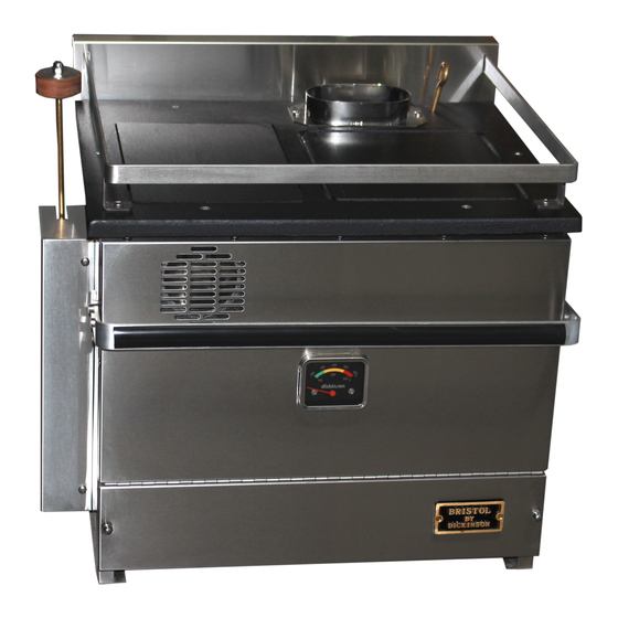
- Page 1 Natural Draft Diesel Stove Operating and Installation Instruction Manual *KEEP THIS MANUAL FOR FUTURE REFERENCE* Bristol, Bering, Pacific, Adriatic, Atlantic & Beaufort Models ** Please read from beginning to end before installing and operating. Stove Serial #: __________________...
-
Page 2: Table Of Contents
Table of Contents Table of Contents… Pg. 2 Warnings… Pg. 3 1. About a Natural Draft Diesel Stove… Pg. 4 2. Important Notes... Pg. 4 3. Ventilation… Pg. 5 4. How does the Chimney affect the Stove… Pg. 6 - Testing your Draft… Pg. 7 - Downdraft…... -
Page 3: Warnings
10. Stove Operation… Pg. 22 - Lighting Procedure… Pg. 22 11. Approximate Valve & Fan Settings… Pg. 23 - Fire Diagram… Pg. 23 12. Operation Tips… Pg. 24 - Oven Damper… Pg. 24 - Importance of the “Fuel to Air” Mixture… Pg. 25 13. -
Page 4: About A Natural Draft Diesel Stove
Dickinson diesel stove. Hot water coils are available in a 1 turn coil for all model stoves to heat approx. 5-10 gallons of water. Hot water coils are also available in 2 turn coils for all models except the Bristol stove to heat approx. 15-20 gallons of water. -
Page 5: Ventilation
• Fuel must be filtered and not exceed a pressure of 4 psi or a fuel pressure regulator must be used to avoid dangerous flooding (Dickinson part# 20-003). • A barometric damper must be installed to help regulate the draft. A barometric gives you more control in the “fuel to air”... -
Page 6: How Does The Chimney Affect The Stove
A CO alarm should be installed in the boat. We also recommend the Dickinson high heat shut-off #02-210. 4. How Does the Chimney affect the Stove? The stove does not create the draft for a natural draft appliance to operate;... -
Page 7: Testing Your Draft
3. Competition for available air. Third, there must not be too much competition from other devices in the boat, such as exhaust fans, a large engine or air-exchange systems. If something else is sucking the air out of the boat, the chimney might not be powerful enough to overcome it, and exhaust might be drawn back into the boat from the chimney. -
Page 8: Safety Clearances
There are holes located on the side to hold the repositioned valve bracket. See diagram below. This can’t be done on the Bristol model as it must face port or starboard only. This will allow the stove to operate up to 15 degrees. -
Page 9: Chimney Pipe
Chimney Pipe Diameters Bristol Stove- 4” diameter chimney (10cm) Bering, Pacific, Adriatic, Atlantic & Beaufort Stove- 5” diameter chimney (12.5cm) Barometric Damper We have 2 options for installing the barometric damper into your chimney. - Page 10 The barometric damper should be installed in oil and solid fuel stoves. The purpose is to maintain a strong draft without causing too much air to the “fuel to air” mixture. When the damper is adjusted, the draft is altered by allowing air to be pulled into the chimney by the air inlet on the damper and not pulled into the burner.
-
Page 11: Deck Fitting
A hole through the center of the block would also be 2 inches greater then the diameter of the flue pipe. *The Bristol model has a 4” diameter pipe so it would need a 6” hole. Exhaust Cap The Dickinson DP or H style exhaust caps are most recommended. -
Page 12: Stove Installation Diagram
Stove Installation Diagram Securing your Stove When installing your Dickinson stove it is recommended that you bolt it down using the 4 holes provided (2 on the bottom of each leg). The rear bolt holes can be hard to reach so instead you can use the tie down bar (provided) instead. -
Page 13: Fuel System Installation
6. Fuel System Installation For efficient and safe operation of the stove, follow all recommendations for properly installing the fuel system. DANGER: Never use gasoline in the stove. Use only #2 diesel, #1 stove oil or kerosene. The valves are factory calibrated to #2 diesel; if #1stove oil or kerosene is preferred, the valves can be re-calibrated to suit those viscosities. -
Page 14: Fuel Filter & Manual Shut-Off's
out of the valve. For this reason a manual shut-off will need to be teed in the overflow line and closed when refilling tanks. CAUTION: After refilling, you will need to burn off the fuel in the line before re-opening the shut-off valve. -
Page 15: Walbro Pump Installation
7. Walbro Fuel Pump Installation When installing a Walbro fuel pump you must ensure it is mounted approximately at the level of the valve on the stove. These pumps can “pull” fuel but have trouble “pushing” fuel so it must be gravity fed from the pump to the stove. -
Page 16: Walbro Frd-2 Pump Upgrade
& regulator. info@dickinsonmarine.com Once you have received a stronger spring and regulator from Dickinson, you can upgrade your pump to a stronger pressure. Unscrew the 3 torx screws (t- 20) and with twisting the lid back and forth, pull it straight back off. Note the pump plunger, spring, check valve, and a very small amount of fuel will drop out if installed as per diagram. -
Page 17: Exploded Fuel Pump Diagram
spring. Replace the lid with the gasket on by lowering your finger on to the red O ring sleeve without the plunger falling out (the plunger is about 2” long so you have room to lower your finger out of the way). The red O ring sleeve will fit inside the pump tube and the black O ring will fit over the outside of the pump tube and will require twisting and pushing the lid straight back in. -
Page 18: Draft Assist Fan Installation
8. Draft Assist Fan Installation The 12v draft assist is not needed for operation but highly recommended as it will help to vaporize the fuel and give more control in burning the stove as clean as possible. The fan is a 12v DC fan that the draw is .17amp. The fan is 12v and if 24v or 32v is needed, resistors are available. -
Page 19: Water Coil Installation
5-10 gallons of water. Hot water coils are also available in 2 turn coils all models except the Bristol to heat approx. 15-20 gallons of water. To plumb the hot water to the stove, ½” copper tubing should be used with the compression fittings provided. -
Page 20: Water Coil Diagrams
3. Punch 2 holes at 5/8 in diameter in the back of the combustion chamber. Your stove may have punch-outs in the back wall of the stove for the coil. If so, remove them. Use a 5/8” drill bit and drill out the cement from the back of the stove where the coil holes are. - Page 21 www.dickinsonmarine.com info@dickinsonmarine.com Form#7.2-248 Issue#2...
-
Page 22: Stove Operation
10. Operation The first time the oil-metering valve is turned on it will take 5-10 minutes for the fuel lines to fill and oil to appear in the bottom of the burner. Lighting Procedure 1. Turn on the fuel pump or open the gravity feed valve to allow fuel to flow into the oil metering valve on the stove. -
Page 23: Approximate Valve & Fan Settings
11. Approximate Valve & Fan Settings Heater Temperature Valve Setting Fan Knob Position Cold Start # 2 to # 3 Warm Low # 1 to # 2 Warm Low (cold or windy) # 2 to # 3 4 to 5 o’clock Medium # 3 to # 4 5 to 6 o’clock... -
Page 24: Operation Tips
12. Operation Tips When operating on the lower temperature settings the burner needs less air. To reduce the air, adjust the barometric damper open wider, turn off the fan, and add more fuel even if you do not want the heat. It is better to make too much heat and dissipate it than to run the burner too lean with flames inside the burner pot as this will result in hard carbon build up and soot. -
Page 25: Importance Of The "Fuel To Air" Mixture
Please visit our website and view Dickinson Marine’s Operation Video www.dickinsonmarine.com/video.html www.dickinsonmarine.com info@dickinsonmarine.com Form#7.2-248 Issue#2... -
Page 26: Flooding The Burner
5/8” from the bottom of the burner and no more for 6” burners (Bristol, Bering, Adriatic and Pacific). The 7” burners (Atlantic and Beaufort models) with a accumulate 1” of fuel from the bottom of the burner. -
Page 27: The Oil Metering Valve & Fuel Flow
14. The Oil Metering Valve & Fuel Flow Safety Fuse A high temperature fuse is incorporated into the oil metering valve. The adjusting screw on the top of the knob of the oil metering valve is fitted with a fusible sleeve. This fuse will melt if the valve knob reaches a temperature of 165 degrees F. -
Page 28: Fuel Flow Measurements
Fuel Flow Measurements If your heater is burning rich (making soot or smoking) or burning lean (flames not burning above the top burner ring), adjust the valve fuel flow as follows regardless of what type of fuel: Unscrew the compression nut from the bottom of the valve with 2 wrenches and bend away the copper fuel line. -
Page 29: Valve Operating Ranges
If the fuel is thin, run the fan more to burn off the fuel to keep a clean burn. NOTE: Bio-Diesel is not recommended for use in Dickinson diesel stove and heaters due to the extreme viscosity changes due to temperature changes and the lack of consistency available throughout the different regions. -
Page 30: Valve Repair Kits
Oil Metering Valve Repair Kits The oil metering valves have 3 generations as the size of the inside components have changed over the years. Valves from the 2006 to present generation will have a “C” stamped on the side of the valve. Before 1994: No components available (must replace valve) 1994-2006: Repair Kit part# 02-200 2006- Present: Repair Kit part# 02-200C... - Page 31 5. Clean the inside of the valve housing castings, top and bottom. Replace oil inlet screen with new and replace the inlet fitting into the top casting (use teflon tape and do not over tighten). 6. In 02-000 kit only, place the small adaptor in over the copper washer and place the new copper/brass washer over the adaptor, then screw in the new seat into the top casting until tight but not so tight as to damage the aluminum threads of the casting (35 inch pounds).
-
Page 32: Exploded Valve Diagram
Oil Metering Valve Diagram www.dickinsonmarine.com info@dickinsonmarine.com Form#7.2-248 Issue#2... -
Page 33: Burner Assembly
15. Burner Assembly The Bristol, Bering, Adriatic & Pacific model stoves has been equipped with a 6” “Airflow” burner and the Atlantic and Beaufort model stoves have a 7” “Breeze” burner. 6” Burner (Bristol, Bering, Adriatic & Pacific) There are two components in the 6” burner that must be correctly placed for the heater to operate properly. -
Page 34: 7" Burner
7” Burner (Atlantic & Beaufort) There are three components in the 7” burner that must be correctly placed for the stove to operate properly. The stainless bottom ring must be placed on the three pegs that stick out from the burner wall. The second ring is the cast iron leg ring. -
Page 35: Maintenance
16. Maintenance Fuel Maintenance Checklist (CHECK ONCE A YEAR) 1) Disconnect the fuel inlet line from the valve and place into a bucket. Turn on your pump or open your gravity feed valve to ensure there is a constant flow of fuel. This will indicate your fuel filter and fuel pump are operating correctly. -
Page 36: Cleaning The Fuel Lines
The process is the same as for a cast iron frying pan. Some Dickinson stoves have been treated with stove black. While the stove black remains on the stove, these castings should not need curing. -
Page 37: Replacement Parts
Replacement Parts *Replacement Valve: Bristol- part# 02-012, Bering, Adriatic & Pacific- part# 02-000, Atlantic- part# 02-001, Beaufort- part# 02-002 *Replacement Fan: All model stoves- part# 01-030 *Replacement 12v Fan Speed Control: All model stove- part# 01-072 *Replacement 6”... -
Page 38: Trouble Shooting
17. Trouble Shooting *Flames are burning incorrectly inside the burner pot- The flames are burning too lean, this is to say too much air and/or not enough fuel. Reduce the air intake first by adjusting the barometric damper flap open to 3/8”. This will keep the draft in the chimney strong but reduce the amount of air being drawn into the burner. - Page 39 The chimney may not be getting hot enough to create a strong draft Pg 5-7. Turn the fan on to a very slow speed but balance the fuel to keep flames above the ring Pg 18. Adjust the barometric flap so it is open between ¼ to 3/8 Pg 9.
-
Page 40: Warranty Policy
18. Warranty Policy We at Dickinson wish to maintain a reasonable and easy system for returns, warranty, returns and exchanges. To accomplish this, we would like to inform you of some helpful guidelines and procedures to use and follow when sending back product to the Dickinson Marine. - Page 41 Dickinson offers to replace said parts free of charge, provided, however, that such parts have not been improperly repaired, altered or tampered with or subjected to misuse, abuse or exposed to corrosive conditions.
- Page 42 Give name, address, and model name, location of unit, description of problem and where you can be reached during business hours. RESERVED RIGHT TO CHANGE: Dickinson reserves the right to make changes or improvements to products it produces in the future without imposing on itself any obligations to install the same improvements in the products it has previously manufactured.
-
Page 43: Registering Your Warranty
NOT FILL OUT AND MAIL THE CARD AS DIRECTED, YOU WILL NOT HAVE A WARRANTY. 19. Register your Warranty….. Please register your warranty with Dickinson Marine. Fill out and send back the warranty registration below. Make sure to include the serial # for our records. - Page 44 All rights reserved. No part of this manual may be reproduced without permission in writing from Dickinson Marine. Dickinson also reserves the right to modify or change without notice, any materials, applications, equipment, accessories, and/or prices. All measurements and weights are approximate.
Need help?
Do you have a question about the Bristol and is the answer not in the manual?
Questions and answers