Table of Contents
Advertisement
Quick Links
Installation, Operation and Maintenance Instructions
Installation,
Operation and
Maintenance
Instructions for
Mighty Therm
Hydronic Boilers
Model HH-PH
Sizes 175-400
FOR YOUR SAFETY: This product must be installed and serviced by a professional service technician,
qualified in hot water boiler installation and maintenance. Improper installation and/or operation could
create carbon monoxide gas in flue gases which could cause serious injury, property damage, or death.
Improper installation and/or operation will void the warranty.
If the information in this manual is not followed exactly, a fire or explosion may result
causing property damage, personal injury or loss of life.
Do not store or use gasoline or other flammable vapors and liquids in the vicinity of this or
any other appliance.
• Do not try to light any appliance.
• Do not touch any electrical switch; do not use any phone in your building.
• Immediately call your gas supplier from a nearby phone. Follow the gas supplier's
instructions.
• If you cannot reach your gas supplier, call the fire department.
Installation and service must be performed by a qualified installer, service agency, or gas
supplier.
WARNING
WHAT TO DO IF YOU SMELL GAS
Document 1064E
Advertisement
Table of Contents

Related Manuals for Mighty Therm HH-PH

Summary of Contents for Mighty Therm HH-PH
- Page 1 Maintenance Instructions for Mighty Therm Hydronic Boilers Model HH-PH Sizes 175-400 FOR YOUR SAFETY: This product must be installed and serviced by a professional service technician, qualified in hot water boiler installation and maintenance. Improper installation and/or operation could create carbon monoxide gas in flue gases which could cause serious injury, property damage, or death.
-
Page 2: Table Of Contents
LAARS HEATING SYSTEMS Page 2 TABLE OF CONTENTS 2F-6. Chilled Water Systems ....... 15 SECTION 1. 2F-7. System to Boiler Piping ......15 General Information 2F-8. Filling the System ........15 Introduction ........... 3 SF-9. Minimum Boiler Temperature ..... 15 Warranty ............ -
Page 3: General Information
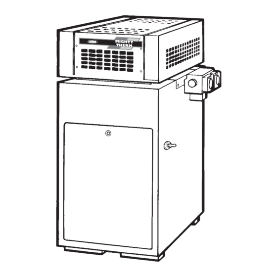
The HH-PH boilers are offered in a basic configuration (see Figure 1). On PH boilers the pump 1C. Technical Assistance is factory installed. On HH boilers the pump is field Consult Laars or your local company installed. -
Page 4: Installation Instructions
Follow local regulations with respect to installation of carbon monoxide (CO) detectors and manufacturer's maintenance schedule of the boiler. Install the HH-PH boilers in accordance with the Figure 2. Top Filler Plate. Figure 3. Adapter Plate. procedures in this manual (or the Laars warranty may be voided), local codes and ordinances. -
Page 5: Site Location
Mighty Therm HH-PH Hydronic Boilers Page 5 2C. Site Location 2C-1. Installation Information WARNING Improper installation or maintenance can cause nausea or asphyxiation from carbon monoxide in flue gases which could result in severe injury, property damage, or death. Locate the boiler to provide clearances on all sides for maintenance and inspection. -
Page 6: Outdoor Installation (U.s. Only)
Outdoor installations are not recommended in areas where the danger of snow blockage exists. 2C-3. Flooring - Typical Installation HH-PH boilers can be installed in the “low-profile,” All boilers are equipped with a special base, as a grate top configuration as received from the factory, standard part of the boiler. -
Page 7: Combustion And Ventilation Air Supply
Mighty Therm HH-PH Hydronic Boilers Page 7 Required Net Free Opening Area Directly from Outside At Top At Bottom Model Note: For screens or louvers, add 50%. Table 2. Air Openings to Outside. NOTE: Check with louver manufacturers for net Figure 14. -
Page 8: Replacement Of Existing Boiler
LAARS HEATING SYSTEMS Page 8 NOTE: Do not use sheet metal screws at the fans, including range hoods and bathroom snap lock joints of Type B gas vents. exhausts, so they will operate at maximum Do not weld or bolt the vent pipe to the boiler speed. - Page 9 Mighty Therm HH-PH Hydronic Boilers Page 9 REAR TILE COVER HEAT EXCHANGER FLOW SWITCH ASSEMBLY CONDUIT DRAIN PLUG DRAIN VALVE REAR TILE COVER GAP CLOSURE GROMMET DRAIN VALVE HEX HEAD SCREWS METAL CHANNEL MANUAL RESET (FOR CAPILLARY TUBE) HIGH LIMIT...
- Page 10 LAARS HEATING SYSTEMS Page 10 Remove the flue collector assembly by lifting it Remove the three grommets. out of the chassis. Remove the drain valve and plugs. There are two Remove the screws that fastens the gap closures hex plugs, one on the left side, and one on the and put them aside.
-
Page 11: Freeze Protection
Mighty Therm boilers. Percentage of and 6 on the terminal strip. Keep all wiring away glycol used in the Mighty Therm boiler must not from surfaces that will get hot during boiler exceed 50%. Typically, this mixture will serve as operation. - Page 12 LAARS HEATING SYSTEMS Page 12 Figure 21. Piping — Multiple Boilers, Primary Secondary System. Figure 22. Piping — Multiple Boilers, Low Temperature System.
-
Page 13: Variable Water Flow Systems
2F-4. Variable Water Flow Systems elevated water temperature. There can be reduced water flow through the Do not use the HH-PH boilers to operate on boiler in heating systems using zone valves, zone open, pressurized systems unless the supply water pumps or 3-way valves. - Page 14 LAARS HEATING SYSTEMS Page 14 Figure 24. Hydronic Piping - Primary-Secondary, Reverse-Return. Figure 25. Hydronic Piping - Primary-Secondary, Reverse-Return, Low Temperature.
-
Page 15: Chilled Water Systems
Mighty Therm HH-PH Hydronic Boilers Page 15 If a makeup water pump is used, adjust the PRESSURE pressure switch on the pumping system to FLOW RELIEF SWITCH VALVE maintain at least 12 psi (82.7 kPa) at the highest point in the heating loop. -
Page 16: Gas Supply And Piping
LAARS HEATING SYSTEMS Page 16 with CAN1-B149.1 or .2 and all local codes Distance from Gas Meter or Last Stage Regulator that apply. 0-100 feet 100-200 feet 200-300 feet Check the rating plate to make sure the boiler is 0-30 m 30-60 m 60-90 m fitted for the type of gas being used. - Page 17 Mighty Therm HH-PH Hydronic Boilers Page 17 TYPICAL WIRING DIAGRAM: IGNITION SYSTEM NO. 1 - STANDING PILOT ON/OFF OR MECHANICAL MODULATION Example shown: HH and PH Hydronic Boilers (175-250) Version B Natural or Propane Gas Figure 28. Typical Example of Wiring Schematic, System 1.
- Page 18 LAARS HEATING SYSTEMS Page 18 TYPICAL WIRING DIAGRAM: IGNITION SYSTEM NO. 12 - ELECTRONIC IGNITION ON/OFF OR MECHANICAL MODULATION Example shown: HH and PH Hydronic Boilers (325-400) Version B Natural or Propane Gas Figure 29. Typical Example of Wiring Schematic, System 12.
-
Page 19: Electrical Wiring
Mighty Therm HH-PH Hydronic Boilers Page 19 Consult local codes and fire protection authorities WARNING about specific installation restrictions. For your safety, when starting the boiler, keep your head and face well away from the lower firebox 2H. Electrical Wiring opening to prevent any risk of personal injury. -
Page 20: Start-Up Procedure
LAARS HEATING SYSTEMS Page 20 temperature drop in the system. Set the hi-limit switch Temp. 15°F (8°C) above the supply temperature to the Dial No. °F °C system. 3B. Start-Up Procedure Lighting instructions can be found on the inside of the boiler. To start up the boiler: Make sure the system pump is running and there is water flow. -
Page 21: Shut-Down Procedure
Mighty Therm HH-PH Hydronic Boilers Page 21 Flame is not lifting off the burner ports 3E. Shut-Down Procedure Shut the boiler down following the instructions Inspect the venting system for blockage, leakage, found on the inside of the boiler. and corrosion at least once a year. -
Page 22: Parts List For Hh And Ph Boilers
Figure 32). 5A. General Information NOTE: Due to sharp edges on the metal burners, To order or purchase parts for the Laars HH-PH wear protective gloves for the next steps. boilers, contact your nearest Laars dealer or 10. Hold the gas burner or pilot burner firmly, and distributor. - Page 23 Mighty Therm HH-PH Hydronic Boilers Page 23 Item Description Part Number Item Description Part Number 44. In/Out Header ELECTRICAL SYSTEM Cast Iron (S0079100), 2-Pass ...... 10593700 12. High Tension Lead ........10449513 Bronze (S0081700), 4-Pass ......10546900 13. Ignition Control (nat. Gas) ......E0094001 13.
- Page 24 LAARS HEATING SYSTEMS Page 24 (REF) Figure 33. Parts Diagram.
- Page 25 Mighty Therm HH-PH Hydronic Boilers Page 25...
- Page 26 LAARS HEATING SYSTEMS Page 26...
- Page 27 Mighty Therm HH-PH Hydronic Boilers Page 27...
- Page 28 ® Waterpik Technologies, Inc. 6000 Condor Drive, Moorpark, CA 93021 • 805.529.2000 • FAX 805.529.5934 20 Industrial Way, Rochester, NH 03867 • 603.335.6300 • FAX 603.335.3355 480 S. Service Road West, Oakville, Ontario, Canada L6K 2H4 • 905.844.8233 • FAX 905.844.2635 www.laars.com Litho in U.S.A.
Need help?
Do you have a question about the HH-PH and is the answer not in the manual?
Questions and answers