Table of Contents
Advertisement
Advertisement
Table of Contents

Related Manuals for Newtec SAT2200


Summary of Contents for Newtec SAT2200
- Page 1 Satellite Terminal Installation Guide Release 2.2 Ref. nr. 37628...
-
Page 2: Table Of Contents
Table of Contents Satellite Terminal Installation Guide Table of Contents Table of Contents ..........................2 Introduction ............................. 3 About this Guide ........................3 Material Provided in the Box ....................4 Required Installation Tools ...................... 6 Antenna Installation ........................7 Step 1: Choosing a Suitable Location ..................7 Step 2: Mounting the Antenna Pole .................. -
Page 3: Introduction
The Troubleshooting Guide, describing some possible error scenarios you might encounter during the installation of your satellite terminal, and their respective solutions (available on the CD included in the box). Copyright © 2014 Newtec Cy N.V. version 2.0 - 3 -... -
Page 4: Material Provided In The Box
Introduction Satellite Terminal Installation Guide Material Provided in the Box version 2.0 - 4 -... - Page 5 Introduction Satellite Terminal Installation Guide version 2.0 - 5 -...
-
Page 6: Required Installation Tools
Introduction Satellite Terminal Installation Guide Required Installation Tools version 2.0 - 6 -... -
Page 7: Antenna Installation
Antenna Installation Satellite Terminal Installation Guide Antenna Installation Step 1: Choosing a Suitable Location Outdoors: Antenna & iLNB • When setting up the antenna base, take into account the orientation of the antenna. Orientation data is provided by your Service Provider. •... -
Page 8: Step 2: Mounting The Antenna Pole
Antenna Installation Satellite Terminal Installation Guide Step 2: Mounting the Antenna Pole Material you have to provide yourself • A solid base for the antenna, made of concrete or firmly attached to a wall; • An antenna pole. Antenna pole requirements •... -
Page 9: Step 3: Preparing The Masthead
Antenna Installation Satellite Terminal Installation Guide Step 3: Preparing the Masthead Unfold the feed arm and fix its position by tightening the two pre-mounted screws on the masthead. version 2.0 - 9 -... -
Page 10: Step 4: Setting The Elevation Angle
Antenna Installation Satellite Terminal Installation Guide Step 4: Setting the Elevation Angle Mount the elevation adjustment bolt onto the masthead. Do not yet tighten the four elevation bolts, as the elevation angle should be set first. version 2.0 - 10 -... - Page 11 Antenna Installation Satellite Terminal Installation Guide Use the antenna pointing information provided by your Service Provider to look up the elevation angle that applies to your location, or to the city closest to your location. Using the elevation scale on the left side of the masthead, set the elevation angle to the value you have found in the antenna pointing information, by rotating the elevation adjustment bolt with the hex key.
-
Page 12: Step 5: Mounting The Antenna
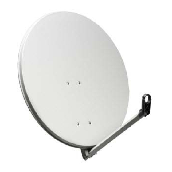
Antenna Installation Satellite Terminal Installation Guide Step 5: Mounting the Antenna Use the antenna pointing information provided by your Service Provider to look up the azimuth angle that applies to your location, or to the city closest to your location. Mount the masthead to the antenna pole, ensuring that the unfolded feed arm points to the azimuth value you have found in the antenna pointing information. - Page 13 Antenna Installation Satellite Terminal Installation Guide Secondly, mount the antenna dish onto the masthead. version 2.0 - 13 -...
- Page 14 Antenna Installation Satellite Terminal Installation Guide Thirdly, mount the iLNB clamp onto the feed arm. version 2.0 - 14 -...
-
Page 15: Step 6: Mounting The Ilnb
Antenna Installation Satellite Terminal Installation Guide Step 6: Mounting the iLNB 2.6.1 Ka-band iLNB If you have a Ka-band iLNB (ILB2210), mount it into the clamp. Ensure that the clasp at the bottom of the iLNB fits into the notch of the clamp. The two screws can be tightened. When finished, please proceed to Step 7. - Page 16 Antenna Installation Satellite Terminal Installation Guide 2.6.2 Ku-band iLNB If you have a Ku-band iLNB (ILB2110, ILB2120, ILB2140), mount it into the clamp. Do not yet tighten the two screws, as the polarization angle should be set first. version 2.0 - 16 -...
- Page 17 Antenna Installation Satellite Terminal Installation Guide Use the antenna pointing information provided by your Service Provider to look up the polarization angle that applies to your location, or to the city closest to your location. Identify the angle marker on the iLNB feedclamp as indicated in the figure below. The angle marker is in fact the line that separates the top and bottom part of the feedclamp.
- Page 18 Antenna Installation Satellite Terminal Installation Guide When the polarization angle is set, tighten the two screws to fix the polarization angle. version 2.0 - 18 -...
-
Page 19: Step 7: Connecting The Equipment
Antenna Installation Satellite Terminal Installation Guide Step 7: Connecting the Equipment 2.7.1 Preparing the Coax Cable The twin coax cable is delivered with two premounted waterproof connectors on one side. This is the outdoor end of the cable. The other side of the cable has no connectors attached yet, which allows the length of the cable to be reduced (e.g. - Page 20 Antenna Installation Satellite Terminal Installation Guide Fold the wire shielding backwards over the cable jacket. Cut away the plastic shield. Screw the F-connector to the wire by hand. The result should resemble like the figure below: Repeat this procedure for the second F-connector. version 2.0 - 20 -...
- Page 21 Antenna Installation Satellite Terminal Installation Guide 2.7.2 Grounding the iLNB The grounding kit bag can be found in the modem box. You won’t need all items contained in the grounding kit bag. Which items you actually have to use depends on your iLNB type. Ground your iLNB as indicated in the figures below.
- Page 22 Antenna Installation Satellite Terminal Installation Guide 2.7.2.2 ILB2110 and ILB2120 2.7.3 Connecting the Modem to the iLNB Connect the modem to the iLNB. Make sure to use the premounted and waterproof outdoor connectors on the iLNB. The figure below shows the connection to a Ka-band iLNB. The connection to a Ku-band iLNB is similar.
- Page 23 Antenna Installation Satellite Terminal Installation Guide 2.7.4 Connecting the Modem to your Computer Plug the network cable in the modem’s and your computer’s Ethernet ports. Use the network cable provided in the box or a cable of your choice. version 2.0 - 23 -...
- Page 24 Antenna Installation Satellite Terminal Installation Guide Connect the power adapter provided in the box to the modem and a wall outlet. The modem itself can be installed in three ways (as illustrated in the picture below): • Wall mounted (Note: screws for wall mount installation are not included); •...
-
Page 25: Terminal Installation
Terminal Installation Satellite Terminal Installation Guide Terminal Installation Before you start: The procedure below assumes: - that your computer is DHCP enabled; - that you will connect a single computer to the modem. You need to access the GUI (Graphical User Interface) of the modem. Make sure the modem is turned on and properly connected to your computer. -
Page 26: Step 1: Select Outdoor Unit
Terminal Installation Satellite Terminal Installation Guide If the software version of your modem is not 2.2.x.y (where x and y can be any number), the installation procedure can slightly differ from what is described in this manual. The software version is shown on the installation page. Please contact your Service Provider in case of problems Step 1: Select Outdoor Unit •... -
Page 27: Step 2: Select Spot Beam
Terminal Installation Satellite Terminal Installation Guide Step 2: Select Spot Beam • Select the beam identifier corresponding to your location as indicated in the antenna pointing information provided by your Service Provider, and click to continue. (Note: the screenshot below is just an example) version 2.0 - 27 -... -
Page 28: Step 3: Pointing Your Antenna
Terminal Installation Satellite Terminal Installation Guide Step 3: Pointing your Antenna Do not stand in front of the iLNB of the antenna dish during pointing. Keep the space between the iLNB and the antenna dish clear. 3.3.1 Enabling Pointing Mode on the Modem If two pointing carriers have been pre-configured, keep the pre-selected carrier. - Page 29 Terminal Installation Satellite Terminal Installation Guide 3.3.2 Setting Up the Point&Play Tool 3.3.2.1 Introduction The Point&Play tool helps you to point the antenna correctly. During the pointing procedure, the Point&Play tool can produce various sounds, each having a specific meaning described below. You will thus need to put on the headphone whenever needed during the pointing procedure.
- Page 30 Terminal Installation Satellite Terminal Installation Guide Medium or high interrupted tone The antenna points to the correct satellite but does not receive the strongest signal so far. As soon as you hear this tone, you are sure that the antenna points to the correct satellite. Low uninterrupted tone The antenna is not pointing to a satellite or points to a wrong satellite.
- Page 31 Terminal Installation Satellite Terminal Installation Guide 3.3.2.2 Using the Point&Play Tool To use the Point&Play tool: Remove the TX connector from the iLNB and connect it to the Point&Play tool. Connect the earphone to the Point&Play tool. Make sure the Point&Play tool is still switched off.
- Page 32 Terminal Installation Satellite Terminal Installation Guide 3.3.3 Rough Pointing 3.3.3.1 Vertical Pointing The correct elevation angle was already set during the installation of the antenna. Verify that the elevation angle of the masthead still corresponds to the value you have found in the antenna pointing information, and that it did not change during the assembly of the antenna (e.g.
- Page 33 Terminal Installation Satellite Terminal Installation Guide If you do not hear a high pitch tone even after adjusting the azimuth and elevation angles, please refer to the Troubleshooting Guide available on the CD. 3.3.4 Optimize Vertical Pointing (Elevation) Important note: Whenever the procedure tells you to loosen a securing bolt or nut, make sure it is just loose enough to allow the corresponding element to move freely.
- Page 34 Terminal Installation Satellite Terminal Installation Guide Optimize the elevation setting by rotating the elevation adjustment bolt, using the included hex key, until the Point&Play tool produces the highest continuous pitch tone. Secure the four elevation bolts in an alternating manner to keep the highest pitch tone. version 2.0 - 34 -...
- Page 35 Terminal Installation Satellite Terminal Installation Guide 3.3.5 Optimize Horizontal Pointing (Azimuth) Loosen the four azimuth bolts (two at the top of the masthead, two at the bottom). Optimize the azimuth setting by rotating the azimuth fine adjust bolt, using the included hex key, until the Point&Play tool produces the highest continuous pitch tone.
- Page 36 Terminal Installation Satellite Terminal Installation Guide Secure the four azimuth bolts in an alternating manner to keep the highest pitch tone. 3.3.6 Checking the Pointing Perform the following checks to make sure the antenna will resist external movements (wind...): Make sure all bolts are tightly secured. Briefly place your hand between the iLNB and the dish.
- Page 37 Terminal Installation Satellite Terminal Installation Guide Apply some pressure on the antenna to make the edges move about 3cm on the left hand side, right hand side and at the top, then release it. If the antenna is still pointed correctly, you will hear the high pitch tone again.
- Page 38 Terminal Installation Satellite Terminal Installation Guide 3.3.7 Finishing the Pointing Turn off the Point&Play tool Remove the TX cable from the Point&Play tool and reconnect it to the iLNB. Use tie-wraps to attach the cables to the feed arm. Make sure to leave some slack on the cables.
-
Page 39: Step 4: Software Download
Terminal Installation Satellite Terminal Installation Guide Step 4: Software Download The modem continuously checks for software updates. • If the software is still up to date, this step is skipped automatically. You can proceed with step 5: Validation of the Installation. •... -
Page 40: Step 5: Validation Of The Installation
Terminal Installation Satellite Terminal Installation Guide Step 5: Validation of the Installation When step 4 is completed, the following screen is shown: The modem will now check if the quality of the installation needs to be validated. This depends on your Service Provider. - Page 41 Terminal Installation Satellite Terminal Installation Guide 3.5.1 Accept Disclaimer As this validation procedure involves sensitive information such as geographical location of the terminal which is subject to legal restrictions, a disclaimer is presented. Please read the disclaimer message and indicate your acceptance by clicking 3.5.2 Enter Location The validation of your installation is based on the geographical location of your terminal.
- Page 42 Terminal Installation Satellite Terminal Installation Guide A list of one or more matching locations is displayed. Select your address from the list to view your location on a map. If your address is not listed or no results are displayed, refer to the Troubleshooting Guide on the CD.
- Page 43 Terminal Installation Satellite Terminal Installation Guide The map is used to show the area of the selected location. Zooming in or out is not possible. Click to accept and proceed. If this is not your location, refer to the Troubleshooting Guide on the CD.
- Page 44 Terminal Installation Satellite Terminal Installation Guide Click to continue or to return to the previous screen. 3.5.3 Validation Once the location is confirmed, the validation begins. When validation is successful, click to proceed. If validation fails, please refer to the Troubleshooting Guide on the CD. version 2.0 - 44 -...
-
Page 45: Finish Installation
Terminal Installation Satellite Terminal Installation Guide Finish Installation • If validation was not required by your Service Provider, the following screen is shown. Click to go to the Status Page. • If validation was required by your Service Provider and it has been successfully completed, the Status Page is already shown. - Page 46 Terminal Installation Satellite Terminal Installation Guide The terminal is ready for operation and all LED indicators on the status page are green. You are now ready to surf the internet. On-line registration may be required. Please check with your Service Provider. Please refer to the MDM2200 User Manual, describing the features and the web interface of the modem (available on the CD included in the box).
-
Page 47: Annex: Restart Installation
Annex: Restart Installation Satellite Terminal Installation Guide Annex: Restart Installation In some conditions (for example when moving the antenna to another location or upon request by your Service Provider), restarting the installation procedure is required. Select Terminal Installation in the left menu pane. ...
Need help?
Do you have a question about the SAT2200 and is the answer not in the manual?
Questions and answers