
Summary of Contents for Kinroad 650GK -2
- Page 1 650、 800、 1100GK-2 Owner’s manual (EEC) READTHISMANUALCAREFULLY IT CONTAINS IMPORTANT SAFETYINFORMATION. MINIMUM RECOMMENDED OPERATOR AGE...
- Page 2 650、800、1100GK -2 Limited Warranty The warranty policy applies to those cases where the new seller vehicle is unloaded from its shipping container, set up and delivered by authorized dealer, and under normal use and service is found to have defects in parts or workmanship under the following terms and conditions.
-
Page 3: Table Of Contents
CONTENTS Page 1. FOREWORD------------------------------------------------------------------------------------------------ 3 2. A FEW WORDS ABOUTSAFETY--------------------------------------------------------------------- 4 3. IMPORTANTSAFETY INFORMATION------------------------------------------------------------ 5 4. SAFETY LABELS----------------------------------------------------------------------------------------- 7 5. AREYOUREADY TO DRIVE? ----------------------------------------------------------------------- 8 6. IS YOUR VEHICLEREADY TO DRIVE? --------------------------------------------------------- 11 7. SAFE DRIVING PRECAUTIONS ------------------------------------------------------------------- 12 8. SPECIFICATIONS ---------------------------------------------------------------------------------------14 9. -
Page 4: Foreword
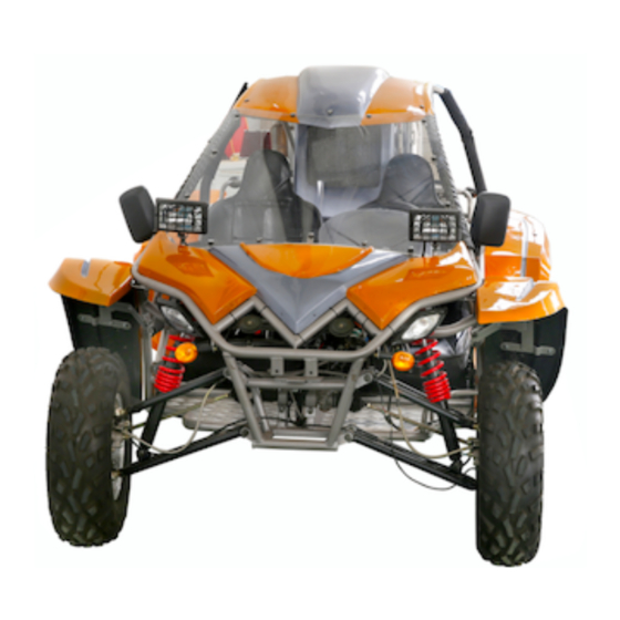
FOREWORD Thank you for choosing this Go-kart. We hope you will have fun with it. Before you start to operate the Go-Kart, please read through this Owner’s Manual carefully as it contains important safety and maintenance information. Failure to follow the warnings contained in this manual can result in serious injuries. -
Page 5: A Few Words Aboutsafety
A FORWORDS ABOUT SAFETY In order to keep everyone safe, you must take responsibility for the safe operation of your Go-Kart. To help you make informed decisions about safety, we have provided operating procedures and other information on labels and in this manual. This information alerts you to potential hazards that could hurt you or others. -
Page 6: Importantsafety Information
IMPORTANT SAFETY INFORMATION Your Go-Kart will provide you with many years of service and pleasure. Providing you take responsibility for your own safety and understand the challenges you can meet while driving. There is a lot you can do to protect yourself when you drive. You’ll find many helpful recommendations throughout this manual. -
Page 7: Important Safety Information
IMPORTANT SAFETY INFORMATION Keep away from moving parts of the Go-Kart The operator of the Go-Kart should never place their hands or other parts of their body near any moving part of the Go-Kart. Failure to adhere to this warning will cause physical harm to your body. -
Page 8: Safety Labels
SAFETY LABELS This section presents some of the most important information and recommendations to help you drive your Go-Kart safely, please take a few moments to read these pages. The labels are considered permanent parts of the Go-Kart. If a label comes off or becomes hard to read, contact your dealer for warning labels replacements. -
Page 9: Areyouready To Drive
ARE YOU READY TO DRIVE? Before each drive, you need to make sure you and your Go-Kart are both ready to drive. To help get you prepared, this section discusses how to evaluate your driving readiness, what items you should check on your Go-Kart, and adjustments to make for your comfort, convenience, or safety. -
Page 10: Are You Ready To Drive
ARE YOU READY TO DRIVE? Additional Driving Gear In addition to a helmet and eye protection, we also recommend: Sturdy off-road motorcycle boots to help protect your feet, ankles, and lower legs. ■ Off-road motorcycle gloves to help protect your hands. ■... - Page 11 ARE YOU READY TO DRIVE? No Alcohol or Drugs Alcohol, drugs and Go-Karts don’t mix. Even a small amount of alcohol can impair your ability to operate a Go-Kart safely. Likewise, drugs, even if prescribed by a physician, can be dangerous while operating a Go-Kart. Consult your doctor to be sure it is safe to operate a vehicle after taking medication.
-
Page 12: Is Your Vehicleready To Drive
IS YOUR VEHICLE READY TO DRIVE? ■ Nuts & Bolts ■ Check the wheels to see that the axle nuts are tightened, Use a wrench to make sure all accessible nuts, bolts, and fasteners are tight. Pre-drive Inspection ■ Underbody & Exhaust System ■... -
Page 13: Safe Driving Precautions
SAFE DRIVING PRECAUTIONS Keep Hands and Feet on Controls Always keep both hands on the steering wheel and both feet on the foot controls. When driving your Go-Kart. It is important to maintain your balance and control of the Go-Kart. Removing hands or feet away from the controls can reduce your ability to react and control the kart. - Page 14 SAFE DRIVING PRECAUTIONS Failure to use extra care when operating on excessi vely rough, sli ppery or loose terrain could cause loss of tracti on or vehicle control, which could result in an accident, inclu ding an overtu rn. Do not operate on excessi vely rough, sli ppery or loose terrain until you have learned an d practiced the skills necessary to control the Go-Kart on su ch terrain.
-
Page 15: Specifications
SPECIFICATIONS DIMENSIONS Overall Length---------------------------------- ----------------------------------------------------------------2800mm Overall Width ------------------------------------------------------------------------------------------------- 1900mm Overall Height -------------------------------------------------------------------------------------------------1720mm Wheelbase ------------------------------------------------------------------------------------------------------ 2050mm Front Track ---------------------------------------------------------------------------------------------------- 1400mm Rear Track ------------------------------------------------------------------------------------------------------1450mm G round Clearance ---------------------------------------------------------------------------------------------310mm SPECIFICATIONS Brake Track ----------------------------------------------------------------------------------------- < 7m @ 20miles/h Top speed ------------------------------------------------------------ 50 miles/h (or limited as customers require) CHASSIS Front, Rear brake --------------------------------------------------------------- Hydraulic disc, right foot control Front tire --------------------------------------------------------------------------------------------------------- 25×8-12... -
Page 16: Operations
OPERATION A. Operation controls WARNING Do not attempt to start or operate the engine until completely familiar with the location and use of each control necessary to operate this vehicle. The operator must know how to stop this machine before starting and driving it. a. - Page 17 OPERATION d. Start engine 1. Engage the park brake 2. Press the clutch pedal down, put the shift lever in neutral 3. Insert the key into the ignition-switch If the engine is cold; CLUTCH PEDAL BRAKE PEDAL THROTTLE PEDAL 1. Pull the choke out fully 2.
- Page 18 OPERATION e. Engine stop key Important-stop key test. Before driving this vehicle, test the Engine Stop key to assure that it is operating properly. With the engine running, turn the key counterclockwise to the “off” position for the engine to shut down. B.
- Page 19 OPERATION Passengers The vehicle allows for two riders only. Combined maximum weight of driver and the passenger should not exceed 180kg or 400Ibs. Seat Adjustment The seat must always be securely fastened in the position which best allows the operator control of the foot pedals, steering wheel, and the remote Figure 4 stop key.
- Page 20 OPERATION F. Gear ShiftAdjustment 1. Loosen the bolts. 2. Press down the clutch pedal fully. 3. Operate the shift lever as to change gearshift from 1 to 4 and reverse smoothly. 4. First, tighten bolt 1 with thread glue. Then second, tighten bolt 2 with thread glue.
-
Page 21: S Erviceinstructions
SERVICE INSTRUCTIONS A.Service Air Cleaner Service air cleaner every 80 hours NOTE: Service more often under dusty conditions. Remove cleaner cover by bolt b. Remove air cleaner element 1 (See Fig. 9) Check the paper filter, if the filter is dusty,please replace with a new one. Figure 9 B. -
Page 22: Service Instructions
SERVICE INSTRUCTIONS Check engine oil and recharge If the color of engine oil changes, you need to replace the engine oil. Replace the engine oil as above. b. Check the engine oil level, change if necessary from d as above. C. - Page 23 SERVICE INSTRUCTIONS D. Engine Coolant You must check the coolant for level and leaks. If it is low, you need to refill coolant into the radiator (approximately 4000 ml). The lack of coolant will cause the engine to overheat. This can cause engine damage. The coolant should always be topped up, since the coolant can evaporate.
- Page 24 SERVICE INSTRUCTIONS New and used coolant can be hazardous. Children and pets may be harmed by new or used coolant. Continuous or brief contact with coolant may be dangerous for your health. Keep new and used coolant away from the children and pets. To minimiz e your exposure to new and used coolant, wear a long sleeve shirt and moisture-proof gloves(such as dishwashing gloves) when you change coolant.
- Page 25 SERVICE INSTRUCTIONS F. Carburetor Adjustment Never make unnecessary adjustments. The factory recommended settings are correct for most applications. It ’s not necessary to disassemble the screw unless the carburetor needs to be replaced. Prepare a 50r/w tachometer before adjustment. a. Warm up the engine (5~10min) b.
-
Page 26: Repair
REPAIR A. Front Wheel Replacement Do not disassemble the center castle nuts when you replace the front wheels. (See Fig. 20) Tighten the nuts after replacing the wheels. Figure 20 B. Rear Wheel Replacement Do not disassemble the center castle nuts when you replace the front wheels. (See Fig. - Page 27 REPAIR C. Clutch replacement Do not remove the whole engine from vehicle when you replace the clutch, but you’ll need to remove rear suspension, driven shaft, clutch cable, muffler, wires and rubber cushion that is in the middle of transmission and frame. 1.
- Page 28 REPAIR 3. Remove two nuts (M14) on two side of transmission (See Fig. 25, 26) Figure 25 Fi gure 26 5. Remove two bolts(M8) on the low mud plate of transmission (See Fig. 27, 28) Figure 27 Figure 28 6. Remove the mud plate (See Fig. 21). Figure 29...
- Page 29 REPAIR 7. Remove the transmission (See Fig. 30, 31) Figure 30 Figure 31 8. Remove upper mud plate (See Fig. 32) Figure 32...
- Page 30 REPAIR 9. Insert a shaft into the hole (See Fig. 33). Remove six bolts on the pressing plate of clutch (See Fig. 34) Figure 33 Figure 34 10. Remove the pressure plate (See Fig. 35). Remove the friction disc of clutch (See Fig. 36, 37) Figure 35 Figure 36 Figure 37...
- Page 31 REPAIR 10. Insert a special shaft into the hole, fix new friction plate on the flywheel of engine (See Fig. 38, 39). Figure 38 Figure 39 11. Fix pressure plate of clutch. Two bolts with “Y.G” mark must be inserted into two anchor hole (See Fig.
- Page 32 REPAIR D. Timing chain Fix the timing chain n the sprocket of crankshaft. Mark A on the sprocket of crankshaft must be in the middle of double white links of timing chain. 2. Fix the guide plate.。 3. Fix the tensional plate. Fix the sprocket.
- Page 33 REPAIR E. Distributor replacement 1. turn around the crank shaft (See Fig. 44), direct the line on the pulley of crankshaft straight to the 0 degree line on the cover of engine (See Fig. 46) Figure 44 Figure 45 Figure 46 2.
- Page 34 REPAIR 3. Check the anchor hole, if it is not on the direction shown by Fig. Repeat above 1 as to obtain the hole direction shown by Fig. 4. Insert the screwdriver into the hole, turn the drive of oil pump shaft untill parallel to the crankshaft (See Fig.
- Page 35 REPAIR 6. Insert the distributor slowly to the hole (See Fig. 51). Confirm the direction of distributor is as per the figure (See Fig. 52, 53). Tighten the nut of distributor housing. Figure 51 Figure 52 Figure 53 7. Fix the cover of the distributor (See Fig. 44). Figure 42...
- Page 36 REPAIR 8. Check the spark timing. Adjust if need as followings 1. Loosen the nut of the distributor housing 2. Turn the distributor slowly. Increase the spark timing by counterclockwise turn. Decrease the spark timing by clockwise turn. F. Front Wheel Alignment a.
-
Page 37: Periodical Check And S Ervice
PERIODICAL CHECK AND SERVICES The maintenance intervals in the following table are based upon average driving conditions. Driving in unusually dusty areas, require more frequent servicing. Time of service Initial Monthly Quarterly Yearly Item service Engine 1. Fan, driven belt 2.
Need help?
Do you have a question about the 650GK -2 and is the answer not in the manual?
Questions and answers