Table of Contents
Advertisement
Safe Operation Practices • Set-Up • Operation • Maintenance • Service • Troubleshooting • Warranty
Operator's Manual
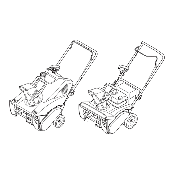
Single-Stage Snow Throwers
WARNING
READ AND FOLLOW ALL SAFETY RULES AND INSTRUCTIONS IN THIS MANUAL
BEFORE ATTEMPTING TO OPERATE THIS MACHINE.
FAILURE TO COMPLY WITH THESE INSTRUCTIONS MAY RESULT IN PERSONAL INJURY.
LES DISTRIBUTIONS RVI LIMITÉE, 2955, JEAN-BAPTISTE DESCHAMPS, LACHINE, QUEBEC H8T 1C5
MTD LLC, P.O. BOX 361131 CLEVELAND, OHIO 44136-0019
Printed In USA
769-06199
06.09.10
Advertisement
Table of Contents

Related Manuals for Columbia Single-Stage


Summary of Contents for Columbia Single-Stage
- Page 1 Safe Operation Practices • Set-Up • Operation • Maintenance • Service • Troubleshooting • Warranty Operator’s Manual Single-Stage Snow Throwers WARNING READ AND FOLLOW ALL SAFETY RULES AND INSTRUCTIONS IN THIS MANUAL BEFORE ATTEMPTING TO OPERATE THIS MACHINE. FAILURE TO COMPLY WITH THESE INSTRUCTIONS MAY RESULT IN PERSONAL INJURY.
-
Page 2: Table Of Contents
To The Owner Thank You Thank you for purchasing your new equipment. It was carefully The manufacturer reserves the right to change product engineered to provide excellent performance when properly specifications, designs and equipment without notice and operated and maintained. without incurring obligation. -
Page 3: Safe Operation Practices
Important Safe Operation Practices WARNING! This symbol points out important safety instructions which, if not followed, could endanger the personal safety and/or property of yourself and others. Read and follow all instructions in this manual before attempting to operate this machine. Failure to comply with these instructions may result in personal injury. - Page 4 Safe Handling of Gasoline Never run an engine indoors or in a poorly ventilated area. Engine exhaust contains carbon monoxide, an odorless To avoid personal injury or property damage use extreme care and deadly gas. in handling gasoline. Gasoline is extremely flammable and the Do not operate machine while under the influence of vapors are explosive.
- Page 5 Clearing a Clogged Discharge Chute According to the Consumer Products Safety Commission (CPSC) and the U.S. Environmental Protection Agency (EPA), Hand contact with the rotating impeller inside the discharge this product has an Average Useful Life of seven (7) years, chute is the most common cause of injury associated with snow or 60 hours of operation.
-
Page 6: Safety Symbols
Safety Symbols This page depicts and describes safety symbols that may appear on this product. Read, understand, and follow all instructions on the machine before attempting to assemble and operate. Symbol Description READ THE OPERATOR’S MANUAL(S) Read, understand, and follow all instructions in the manual(s) before attempting to assemble and operate WARNING—... -
Page 7: Assembly & Set-Up
Assembly & Set-Up NOTE: This Operator’s Manual covers several models. Snow thrower features may vary by model. Not all features in this manual are applicable to all snow thrower models and the snow thrower depicted may differ from yours. NOTE: All references to the left or right side of the snow thrower are from the operator’s position. -
Page 8: Controls
Controls & Features Auger Control Primer (if equipped) Chute Handle Chute Assembly Shave Plate Auger Figure 4-1 Chute Assembly NOTE: This Operator’s Manual covers several models. Snow thrower features may vary by model. Not all features in this Rotate the discharge chute to the left or right using chute handle. manual are applicable to all snow thrower models and the snow The angle of the discharge chute controls the distance that the thrower depicted may differ from yours. -
Page 9: Operation
Operation Starting & Stopping the Engine WARNING! Always keep hands and feet clear of moving parts. Do not use a pressurized starting fluid. Vapors are flammable. Refer to the Engine Operator’s manual packed with your unit for instructions on starting and stopping the engine. Engaging the Auger To engage the auger and start throwing snow, squeeze the auger control against the handle. -
Page 10: Maintenance & Adjustment
Maintenance & Adjustments Adjustments WARNING! Before servicing, repairing, or inspecting, disengage the control bail and stop engine. Removing the key will reduce the possibility of unintended starting of the engine while Side View equipment is not in use. Shave Plate Bolt To check the adjustment of the shave plate, place the machine on a level surface. - Page 11 Off-Season Storage If the snow thrower will not be used for 30 days or longer, follow the instructions below. Store the equipment in a clean, dry area. If storing the snow thrower in an unventilated area, rustproof the machine using a light oil or silicone to coat the snow thrower.
-
Page 12: Service
Service Replacing Belt Replacing Shave Plate Remove the belt cover by removing five hex screws. See Fig. 8-1. The shave plate is attached to the bottom of the auger housing Then simply pull the belt off by grasping it from the bottom of and is subject to wear. -
Page 13: Troubleshooting
Troubleshooting Problem Cause Remedy Loss of power Spark plug wire loose. Firmly connect spark plug wire. Vent in gas cap plugged. Clear vent. Excessive vibration Loose parts or damaged auger. Stop engine immediately and disconnect spark plug wire. Check for possible damage. Tighten all bolts and nuts. -
Page 14: Replacement Parts
Replacement Parts Component Part Number and Description 731-1033 Shave Plate 954-0101A Belt V-Type (2M1 Models) 954-04204 Belt V-Type (2N1 & 2P5 Models) 735-04032 Spiral Crescent 735-04033 Rubber Paddle 753-04472 Replacement Kit (includes 4 crescents, 2 paddles and hardware) 731-05632 746-04237 Clutch Cable 951-10292 Spark Plug... -
Page 15: Warranty ( For Equipment Purchased In Canada)
For equipment purchased in Canada only. THREE YEAR LIMITED WARRANTY The limited warranty set forth below is given by MTD Products Limited with respect to new merchandise purchased and used in Canada and/or its territories and possessions (either entity respectively, “MTD”). MTD warrants this product (excluding its normal wear parts as described below) against defects in material and workmanship for a period of three (3) years commencing on the date of original purchase and will, at its option, repair or replace, free of charge, any part found to be defective in materials or workmanship. -
Page 16: Warranty ( For Equipment Purchased In United States)
THREE YEARS- 120 Hrs. LIMITED WARRANTY For three (3) years-120 hrs. whichever come first, from the date of original purchase of COLUMBIA products, COLUMBIA will either repair or replace, at its option, free of charge, F.O.B. factory or authorized service firm, any part found to be defective in material and workmanship.
Need help?
Do you have a question about the Single-Stage and is the answer not in the manual?
Questions and answers
Trying to remove the auger because it broke away from the shaft just as it goes through the hole on the pulley side….all the housings have been removed (bot sides) but after all that I can’t get it through that hole on the pulley side….what do you do now it seems nothing else seems to come apart allowing it to separate
To remove a stuck auger from a Columbia Single-Stage model at the pulley side:
1. Disassemble the auger assembly.
2. Cool the assembly by placing it in a snowbank or a chest freezer overnight to shrink the metal.
3. Position the auger with the stuck rake facing up.
4. Heat the center of the rake with a torch to expand the metal.
5. Apply penetrating oil to the heated area.
6. Use a tool that fits over the shaft end and tap it with a large hammer while supporting the bottom of the shaft on a block of wood. Do not drive the rake into the gear case.
7. Once some movement is achieved, use a hydraulic press to fully remove the auger.
This answer is automatically generated