Advertisement
Quick Links
Advertisement

Related Manuals for NiCom NT3K


Summary of Contents for NiCom NT3K
- Page 1 NT3K - NT5K MEDIUM/HIGH POWER FM BROADCAST TRANSMITTER SERVICE MANUAL...
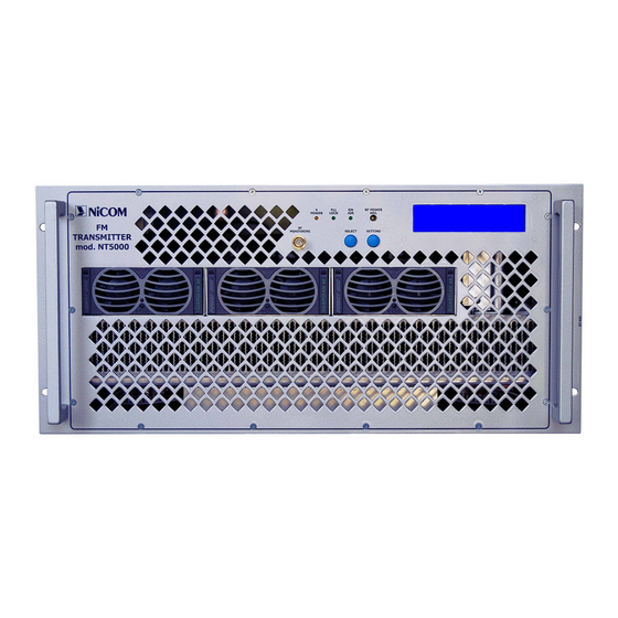
- Page 2 NT3-5K FRONT PANEL LAYOUT 3 3 4 4 1 - RF SAMPLER 1000WOUT = +10dBm 1 - RF SAMPLER 1000WOUT = +10dBm 2 - POWER STAGE SUPPLY CORRECT OPERATION YELLOWINDICATOR 2 - POWER STAGE SUPPLY CORRECT OPERATION YELLOWINDICATOR 3 - PLL LOCK FREQUENCY CONTROL CORRECT OPERATION CIRCUIT GREEN INDICATOR 3 - PLL LOCK FREQUENCY CONTROL CORRECT OPERATION CIRCUIT GREEN INDICATOR 4 - PRESENCE OF RF POWER AT FREQUENCY SET ON OUTPUT CONNECTOR GREEN INDICATOR 4 - PRESENCE OF RF POWER AT FREQUENCY SET ON OUTPUT CONNECTOR GREEN INDICATOR...
-
Page 3: Main Supply Cable
10 10 11 11 13 13 12 12 14 14 16 16 15 15 1 - MAIN SUPPLY CABLE 2-3 - FANS 4 - EARTH GROUND CONNECTING 5 - DB 9 PIN INPUT / OUTPUT CONNECTOR FOR TELEMETRY ( opt.01 ) 6-7- BNC FEMALES FOR SUBCARRIERS GENERATORS INPUTS 8-9- SCA INPUT ADJUSTING LEVELS 10-11 - COUPLE BNC FEMALE BALANCED MODE MONO AUDIO INPUT... - Page 4 Environmental Conditions for the Installation Every piece of equipment manufactured by Nicom has been carefully designed and tested in order to be in compliance with the International Normative. The reported marks placed on the rear panel and in the manual are...
- Page 5 the regular cooling air flow through the equipment. Before operating the equipment, make sure that all the recommendations reported in the manual in section 04, (“Placing the equipment in operation”) are fully complied with. In this section, the data concerning the room size where the equipment should operate are intended as minimum figures, sufficient to keep the internal parts of the equipment perfectly cooled.
- Page 6 Maintenance and Cleanliness Routine maintenance and cleaning should only take place when the equipment is not connected to the mains. Disregarding this caution, may cause problems and affect your personal safety. For no reasons, the equipment should come in contact with water or other liquids.
-
Page 7: Installation
INSTALLATION The installation of any electrical equipment should be always made by trained technicians, who are supposed to be aware of the risks related to the connection to an electrical supply. Before proceeding to the installation, it is mandatory to verify that the general electrical supply is fully in compliance with the normative of the Country where the equipment will operate. - Page 8 Disregarding the above recommendations could bring damages to the internal components and increase the risk of fire. Make sure that the equipment is placed in a stable and secure position, to easily allow the access to the front panel and to the rear panel too. This will permit in the future a simple and fast inspection of the connections if necessary.
- Page 9 the performances of the system itself. That is why we advise a 20% margin between the nominal power and the effective power. Once that everything has been verified, you can slowly increase the power up to 20% (in case of the NT5000 up to 1000W). Leave this level of power for about 20 minutes to allow all the parts to warm up and to verify that in antenna the performances are almost the same that on the Load.
- Page 10 Safety Read this chapter carefully before installation and use of the equipment. Introduction The equipment described in this manual, has been designed for use by properly trained personnel only. Adjustment, maintenance and repair of the exposed equipment should only be carried out by qualified personnel who are aware of hazards involved.
- Page 11 If adjustment, maintenance, or repair of the opened instrument is unavoidable, it must only be carried out by a skilled person who is aware of the hazards involved. Caution and Warning Statements Caution Used to indicate correct operation or maintenance in order to prevent damage to, or destruction of equipment or other property.
- Page 12 The equipment is designed for the following environmental conditions: ♦ Indoor use ♦ Altitudes up to 2000 m ♦ Temperatures between +5 C and +45 Maximum relative humidity of 95% for temperatures up to 20 The equipment is equipped with a number of input and output terminals as described in the Chapter Product Data.
- Page 13 Symbols Symbol Colour: Explanation: High voltage terminal: a terminal at which a voltage, with respect to another terminal or parts exists or may be adjusted to 1000 V or more. (High voltage > 1000 V). Black/Yellow Live part shock risk of electric shock.
- Page 14 General safety recommendations When connecting the equipment to the power, please follow these important recommendations: • This product is intended to operate from a power source that will not apply more than 10% of the voltage specified on the rear panel between the supply conductors or between either supply conductor and ground.
- Page 15 Good practices In maintaining the equipment described in this manual, please keep in mind the following, standard good practices: • When connecting any instrument (wattmeter, spectrum analyz- er, etc.) to a high frequency output, use the appropriate attenua- tor or dummy load to protect the final amplifiers and the instru- ment input.
- Page 16 First AID in case of electrical shock If someone seems unable to free himself while receiving an electric shock, turn power off before rendering aid. A muscular spasm or unconsciousness can make a victim unable to free himself from the electrical power.
- Page 17 Step 4 Put the fingertips of your hand on the Adam's apple, slide them into the groove next to the windpipe. Feel for a pulse. If you can not feel a pulse or are unsure, move on to the next step. Step 5 Position your hands in the center of the chest between the nipples.
- Page 18 • Cover burned surface with a clean dressing. • Remove all clothing from the injured area, but cut around any cloth- ing that adheres to the skin and leave it in place. Keep the patient covered, except the injured part, since there is a tendency to chill. •...
- Page 19 NICOM NT5K OPERATING INSTRUCTIONS...
- Page 20 NICOM Connect a 50 Ω load or 50 Ω antenna to the RF output. Connect the equipment into a mains supply (240 VAC) with earth point. The transmitter is factory pre-set to 0 W output power. Verify that the voltage is correct (220V single phase or 380V three phase).
- Page 21 NICOM Display Password The Password mode is factory set. The default password is 1 2 3. The WAIT of changing the password is as follows: • Press for 3 seconds the SELECT key; SELECT PASSWORD 0 1 2 3 4 5 6 7 8 9 •...
- Page 22 NICOM SELECT ERROR PASSWORD After few seconds the display will show the parameters again. • When the password is corrected the display will show: SELECT NEW PASS = SEL NEW FREQ = SET To change the password, press the SELECT key.
-
Page 23: Error Confirmation
NICOM If the confirmation password is wrong the display will show: SELECT ERROR CONFIRMATION VERY IMPORTANT NOTE ! BE AWARE ! Once the password is set, and if it is not the standard default one, you will need to remember or write down the new one. Otherwise,... - Page 24 NICOM This operation is followed by the WAIT cycle and after this the display will show the following parameters: SELECT MOD > PW 4550W PR After 7 minutes the display light switches off and the display will show: SELECT NICOM...
-
Page 25: Telemetry Connection
NT-LCD Series Transmitters DB-9 TELEMETRY CONNECTION Interlock FRW RFL TEMP MOD. -REAR VIEW- -REAR VIEW- GROUND Pin # Description Interlock ( to ground ) Forward Power Reflected Power Temperature (celsius) Modulation GROUND... - Page 26 NT5000 TOP VIEW...
- Page 27 NT5000 BOTTOM VIEW...
- Page 28 NT5000 FRONT PANEL ON NT5000 SLIDE IN/OUT POWER SUPPLIES...
- Page 29 +48V POWER SUPPLY ENABLE +48V GND EARTH +48V POWER SUPPLY ENABLE 15/25W DISPLAY +48V CONTROL PANEL GND EARTH THERMAL SWITCH NICOM MHz 98.000 LED & ADJ POWER DISPLAY +48V POWER SUPPLY ENABLE +48V N COM GND EARTH Title GENERAL SCHEMATIC Size Document Number Mod.
- Page 30 R192 R193 +24V +24V LED PW J31 E +15V Power Supply V-ADJ Protection & Meter ADJ-A +15V J32 A PUSH ADJ-B +15V ADJ-C RF DRIVER +24V LED RF RJ45 +15V LED LOCK V-ADJ LED PW +15V +24V +24V POWER DJ2x5 -15V ADJ-A ADJ-A...
- Page 31 STEREO 60pF OP275 OP275 MODULATION BF OUT LIMITER GND BF OUT SCA 1 270pF BAT43 BAT43 10pF GND SCA 1 +15V -15V 22pF SCA 2 1000MF / 25V 270pF GND SCA 2 SCA 3 100MF / 25V 270pF +15V GND SCA 3 10MF / 35V 220K R179...
- Page 32 LCD1 DISPLAY V20350 11.0592MHz 10MF / 35V 0.1MF 33pF R55 10K VU Meter R56 10K R57 10K ADC0834 33pF R58 10K Forward PW MAX810L Reflected PW SDTA SCLK D[0:7] Vref OUT ADC_EN Vref IN Temperature AGND SARS DGND 22MF / 16V 0.1MF BC327 0.1MF...
- Page 33 +15V 22uH U8 LM78S15/TO MC78M05CDT +24V 1000MF / 35V 0.1MF 10MF / 35V 0.1MF 10MF / 35V 47MF / 16V 0.1MF 0.1MF 47MF / 16V 4.7mH 0.1MF 22MF / 16V 0.1MF U20A 40106 0.1MF 1000MF / 16V TIP41C 0.1MF 22MF / 16V 0.1MF U20B 40106...
- Page 34 +24V +24V +24V +15V 10MF / 35V +15V +15V R205 100MF / 25V U12A BC327 100K LM358 BC327 LED RF R204 -15V -15V ADJ-A 0.1MF Rext 2 10MF / 35V ADJ-B RF ADJ. ADJ-C LL4148 BC337 DRIVER OFF LL4148 +24V Interlock BC327 BC337...
- Page 35 V-ADJ +15V C141 C142 0.1MF 10MF / 35V R162 R163 R164 LL4148 DRIVER OFF R165 C143 0.1MF R166 R167 R168 R169 12 R172 10 R174 10 R176 12 18T/0.4D C145 C147 C146 R170 R171 C144 4.7nF 0.1MF 10MF / 35V R173 3T/.6D 3T/.6D...
- Page 36 R120 R121 47 +15V R122 MC78M08CDT R123 47 C106 C107 C108 C110 C109 1000MF / 16V 2.2MF / 50V 2.2MF / 50V 0.1MF 1000MF / 16V R124 R125 C112 C111 0.1MF 10MF / 35V C113 0.1MF R126 R127 COAX1 RG178 J310 MV209 MV209...
- Page 37 C126 C124 C125 C127 0.1MF 10MF / 35V 22MF / 16V 0.1MF TCXO1 +15V MHz 12.800 R135 R136 R137 BC327 C134 R138 R191 R144 470MF / 25V C128 22MF / 16V C129 LL4148 LMX1501 R103 R139 R140 OSCin ØR U18A R142 LM358 OSCout...
- Page 38 NICOM Part List Schematic : ESVA-1D Rif. Value Remarks Description Code 22MF SMD Aluminium Electrolytic Capacitor 22MF SMD Aluminium Electrolytic Capacitor SMD Multilayer Ceramic Capacitor SMD Multilayer Ceramic Capacitor SMD Multilayer Ceramic Capacitor SMD Multilayer Ceramic Capacitor SMD Multilayer Ceramic Capacitor...
- Page 39 NICOM Rif. Value Remarks Description Code 22MF SMD Aluminium Electrolytic Capacitor 100MF SMD Aluminium Electrolytic Capacitor 0.1MF SMD Multilayer Ceramic Capacitor 0.1MF SMD Multilayer Ceramic Capacitor 1MF / 16V SMD Aluminium Electrolytic Capacitor 0.1MF SMD Multilayer Ceramic Capacitor SMD Aluminium Electrolytic Capacitor...
- Page 40 NICOM Rif. Value Remarks Description Code C102 10MF SMD Aluminium Electrolytic Capacitor C103 2.2MF SMD Aluminium Electrolytic Capacitor C104 10MF SMD Aluminium Electrolytic Capacitor C105 0.1MF SMD Multilayer Ceramic Capacitor C106 1000MF Aluminium Electrolytic Capacitor C107 2.2MF SMD Aluminium Electrolytic Capacitor C108 2.2MF...
- Page 41 NICOM Rif. Value Remarks Description Code C154 39pF SMD Multilayer Ceramic Capacitor C155 C156 C157 22pF SMD Multilayer Ceramic Capacitor C158 22pF SMD Multilayer Ceramic Capacitor C159 0.1MF SMD Multilayer Ceramic Capacitor C160 SMD Multilayer Ceramic Capacitor C161 47MF Aluminium Electrolytic Capacitor...
- Page 42 NICOM Rif. Value Remarks Description Code 1/4W Multi Turn Cermet Trimmer Resistor Panel Mount 1/4W SMD Thick Film Resistor 1/4W SMD Thick Film Resistor 1/4W SMD Thick Film Resistor 1/4W SMD Cermet Skeleton Trimmer Resistor 1/4W SMD Thick Film Resistor...
- Page 43 NICOM Rif. Value Remarks Description Code 1/4W SMD Cermet Skeleton Trimmer Resistor 1/4W SMD Thick Film Resistor 1/4W SMD Thick Film Resistor 1/4W SMD Thick Film Resistor 1/4W SMD Thick Film Resistor 1/4W SMD Thick Film Resistor 1/4W SMD Thick Film Resistor...
- Page 44 NICOM Rif. Value Remarks Description Code R116 1/4W SMD Thick Film Resistor R117 1/4W SMD Thick Film Resistor R118 1/4W SMD Thick Film Resistor R119 1/4W SMD Thick Film Resistor R120 1/4W SMD Thick Film Resistor R121 1/4W SMD Thick Film Resistor...
- Page 45 NICOM Rif. Value Remarks Description Code R168 1/4W SMD Thick Film Resistor R169 1/4W SMD Thick Film Resistor R170 1/4W SMD Thick Film Resistor R171 1/4W SMD Thick Film Resistor R172 1/4W SMD Thick Film Resistor R173 1/4W SMD Thick Film Resistor...
- Page 46 NICOM Rif. Value Remarks Description Code YELLOW SMD Light Emitting Diode YELLOW SMD Light Emitting Diode SMD Diode Zener LL4148 SMD Low Power Signal Diode LL4148 SMD Low Power Signal Diode SMD Diode Zener MV209 Tuning Diode MV209 Tuning Diode...
- Page 47 NICOM Rif. Value Remarks Description Code LM358 Operational Amplifier LM358 Operational Amplifier MC78M08CDT Fixed Voltage Regulator ERA6 Operational Amplifier LMX1501 Special Function Integrated Circuit LM358 Operational Amplifier LM358 Operational Amplifier CD40106 Logic Integrated Circuit 11.0592MHz Quartz Crystal TCXO1 MHz 12.800...
- Page 48 NICOM Rif. Value Remarks Description Code Jumper for setting Jumper for setting Jumper for setting...
- Page 50 TERM1 +15V 0.1 / 5W 100MF / 50V 0.1MF 10MF / 63V 0.1MF TERM2 100K REFLECTED 330 / 3W T4/W.4/D4 BA481 10MF / 63V TREE COUPLED LINE 470pF MLIN1 MLIN2 T3/W.6/D6 MLIN3 T4/W.6/D6 T4/W.6/D6 T3/W.6/D6 PD55025 BA481 39pF 10pF 39pF 33pF 100pF 68pF...
- Page 51 NICOM Part List Schematic : RF Amplifier 20W Rif. Value Remarks Description Code Ceramic Lead Through Capacitor 10MF Aluminium Electrolytic Capacitor SMD Multilayer Ceramic Capacitor 0.1MF SMD Multilayer Ceramic Capacitor 100MF Aluminium Electrolytic Capacitor 0.1MF SMD Multilayer Ceramic Capacitor Ceramic Lead Through Capacitor...
- Page 53 TERM1 +15V TERM2 BC327 TERM3 Base TIP41 TERM4 10MF/35V LM358 100nF RF ADJ BC337 10MF/35V 100nF 2.2MF/35V TERM5 +24V 220nF TERM6 LM358 INHIBIT BC327 TERM8 CTRL BC337 TERM7 N COM Title Power Control Size Document Number Mod. PWCTR-11 Date: Wednesday, June 08, 2011 Sheet...
- Page 54 NICOM Part List Schematic : PWRCTR-11 Rif. Value Remarks Description Code 10MF Aluminium Electrolytic Capacitor 100nF Polystyrene Capacitor 10MF Aluminium Electrolytic Capacitor 100nF Polystyrene Capacitor 2.2MF Aluminium Electrolytic Capacitor 220nF Polystyrene Capacitor 1/4W Metal Film Resistor 1/4W Metal Film Resistor...
- Page 61 C1 1nF +48V-1 TERM1 C2 1nF +48V-2 TERM2 C3 1nF +48V-3 TERM3 C4 1nF RF MODULE +48V-4 TERM4 C5 1nF +48-1 TERM5 FORWARD +48-2 C6 1nF +48V-5 TERM6 +48-3 FORWARD C7 1nF +48V-4 TERM7 REFLECTED REFLECTED +48V-5 C8 1nF +48V-6 TERM8 +48V-6 TERM9...
- Page 62 RF MODULE +48V-1 +48V SPLITTER-2-WAY COAX2 RG316 COAX3 RF OUTPUT RG316 RF OUTPUT-1 RF INPUT COAX5 COMBINER-2-WAY RF INPUT UT141 GATE RF OUTPUT-2 RF INPUT-1 COAX4 RF MODULE RF OUT RG316 RF INPUT-2 +48V-2 +48V COAX6 UT141 RF OUTPUT RF INPUT GATE COAX7 UT141...
- Page 63 MLIN1 LINE RF OUTPUT-1 MLIN2 LINE RF INPUT RF OUTPUT-2 MLIN3 LINE RF OUTPUT-3 N COM Title SPLITTER-3-WAY Size Document Number Mod. FMAMPL5KW Date: Thursday, July 03, 2014 Sheet...
- Page 64 MLIN4 LINE RF OUTPUT-1 100/2W RF INPUT MLIN5 LINE RF OUTPUT-2 N COM Title SPLITTER-2-WAY Size Document Number Mod. FMAMPL5KW Date: Thursday, July 03, 2014 Sheet...
- Page 65 3K3/1W 330/1W +48V LL4148 10uF/100V 100uF/35V 10uH T14/D5/W1 100pF 100nF MRFE6VP61K25H RF OUTPUT RF INPUT 27pF 39/1W LL4148 GATE 100pF N COM Title RF MODULE 1KW Size Document Number Mod. FMAMPL5KW Date: Thursday, July 03, 2014 Sheet...
- Page 66 6.8pF 8,2pF T5/D10/W2.5 RF INPUT-1 15pF 100/250W RF OUTPUT 15pF T5/D10/W2.5 RF INPUT-2 6,8pF 8,2pF N COM Title COMBINER-2-WAY Size Document Number Mod. FMAMPL5KW Date: Thursday, July 03, 2014 Sheet...
- Page 67 MLIN6 LINE RF INPUT-1 50/250W MLIN7 LINE RF INPUT-2 RF OUTPUT 50/250W 50/250W MLIN8 LINE RF INPUT-3 N COM Title COMBINER-3-WAY Size Document Number Mod. FMAMPL5KW Date: Thursday, July 03, 2014 Sheet...
- Page 68 27pF REFLECTED BAT43 uCAP uCAP TREE COUPLED LINE LINE LINE RF INPUT RF OUTPUT RF TEST uCAP uCAP uCAP 220pF BAT43 FORWARD N COM Title RF LOW PASS FILTER Size Document Number Mod. FMAMPL5KW Date: Thursday, July 03, 2014 Sheet...
- Page 69 NICOM Part List Schematic : RF AMPLIFIER 5KW Rif. Value Remarks Description Code Ceramic Lead Through Capacitor Ceramic Lead Through Capacitor Ceramic Lead Through Capacitor Ceramic Lead Through Capacitor Ceramic Lead Through Capacitor Ceramic Lead Through Capacitor Ceramic Lead Through Capacitor...
- Page 70 NICOM Rif. Value Remarks Description Code 10uH SMD Inductor T14/D5/W1 Tinned Copper Wire T5/D10/W2.5 Tinned Copper Wire T5/D10/W2.5 Tinned Copper Wire LINE LINE Metal Film Power Resistor SMD Thick Film Resistor Metal Film Power Resistor 1/4W SMD Thick Film Resistor...
- Page 71 NICOM Rif. Value Remarks Description Code COAX5 UT141 Coaxial Cable - UT141 COAX6 UT141 Coaxial Cable - UT141 COAX7 UT141 Coaxial Cable - UT141 COAX8 RG316 Coaxial Cable - RG316 COAX9 RG316 Coaxial Cable - RG316 COAX10 RG316 Coaxial Cable - RG316...
- Page 73 +12V +12V LM78L05 TERM1 +12V +48V VOUT TERM2 100uF/10V 100nF 100nF 100uF/25V Yellow Yellow Yellow +48V +12V R7 2K2 R8 2K2 ADDRESS CONN2 CONN POWER ONE ICSP CS_48V 5VAR P_DATA 5VAR ICSPCLK ICSPDAT CONN1 RS485 BAS86 5VAR N_DATA 100nF 5VAR +12V SGND_48V 100nF...
- Page 74 NICOM Part List Schematic : PSM01 Rif. Value Remarks Description Code 100uF SMD Aluminium Electrolytic Capacitor 100uF SMD Aluminium Electrolytic Capacitor 100nF SMD Multilayer Ceramic Capacitor 100nF SMD Multilayer Ceramic Capacitor 100nF SMD Multilayer Ceramic Capacitor SMD Multilayer Ceramic Capacitor...
- Page 75 NICOM Rif. Value Remarks Description Code Yellow SMD Light Emitting Diode Yellow SMD Light Emitting Diode Yellow SMD Light Emitting Diode Yellow SMD Light Emitting Diode 55C33 SMD Diode Zener 55C33 SMD Diode Zener Green SMD Light Emitting Diode SMD Light Emitting Diode...
- Page 77 DJ2x5 POWER LOCK ON AIR SELECT SETTING N COM Title Controll Panel Size Document Number Mod. FP-AMP Date: Thursday, November 03, 2011 Sheet...
- Page 78 NICOM Part List Schematic : FP-AMP Rif. Value Remarks Description Code POWER Light Emitting Diode LOCK Light Emitting Diode ON AIR Light Emitting Diode DJ2x5 Male PCB Mounting Header Multi Turn Cermet Trimmer Resistor Panel Mount SELECT Push Button Switcher...
Need help?
Do you have a question about the NT3K and is the answer not in the manual?
Questions and answers