Table of Contents
Advertisement
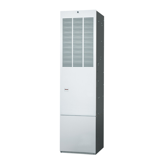
INSTALLATION INSTRUCTIONS
M7RL Series Downflow Condensing Gas Furnace
Direct Vent (Sealed Combustion) Forced Air
95.1% AFUE
For Installation in:
• Manufactured Homes
• Park Models, & Manufactured
Buildings
• Modular Homes / Buildings
WARNING:
FIRE OR EXPLOSION HAZARD
• Failure to follow safety warnings exactly
could result in serious injury or property
damage.
• Installation and service must be performed
by a qualified installer, service agency or the
gas supplier.
• Do not store or use gasoline or other
flammable vapors and liquids in the vicinity
of this or any other appliance.
WHAT TO DO IF YOU SMELL GAS
• Do not try to light any appliance.
• Do not touch any electrical switch; do not
use any phone in your building.
• Leave the building immediately.
• Immediately call your gas supplier from a
neighbor's phone. Follow the gas supplier's
instructions.
• If you cannot reach your gas supplier, call
the fire department.
DO NOT DESTROY THIS MANUAL. KEEP IN A SAFE PLACE FOR FUTURE REFERENCE.
CAUTION:
HUD Manufactured Home Construction and
Safety Standards (3280.714) prohibit the use
of noncertified air conditioning or heat pump
equipment with this furnace. It is strongly
recommended that NORDYNE manufactured
housing air conditioning components
(Intertherm or Miller brands) be selected
to provide a matched system specifically
designed to meet these requirements.
The cutting, splicing or modifying of any
internal electrical wiring may void product
warranties and create a hazardous condition.
Failure to comply with these standards could
also provide inadequate heating or cooling
performance and cause structural damage
to a manufactured home.
Please contact your local Intertherm or Miller
distributor for help. A directory of NORDYNE
factory authorized service is located in the
furnace homeowner packet.
Reference: HUD Manufactured Home
Construction and Safety Standards 3280.714.
AVERTISSEMENT:
RISQUE D'INCENDIE OU D' EXPLOSION
• Le non-respect des avertissements de
sécurité pourrait entraîner des blessures
graves, la mort ou des dommages matériels.
• L'installation et l'entretien doivent être
effectués par un installateur qualifié, un
organisme de service ou le fournisseur de
gazstaller, service agency or the gas supplier.
• Ne pas entreposer ni utiliser de l'essence ni
d'autres vapeurs ou liquides inflammables
dans le voisinage de cet appareil, ni de tout
autre appareil.
QUE FAIRE S'IL Y A UNE ODEUR DE GAZ
• Ne pas tenter d'allumer aucun appareil.
• Ne toucher à aucun interrupteur électrique;
n'utiliser aucun téléphone dans le bâtiment.
• Évacuer l'immeuble immédiatement.
• Appeler immédiatement le fournisseur de
gaz en employant le téléphone d'un voisin.
Respecter à la lettre les instructions du
fournisseur de gaz.
• Si personne ne répond, appeler le service
des incendies.
Advertisement
Table of Contents

Subscribe to Our Youtube Channel
Related Manuals for Intertherm M7RL Series


Summary of Contents for Intertherm M7RL Series
- Page 1 CAUTION: INSTALLATION INSTRUCTIONS HUD Manufactured Home Construction and M7RL Series Downflow Condensing Gas Furnace Safety Standards (3280.714) prohibit the use Direct Vent (Sealed Combustion) Forced Air of noncertified air conditioning or heat pump 95.1% AFUE equipment with this furnace. It is strongly...
-
Page 2: Table Of Contents
TABLE OF CONTENTS ELECTRICAL WIRING ..........22 IMPORTANT SAFETY INFORMATION .......3 Line Voltage Wiring ..........22 GENERAL INFORMATION ..........4 Thermostat / Low Voltage Connections ....22 Requirements & Codes ..........4 Heat Anticipator............ 23 Clearances to Combustible Materials .......5 Grounding............... 23 Combustion Air Quality..........5 START-UP &... -
Page 3: Important Safety Information
IMPORTANT SAFETY INFORMATION WARNING: INSTALLER: Please read all instructions before servicing this equipment. Pay attention to all safety warnings and ELECTRICAL SHOCK, FIRE OR EXPLOSION any other special notes highlighted in the manual. Safety HAZARD markings are used frequently throughout this manual to Failure to follow safety warnings exactly could designate a degree or level of seriousness and should result in serious injury or property damage. -
Page 4: General Information
GENERAL INFORMATION • The Commonwealth of Massachusetts requires compliance with regulation 248 CMR 4.00 and 5.00 for Requirements & Codes installation of through – the – wall vented gas appliances as follows: WARNING: 1. For direct-vent appliances, mechanical-vent heating appliances or domestic hot water equipment, where the This unit must be installed in accordance with bottom of the vent terminal and the air intake is installed instructions outlined in this manual during... -
Page 5: Clearances To Combustible Materials
Clearances to Combustible Materials The ductwork should be appropriately sized to the capacity of the furnace to ensure its proper airflow rating. For This furnace is Design Certified in the U.S. and Canada installations above 2,000 ft., the furnace should have a by CSA International for the minimum clearances to sea level input rating large enough that it will meet the combustible materials. -
Page 6: Combustion Air & Venting Requirements
COMBUSTION AIR & VENTING REQUIREMENTS WARNING: AVERTISSEMENT: RISQUE D’EMPOISONNEMENT AU CARBON MONOXIDE POISONING HAZARD MONOXYDE DE CARBONED Failure to follow the steps outlined below for each appliance connected to the venting system Le non-respect des consignes suivantes portant being placed into operation could result in carbon sur chacun des appareils raccordés au système monoxide poisoning or death.The following steps d’évacuation mis en service pourrait entraîner... -
Page 7: Important Information
Important Information Direct Vent Installation This condensing furnace is certified for installation as a WARNING: DirectVent (2-pipe) appliance.DirectVent (2-pipe) furnaces draw combustion air directly from the outdoors and then Furnace installation using methods other than vent the combustion products back outside, isolating the those described in the following sections must entire system from the indoor space.It is important to make comply with the National Fuel Gas Code (NFGC) -
Page 8: Vent Pipe Material
cause corrosion of the furnace combustion system. Maximum Direct Vent, Dual Pipe Length (FT.) (See page 5 for a sample list of substances). FURNACE MODELS INLET / OUTLET • Route piping as direct as possible between the furnace (BTU) 3” Diameter and the outdoors. -
Page 9: Outdoor Terminations - Vertical Venting
• For optimal performance, vent the furnace through a wall that experiences the least exposure to winter winds. • The vent termination shall be located at least 3 ft. horizontally from any electric meter, gas meter, regulator and any relief equipment.These distances apply ONLY to U.S. -
Page 10: Vent Freezing Protection
Vent Freezing Protection Existing Installations When an existing furnace is removed from a vent system CAUTION: serving other appliances, the existing vent system may not be sized properly to vent the remaining appliances When the vent pipe is exposed to temperatures (example: water heater). -
Page 11: Circulating Air Requirements
CIRCULATING AIR REQUIREMENTS ambient temperatures to which they will be subjected. Wiring materials located in the return duct system shall conform to Articles 300-22 of the National Electrical WARNING: Code (ANSI C1/NFPA-70). Do not allow combustion products to enter the •... -
Page 12: Closet & Alcove Installations
an external or in-wall filter mount is recommended.The • For closet installation with less than 6” front clearance, return duct should be sized to provide adequate airflow but not less than 1”, a louvered door must be used • For floor return systems, the manufactured housing having a minimum 250 in (1,613 cm ) free area opening... -
Page 13: Furnace Installation
FURNACE INSTALLATION and provided with circuit protection in accordance with local building codes.If there is any question concerning NOTE: These Installation procedures are suggested for the power supply, contact the local power company. typical furnace installations. Since each installation is √... -
Page 14: Locating & Cutting Floor Openings
Locating & Cutting Floor Openings IMPORTANT NOTE: Cut-outs in the floor, must be carefully located to avoid misalignment of the furnace. FLOOR OPENING “X” To locate standard ducts, see Figure 8. For round ducts, see Figure 9. SUPPLY AIR DUCT 1. -
Page 15: Narrow Duct Attachment - Option 1
7. Bend the connector tabs on the bottom of the duct connector upwards and as tight as possible against Hole for Gas Line the supply air duct. See Figure 11 (page 15). Tabs slide into slots in back of furnace 8. -
Page 16: Installing Screw-Down Duct Connectors
Installing Screw-Down Duct Connectors Installing the Furnace 1. Apply a bead of caulking, mastic, or other approved Sides and back of the furnace may be enclosed by wall sealant around bottom side of 1/2” flange and restrictor framing such as in a closet or alcove. The dimensions of plate (when applicable). -
Page 17: Gas Supply & Piping
GAS SUPPLY & PIPING SLIDE FURNACE WARNING: ALL THE WAY BACK ONTO MTG. PLATE FIRE OR EXPLOSION HAZARD MTG. PLATE TABS • Failure to follow safety warnings exactly could result in serious injury or property damage. • Installation and service must be performed by a qualified installer, service agency or the gas supplier. -
Page 18: Leak Check
Leak Check • All gas piping must be installed in compliance with local codes and utility regulations. In the absence of local codes the gas line installation must comply WARNING: with the latest edition of the Federal Manufactured Home Constructions & Safety Standard (H.U.D. Title FIRE OR EXPLOSION HAZARD 24, Part 3280.707[a][2]), National Fuel Gas Code Failure to follow safety warnings exactly could... -
Page 19: High-Altitude Application
High Altitude Application and using the local gas heating value. See Verifying and Adjusting the Input Rate section (page 24). High altitude conversion with this furnace depends on the installation altitude and the heating value of the gas. IMPORTANT NOTE: Observe the action of the burners Installation of this furnace at altitudes above 2,000 feet to make sure there is no yellowing, lifting or flashback shall be in accordance with local codes, or in the absence... -
Page 20: Removing The Burner Orifices
Table 10 (page 34), provides the manifold pressure for Burner Box altitudes above 2,000 feet. Gas Valve Door WARNING: Burner Box (X4) Shut off the gas supply at the manual gas shutoff valve, before disconnecting the electrical power. A fire or explosion may result causing property Orifice damage, personal injury or loss of life. -
Page 21: Lighting & Adjustment Of The Appliance
9. Remove the NPT fitting and reinstall the INLET pressure 4. Install an 1/8” NPT pipe thread fitting, that is compatible tap plug. Hand tighten the plug first to prevent cross- with a Manometer or similar pressure gauge. threading. Tighten with 3/16 Allen wrench. 5. -
Page 22: Electrical Wiring
ELECTRICAL WIRING Line Voltage Wiring • Electrical connections must be in compliance with all applicable local codes with the current revision of the WARNING: National Electric Code (ANSI/NFPA 70). • For Canadian installations the electrical connections and grounding shall comply with the current Canadian ELECTRICAL SHOCK, FIRE OR EXPLOSION Electrical Code (CSA C22.1 and/or local codes). -
Page 23: Heat Anticipator
Maximum Furnace Furnace Cabinet Nominal Maximum Minimum Maximum Minimum Fuse or Circuit Model Number Input Width Electrical Operating Operating Furnace Wire M7RL- (Btuh) (in.) Supply Voltage Voltage Amperes Gauge Breaker Amps 045A 45,000 19 7/8 115-60-1 10.0 060A 60,000 19 7/8 115-60-1 10.0 072A... -
Page 24: Start-Up & Adjustments
START-UP & ADJUSTMENTS Example: Pre-Start Check List • Time for 1 revolution of a gas meter with a 1 cubic ft dial = 40 seconds. √ Verify the polarity of the connections are correct, the • From Table 8 read 90 cubic ft gas per hr. line voltage power leads are securely connected and •... -
Page 25: Verifying Burner Operation
Verifying Operation of the Supply Air Limit NOTE: This furnace is designed to operate with a maximum external pressure rise of 0.3 inches of water Switch column.It is important that the duct system be designed Note: A properly functioning limit switch should turn off to provide the correct flow rates and external pressure the gas valve when the return is blocked (time depends rise. -
Page 26: Heating/Cooling Cycles/Fan Mode
OPERATING SEQUENCE MAINTENANCE The operating sequences for the heating, cooling, and Proper maintenance is most important to achieve the best fan modes are described below. Refer to the field and performance from a furnace. Follow these instructions for furnace wiring diagrams: (Figure 21, page 23) and (Figure years of safe, trouble free operation. -
Page 27: Air Filters
• To achieve the best performance and minimize 6. Remove the piping between the gas valve and the equipment failure it is recommended that a yearly ground-joint union. (If applicable). maintenance checkup be performed. At a minimum, 7. Remove 6 screws securing the burner box door. See this check should include the following items: Figure 19 (page 20). -
Page 28: Troubleshooting
TROUBLESHOOTING DESCRIPTION OF COMPONENTS The descriptions below are various functional components If the furnace fails to operate check the following: that affect the operation and shutting down of this furnace. • Is the thermostat operating properly? Some of these components and their locations are shown •... -
Page 29: Figures & Tables
FIGURES & TABLES Furnace Dimensions 17 3/4 Knockouts (x4) 15 1/2 2 1/2 x 5 3 1/2 (Ventilaire) (X2) 2 3/4 2 5/8 1 1/2 18 1/2 18 1/2 1 1/2 Knockouts (x4) Knockouts (x4) 18 1/2 18 1/2 20 1/4 17 1/8 2 3/4 (Electric) - Page 30 17 3/4 Knockouts (x4) 15 1/2 2 1/2 x 5 3 1/2 (Ventilaire) (X2) 2 3/4 2 5/8 1 1/2 18 1/2 18 1/2 1 1/2 Knockouts (x4) Knockouts (x4) 18 1/2 18 1/2 20 1/4 17 1/8 2 3/4 (Electric) 3 1/2 1 7/8...
- Page 31 19 3/4 15 1/2 2 1/2 x 5 (Ventilaire) 3 1/2 (X2) 2 3/4 2 5/8 1 1/2 1 1/2 18 1/2 18 1/2 Knockouts (x4) Knockouts (x4) 18 1/2 18 1/2 2 3/4 (Electric) 1 1/2 X 3 1/2 1 1/2 X 3 1/2 (Gas) (Gas)
-
Page 32: Wiring Diagram
WIRING DIAGRAM HIGH XFMR R C Y G W Figure 26. M7RL Wiring Diagram... -
Page 33: Gas Information
GAS INFORMATION GAS FLOW RATES GAS FLOW RATES CUBIC FEET PER CUBIC FEET PER TIME FOR TIME FOR REVOLUTION OF GAS METER REVOLUTION OF GAS METER ONE REVOLUTION ONE REVOLUTION (SECONDS) (SECONDS) 1,800 3,600 1,500 3,000 1,286 2,571 1,125 2,250 1,000 2,000 1,800... -
Page 34: Table 10 - High Altitude Deration Chart For Propane Gas
ALTITUDE ABOVE SEA LEVEL (FEET) Furnace Furnace 0 to 1,999 2,000 to 2,999 3,000 to 4,999 5,000 to 5,999 6,000 to 7,999 8,000 to 10,000 Model Input M7RL (Btuh) Orifice Manifold Orifice Manifold Orifice Manifold Orifice Manifold Orifice Manifold Orifice Manifold Size Pressure... -
Page 35: Venting Information
VENTING INFORMATION VENT TERMINAL AIR SUPPLY INLET AREA WHERE TERMINAL IS NOT PERMITTED CANADIAN INSTALLATIONS US INSTALLATIONS Direct Vent (2-pipe) & Clearance Location Direct Vent Conventional Vent Conventional Vent (1-pipe) (2-pipe) Furnaces (1-pipe) Furnaces Furnaces Clearance above grade, veranda, porch, deck, 12 inches (30cm) 12 inches (30cm) 12 inches (30cm) -
Page 36: Figure 27 - Horizontal & Vertical Venting
VERTICAL VENTING HORIZONTAL VENTING Seal/Caulk Straps or Other Suitable Around Pipes Supports at minimum of 5 ft. Intervals Support System on at Building Vertical Rise 90° 90° Elbow Elbow 90° Elbow Upward Pitch - 1/4” per foot 12” Min. (Flue Pipe) 7”... -
Page 40: Installation / Performance Checklist
INSTALLATION / PERFORMANCE CHECK LIST ELECTRICAL SYSTEM: ATTENTION INSTALLERS: It is your responsibility to know this product better than your customer. Electrical connections tight? This includes being able to install the product according to strict safety guidelines and instructing the customer on how to operate Line voltage polarity correct? and maintain the equipment for the life of the product.
Need help?
Do you have a question about the M7RL Series and is the answer not in the manual?
Questions and answers