
Related Manuals for Dualsky Breeze Pro Evo

Summary of Contents for Dualsky Breeze Pro Evo
- Page 1 Assembly instructions Bedienungsanleitung Mode d’emploi 23HL9L1720 Shanghai Dualsky Models Co., Ltd. • Rm.1016, No.201, Xin JinQiaoRd, Shanghai China Tel: +86 21 50322161 • Fax: +86 21 50322163 • http://www.dualsky.com...
- Page 2 Breeze Pro is an indoor aerobatic 3D airplane made of German Depron material, a rigid yet light weight material. After the great success of the Breeze Pro, DUALSKY raises the bar for Shock Flyer models with the Breeze Pro EVO. In order to achieve ever higher performance, Dualsky imports one of the best Deprons made in Germany, reworks it in China and sells it around the world.
- Page 3 850 mm Wing Area • Flächeninhalt • Surface des Ailes: 13,5 dm² Motor: Dualsky XM2812-27, the thrust of the motor should be more than 200 g Motor: Dualsky XM2812-27, der Schub des Motors sollte mehr als 200 g betragen Moteur Recommandé: Dualsky XM2812-27 ou XM2812-27RTR Battery •...
- Page 4 Des conditions de vents calmes sont recommandées! Note for Storage • Hinweise zur Lagerung • Après chaque vol - Please disconnect the Dualsky LiPo packs when finished flying - Do not press or crush the airplane when storing - The best way to store is to hang the airplane to keep the control surface rigid - Bitte schließen Sie die LiPo Akkus ab, wenn Sie Ihren Flug beendet haben...
- Page 5 - 5 - The Items below are required for assembly Die folgenden Untensilien werden für den Aufbau benötigt Les articles ci-dessous sont requis pour l'assemblage 1. Place the wing and fuselage center on a smooth surface, test fit all two pieces together with the top face down on the table.
- Page 6 - 6 - 5. Put the wing stay bar into the slot, then use glue to fix. Note: the carbon strip must protrude below the fuselage bottom side by 1-2mm for connecting with the stay bar Step 7. 5. Schieben Sie die Flächenstrebe in den Schlitz und verkleben diese anschließend. Beachten Sie: Der Carbon Streifen muss 1-2mm aus dem Rumpfunterkante hervorstehen um anschließend bei Schritt 7 mit der Flächen- strebe verbunden zu werden.
- Page 7 - 7 - 11. Insert the bar of the landing gear into the orientation plate as shown left then fix with glue. Note: This part can be a force fit, you can reinforce this part appropriately. 11. Kleben Sie die Halterung der Radachsen auf die Fahrwerksbeine und kleben diese anschließend fest. Beachten Sie: Auf diese Teile kann unter Umständen eine gewisse Kraft auswirken.
- Page 8 - 8 - 17. As shown left, cut a vertical slot with a sharp knife along the marked dots the elevator control horn. 17. Schneiden Sie wie in der linken Abbildung zu sehen ist, entlang der Unterkante (perforierte Linie) einen vertikalen Schlitz für die Anlenkung der Höhenruder.
- Page 9 - 9 - 23. As shown left, set the fuselage into the slots vertically and use adhesive to stick. (Note: Before gluing, you need to confirm the front of the fuselage is kept flush with the other panels) 23. Schieben Sie den Rumpf vertikal in den Schlitz und verkleben ihn, wie in der linken Abbildung zu sehen ist. (Beachten Sie: Bevor Sie die Teile verkleben, überprüfen Sie den Sitz und dass alles bündig ist.) 23.
- Page 10 31. Comme indiqué à gauche, les éléments suivants (ou similaires) sont nécessaires pour compléter le modèle: • Dualsky XM2812CA-27 and/und/et XC0610BA ESC (1 Teil von jedem/1 of each/1 pièce de chaque) or/oder/ou • XM2812CA27 RTR (with integrated controller, mit integriertem Regler, avec contrôleur intégré) •...
- Page 11 - 11 - 35. As shown left, fix the aileron servo in the holes and fix with glue. 35. Kleben Sie die Querruderservos in die Aussparungen, wie in der linken Abbildung zu sehen ist. 35. Comme indiqué à gauche, placez le servo d'aileron dans l'espace prévu et fixer avec de la colle. 36.
- Page 12 - 12 - 41. As shown left, pass the string through the hole of the rudder horn and attach, then use glue to fix it. 41. Führen Sie die Schnur durch das Loch am Seitenruder und befestigen Sie diese, wie in der linken Abbildung zu sehen ist.
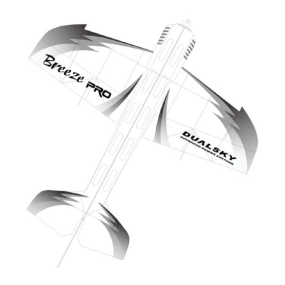
- Page 13 48. La partie indiquée peut être utilisé pour l'assemblage d’une tige en fibre de 1mm. La tige doit être acheté séparément. 49. As shown above, this is the completed Breeze PRO EVO. 49. Der fertige Breeze PRO EVO, wie in der obigen Abbildung zu sehen ist. 49. Le Breeze PRO EVO complété est indiqué ci-dessus.
Need help?
Do you have a question about the Breeze Pro Evo and is the answer not in the manual?
Questions and answers