
Related Manuals for Swagelok CWS-D100-1B

Summary of Contents for Swagelok CWS-D100-1B
- Page 1 E L D I N G Y S T E M ’ S E R A N U A L CWS-D100-1B CWS-D100-2B...
- Page 2 The Swagelok Limited Lifetime Warranty Swagelok hereby warrants to the purchaser of this Product that the non-electrical components of the Product shall be free from defects in material and workmanship for the life of the Product. All electrical components installed in or on the Product are warranted to be free from defects in material and workmanship for twelve months from the date of purchase.
-
Page 3: Table Of Contents
....Unpacking the Weld Head Cable Assembly and Related Components .... 2005 Swagelok Company, all rights reserved TOC−1 September 2005... - Page 4 ......3-33 Mating the Weld Head to the Fixture Block ..3-34 2005 Swagelok Company, all rights reserved TOC−2 September 2005...
- Page 5 ....Daily Maintenance ...... 2005 Swagelok Company, all rights reserved TOC−3 September 2005...
- Page 6 Electrode Geometry ...... 2005 Swagelok Company, all rights reserved TOC−4 September 2005...
- Page 7 ....Series 8 Micro Weld Head Fixture ... . Appendix I Weld Procedure Guidelines Index 2005 Swagelok Company, all rights reserved TOC−5 September 2005...
-
Page 8: September
CWS−D100−B Welding System Table of Contents 2005 Swagelok Company, all rights reserved TOC−6 September 2005... -
Page 9: Foreword
Your Swagelok representative can provide support and service of your Swagelok Welding System (SWS) as well as local stock of precision fittings and valves. Please take a moment to fill out the warranty information form as well as the information listed below. Keep this information available in case you need to contact your Swagelok representative. -
Page 10: Swagelok Company, All Rights Reserved
CWS−D100−B Welding System Foreword 2005 Swagelok Company, all rights reserved September 2005... -
Page 11: Safety Summary
This symbol identifies the location of all other types of warning or caution information which don’t have specific symbols. Accompanying text will identify the specific nature of the condition and if the condition is a warning or caution. 2005 Swagelok Company, all rights reserved September 2005... -
Page 12: Swagelok Company, All Rights Reserved September 2005
Do not use extension cords that are in poor physical condition or have insufficient current capacity. Failure to do so can pose fire and shock hazards. 2005 Swagelok Company, all rights reserved September 2005... - Page 13 1 WELDING HANDBOOK, VOLUME 2, 8TH EDITION, AMERICAN WELDING SOCIETY. Shut off shielding gas supply when not in use. 2005 Swagelok Company, all rights reserved September 2005...
- Page 14 Do not use welder to thaw frozen pipes. Do not use extension cords that are in poor physical condition or have insufficient current capacity. Failure to do so can pose fire and shock hazards. 2005 Swagelok Company, all rights reserved September 2005...
-
Page 15: Safe Practices And Safety Precautions
Keep protective cap in place over valve except when cylinder is in use or connected for use. Read and follow instructions on compressed gas cylinders, associated equipment, and CGA publication P−1 listed in Safety Standards. 2005 Swagelok Company, all rights reserved September 2005... - Page 16 OR IMPROPERLY TREATED. cause burns. MAGNETIC FIELDS can affect pacemakers. WARNING! Pacemaker wearers keep away. PACEMAKER WEARERS KEEP AWAY. Wearers should consult their doctor before going near welding operations. 2005 Swagelok Company, all rights reserved viii September 2005...
-
Page 17: User Precautions
USERS SHOULD NOT There are no user serviceable parts in the power SERVICE THE supply other than a fuse. Refer all other servicing POWER SUPPLY. to your Authorized Swagelok sales and service representative. 2005 Swagelok Company, all rights reserved September 2005... -
Page 18: Power Supply Warning Label
CWS−D100−B Welding System Foreword Power Supply Warning Label This warning label is affixed to the power supply. 2005 Swagelok Company, all rights reserved September 2005... -
Page 19: Referenced Specifications
Documents, P.O. Box 371954, Pittsburgh, PA 15250 (www.osha.gov). 5. OSHA 29CFR 1926 Subpart J, Welding and Cutting. Acquire from U.S. Government Printing Office, Superintendent of Documents, P.O. Box 371954, Pittsburgh, PA 15250 (www.osha.gov). 2005 Swagelok Company, all rights reserved September 2005... - Page 20 CWS−D100−B Welding System Foreword 2005 Swagelok Company, all rights reserved September 2005...
-
Page 21: Introduction Sws D100
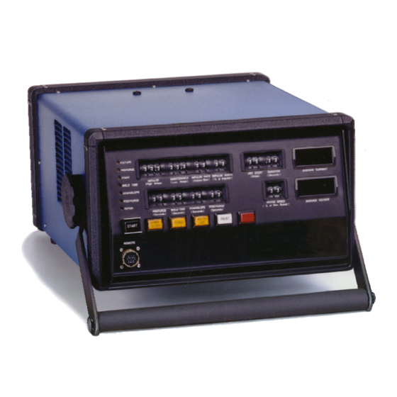
Section 1 Introduction SWS D100 The Swagelok Welding System (SWS) is a versatile, portable and easy to use orbital welding system. This section includes gas tungsten arc welding system components overview of SWS operation specifications. Figure 1-1 Swagelok Welding System ... -
Page 22: Gas Tungsten Arc Welding
2005 Swagelok Company, all rights reserved September 2005... -
Page 23: Process Variables
Increasing travel speed decreases the width of the weld. Travel speed generally is fixed in mechanized welding. Other variables such as current or voltage are varied to maintain control of the weld. 2005 Swagelok Company, all rights reserved September 2005... -
Page 24: System Components
Simplified controls and displays provide efficient programming and monitoring of the welding process. See Table 1-1 on page 1-9 for the power supply specifications. Figure 1-2 SWS D100 Power Supply 2005 Swagelok Company, all rights reserved September 2005... -
Page 25: The Weld Head
See Table 1-5 on page 1-10 for the weld head specifications. Series 20 Series 10 Series 5 Series Micro Motor Module Series Micro Motor Module Series 4 Micro Series 4 Micro (Rigid) (Flexible) Series 8 Micro Figure 1-3 Weld Heads 2005 Swagelok Company, all rights reserved September 2005... -
Page 26: Fixture Blocks
The collets exchange quickly, making the fixture block very adaptable to changing work requirements. Tables 1-6, 1-7, and 1-8 list the available fixtures and collets. Series 5 Series 20-A Series 20-B Series 10 Series 8 Series 4 Figure 1-4 Standard Fixtures 2005 Swagelok Company, all rights reserved September 2005... -
Page 27: Overview Of Sws Operation
The correct settings used for a specific job are developed into a weld procedure guideline. The guideline is used to maintain repeatability and quality control for subsequent jobs of the same type. 2005 Swagelok Company, all rights reserved September 2005... - Page 28 CWS−D100−B Welding System Introduction Figure 1-5 SWS D100 Front Panel Controls 2005 Swagelok Company, all rights reserved September 2005...
-
Page 29: Specifications
20 in. (51 cm) deep 9 in. (23 cm) high (without handle) CWS-D100-2B 15 1/2 in. (39 cm) wide 45 lbs (20.4 kg) 20 in. (51 cm) deep 9 in. (23 cm) high (without handle) 2005 Swagelok Company, all rights reserved September 2005... - Page 30 ** Designates size in 1/16ths or mm; 4MFA- includes sizes 01, 02, 04, 3 mm, and 6 mm. 8MF- includes sizes 04, 06, 08, 6 mm, 8 mm, 10 mm, and 12 mm 2005 Swagelok Company, all rights reserved 1-10 September 2005...
- Page 31 SWS-20FSP1L and SWS-20FSP1R add MM (MMTN) suffix for metric sizes SWS-20UCI-MC collet to hold ferrule mandrels for SWS-20TFB-A fixture block ** − Identifies the collet size in 1/16ths or metric (MM suffix) 2005 Swagelok Company, all rights reserved 1-11 September 2005...
- Page 32 CAN POSE FIRE AND Some power loss will occur, depending on the length of the extension SHOCK HAZARDS. cord. See Table 1-10 to determine the minimum wire size to use. 2005 Swagelok Company, all rights reserved 1-12 September 2005...
-
Page 33: Installation
Section 2 Installation Introduction This section describes the procedures necessary for installing the Swagelok Welding System (SWS). This section includes: tools and accessory requirements electrical requirements unpacking and inspecting system components installing the SWS installing the gas delivery system preliminary check. -
Page 34: Tools And Accessory Requirements
A two-stage gas regulator is suggested. The regulator should reduce the source pressure to 25 psig to 50 psig (1.9 bar to 3.5 bar) for the arc shielding and internal (backing) purge flow meters. 2005 Swagelok Company, All right reserved September 2005... -
Page 35: Electrical Requirements
If the length of the cord is greater than 100 ft, Note: The voltage drop in an call your Swagelok representative for extension cord 100 ft long may affect the output performance of recommended guidelines. the SWS. 2005 Swagelok Company, All rights reserved September 2005... -
Page 36: Unpacking And Inspecting System Components
5. Record the model and serial numbers, and the delivery dates on page i of the Forward section of this user’s manual. 2005 Swagelok Company, All right reserved September 2005... -
Page 37: Unpacking The Weld Head Cable Assembly
4. Verify that the weld head serial number matches the serial number on the shipping container. 5. Record the model and serial numbers, and the delivery dates on page i of the Forward section of this user’s manual. 2005 Swagelok Company, All rights reserved September 2005... -
Page 38: Installing The Sws
Do not connect the power cord to the outlet at this time. 5. Turn off the circuit breaker. Refer to Figure 2-3. Figure 2-3 Power Supply Circuit Breaker in the OFF Position 2005 Swagelok Company, All right reserved September 2005... -
Page 39: Installing The Weld Head
Connect the four connectors to the rear panel of the power supply by performing the following steps (see Figure 2-5): 1. Locate the weld head assembly. Figure 2-4 Weld Head Assembly Figure 2-5 Weld Head Connectors 2005 Swagelok Company, All rights reserved September 2005... - Page 40 . Ensure that the connector is firmly TO WELD HEAD Swagelok Quick-Connect attached. This connection provides shielding gas to the stem (SS-QC4-S-400). weld head through a solenoid valve in the power supply. 2005 Swagelok Company, All right reserved September 2005...
-
Page 41: Installing The Gas Delivery System
Gas Delivery System Refer to the installation procedure beginning on page 2-10. gas delivery system using a secondary shielding gas solenoid valve Refer to the installation procedure beginning on page 2-12. 2005 Swagelok Company, All rights reserved September 2005... -
Page 42: Installing The Typical Shielding/Purge Gas Delivery System
Adjust the low-pressure regulator gage to reduce the gas storage container source pressure to 25 psig to 50 psig. When complete, continue to the Preliminary Check procedure beginning on page 2-14. 2005 Swagelok Company, All right reserved 2-10 September 2005... - Page 43 Reducing Union with Nylon (Swagelok Union or Reducing Union Ferrules or Ultra-Torr with Nylon Ferrules or Ultra-Torr for Purge Gas Restriction) SWS Fixture Block Figure 2-6 Typical Gas Delivery System 2005 Swagelok Company, All rights reserved 2-11 September 2005...
-
Page 44: Installing The Optional Gas Delivery System
Ensure all connections are tight and do not leak. Observe correct polarity on the secondary solenoid bypass plug. Adjust the low pressure regulator gage to reduce the gas storage container source pressure to 25 psig to 50 psig. 2005 Swagelok Company, All right reserved 2-12 September 2005... - Page 45 Valve Internal Secondary Solenoid Purge Gas Bypass Plug Flow Meter Weld Head Internal Purge Gas Shut-Off Valve SWS Fixture Block Secondary Solenoid Bypass Plug Figure 2-7 Optional Gas Delivery System 2005 Swagelok Company, All rights reserved 2-13 September 2005...
-
Page 46: Preliminary Check
See Figure 2-9. If the power supply does not come on, refer to Section 7, Troubleshooting, for a list of possible causes and corrective actions. Figure 2-9 Weld Status Indicator Lights 2005 Swagelok Company, All right reserved 2-14 September 2005... - Page 47 6. Turn off the power supply. its home position before welding. If problems occur, refer to Section 7, Troubleshooting, for a list of possible causes and corrective actions. Figure 2-11 Checking the Rotor Rotation 2005 Swagelok Company, All rights reserved 2-15 September 2005...
- Page 48 CWS−D100−B Welding System Installation 2005 Swagelok Company, All right reserved 2-16 September 2005...
-
Page 49: Operation
Section 3 Operation Introduction This section describes the basic operation of the Swagelok Welding System (SWS). This section includes front panel controls SWS modes of operation installing the electrode in the Series 5/10/20 Weld Head setting the arc gap preparing the work... -
Page 50: Front Panel Controls
The status indicator lights on the front panel show the welding process sequence or flash a warning if the power supply detects that a weld parameter is set incorrectly. 2005 Swagelok Company, All rights reserved September 2005... -
Page 51: Current Control Switches
Impulse current level for each Impulse/Maintenance cycle. (Amps) sets the output current during the ARC START duration period. This current level helps stabilize the initiated arc develops the weld puddle. 2005 Swagelok Company, all rights reserved September 2005... -
Page 52: Timing Control Switches
During this time, the rotor continues to move at the speed specified by the rotor speed rotary switch. The downslope cycle reduces the chance of weld cracking. 2005 Swagelok Company, All rights reserved September 2005... - Page 53 Table 3-1 Maximum Rotor Speed by cable added. Weld Head Model Maximum Rotor Speed Seconds/ Weld Head Model (RPM) Revolution Micro Weld Head Series 5/10 Weld Head Series 20 Weld Head 2005 Swagelok Company, all rights reserved September 2005...
-
Page 54: Pushbuttons
The at the user’s option. pushbutton overrides the prepurge and postpurge timers See Section 2, Installation, for and allows shielding gas to continuously flow through installation information. the weld head. 2005 Swagelok Company, All rights reserved September 2005... - Page 55 PRINT weld data to the printer port on the rear of the unit. The optional CWS-DRP printer accepts the data and prints the record. Figure 3-5 Rotor Home Position 2005 Swagelok Company, all rights reserved September 2005...
-
Page 56: Status Indicator Lights
Caution! Rotor indicates the rotor is in motion. DO NOT try to remove the fixture block from the weld head until all status indicator lights are off. 2005 Swagelok Company, All rights reserved September 2005... -
Page 57: Digital Displays
Table 3-3 shows all the message codes used by the power supply. Note that certain code ranges are marked Factory Use. These codes, except for 64 to 96, are normally not used, which is noted in the table. 2005 Swagelok Company, all rights reserved September 2005... - Page 58 2 digit Program Programmable 00=2000 mode Date printing 0=mm/dd/yy Program Programmable format 1=dd/mm/yy mode 36 to 40 Factory use Not used Paper out No paper Caution installed with printer power on 2005 Swagelok Company, All rights reserved 3-10 September 2005...
- Page 59 Note (A): Press STOP/RESET to clear the error. Rotor will not move again unless STOP/RESET is pressed a second time. Note (B): Service may be necessary. Call your Swagelok representative. 2005 Swagelok Company, all rights reserved 3-11 September 2005...
-
Page 60: Operational Mode
Caution ≥ Rotor Speed 5 % to 99 % Caution 1 or < 5 < 1 Disable* The Prepurge, Start, Weld Time, Downslope, and Postpurge status indicator lights are flashing. 2005 Swagelok Company, All rights reserved 3-12 September 2005... - Page 61 Figure 3-9(A) shows the low limit for IMPULSE is 5. Figure 3-9(B) shows the high limit for WIDTH IMPULSE is 95. WIDTH 2005 Swagelok Company, all rights reserved 3-13 September 2005...
- Page 62 The sequence repeats continuously until the errors are cleared. If the message code is caused by a “disable” condition, the status indicator lights blink as the code is displayed. 2005 Swagelok Company, All rights reserved 3-14 September 2005...
- Page 63 The power supply monitors the rotor when a move command is given. If no motion is detected, the code is displayed, and the system is disabled. 2005 Swagelok Company, all rights reserved 3-15 September 2005...
- Page 64 When Prepurge is changed to one second or Figure 3-11 Display Readout for greater, the displays return to normal. Example 2 2005 Swagelok Company, All rights reserved 3-16 September 2005...
-
Page 65: Program Mode
Enter a number into the switch, and the code number is shown on the Average Voltage display. Figure 3-12 Entering Program Mode Data associated with the code number will be displayed on the Average Current display. 2005 Swagelok Company, all rights reserved 3-17 September 2005... - Page 66 1.5 seconds to be considered valid. The counter number will be printed on the weld data record. See the description of the optional printer in Appendix B, Optional Equipment. 2005 Swagelok Company, All rights reserved 3-18 September 2005...
- Page 67 The rotary switch settings may have ARC START DURATION to be increased when Arc Start power is set to zero. 2005 Swagelok Company, all rights reserved 3-19 September 2005...
- Page 68 Optional Equipment, for an example of the printout. After entry, press to start the print cycle. Average ROTOR JOG Voltage will show the number 42 while data is being sent to the printer. 2005 Swagelok Company, All rights reserved 3-20 September 2005...
- Page 69 For this example, 1 would be displayed first, followed by 000., to show the value of 1000. See Figure 3-14. Figure 3-14 Data Display for Values Above 999 2005 Swagelok Company, all rights reserved 3-21 September 2005...
-
Page 70: Test Mode
Code 98 is the front panel light test. Use this test to verify all front panel status indicator lights and LED displays. 2005 Swagelok Company, All rights reserved 3-22 September 2005... - Page 71 0, the unit displays the values in switch Figure 3-16 LED Test Display IMPULSE two, . Use the same method described earlier MAINTENANCE to verify the operation of this switch. 2005 Swagelok Company, all rights reserved 3-23 September 2005...
- Page 72 The order is established by the button positions on the power supply front panel. See Table 3-7 for all pushbutton/indicator light pairings. 2005 Swagelok Company, All rights reserved 3-24 September 2005...
- Page 73 1. To return to the program mode, press DOWNSLOPE simultaneously. STOP/RESET After releasing the pushbuttons, the system will return to program mode. 2. Press to exit program mode and return to STOP/RESET operational mode. 2005 Swagelok Company, all rights reserved 3-25 September 2005...
-
Page 74: Installing The Electrode In The Series 5/10/20 Weld Head
Operation Installing the Electrode in the Series 5/10/20 Weld Head Each Swagelok weld head comes with a selection of electrodes. The following instructions show how to properly install the electrode in the Series 5/10/20 weld head. See Section 4, Micro Weld Head, for the micro weld head instructions. -
Page 75: Setting The Arc Gap
4. To calculate arc gap gage settings for other arc gaps, see the arc gap gage setting formula in Appendix E, Arc Gap Gage Setting Tables. 5. Gage settings for Swagelok ATW fittings are in the tables in Appendix E, Arc Gap Gage Setting Tables. Setting the Arc Gap 1. -
Page 76: Preparing The Work
Deburr the ends, making sure that both the inside and outside diameters are square and burr-free. Clean the tube ends using an appropriate solvent. 2005 Swagelok Company, All rights reserved 3-28 September 2005... -
Page 77: Fixturing The Work
Make sure the Fixture Side Plate collet shoulder is flush against the fixture side plate. See Figure 3-22. Collet Shoulder Figure 3-22 Installing Collets 2005 Swagelok Company, all rights reserved 3-29 September 2005... -
Page 78: Aligning The Work Pieces In The Tube Fixture Block
Figure 3-23 Place the Centering Gage Note: When welding a Swagelok ATW fitting to tubing, butt the tubing against the centering gage first. Figure 3-24 Placing First Work Piece in the Fixture Block 2005 Swagelok Company, All rights reserved 3-30 September 2005... - Page 79 6. Inspect 360° around the weld joint for fit and alignment. If the alignment is not correct, proceed to the Appendix H, Fixture Block Alignment. Figure 3-25 Placing Second Work Piece 2005 Swagelok Company, all rights reserved 3-31 September 2005...
-
Page 80: Connecting The Purge Gas Line
2. Open the shut-off valve in the purge gas line. The length of time for internal purge before welding depends on the internal volume and length of the work piece to be welded. 2005 Swagelok Company, All rights reserved 3-32 September 2005... -
Page 81: Connecting The Weld Head To The Fixture Block
Model No. Serial No. CWS-M-MTR-A 10212 or higher CWS-4MRH-A 20090 or higher CWS-4MFH-A 30045 or higher CWS-8MRH CWS-5H-B 60100 or higher CWS-10H-A 70033 or higher CWS-20H-A 80015 or higher SWS-20H-B 2005 Swagelok Company, all rights reserved 3-33 September 2005... -
Page 82: Mating The Weld Head To The Fixture Block
See Figure 3-27(B). 4. Examine the Fixture light. Verify that it is off. Figure 3-26 Releasing the Locking Lever Figure 3-27 Mating the Weld Head to the Fixture Block 2005 Swagelok Company, All rights reserved 3-34 September 2005... -
Page 83: Using A Weld Procedure Guideline
Appendix I, Weld Procedure Guidelines, of this manual. If assistance is needed in obtaining more Weld Procedure Guidelines, please provide your Swagelok representative with your specific requirements. The weld procedure guideline listed in Table 3-9 is based on 1/2 in. -
Page 84: Effects Of Weld Parameters
Impulse Width also affects weld penetration. The control allows fine tuning of the weld penetration level. Pulse rate is typically set so that each weld spot overlaps the previous one by at least 60 %. 2005 Swagelok Company, All rights reserved 3-36 September 2005... -
Page 85: Setting The Shield Gas Flow
The weld head is connected to the fixture block. The proper weld procedure guideline settings have been entered. All status indicator lights are off. The internal purge gas is flowing. 2005 Swagelok Company, all rights reserved 3-37 September 2005... -
Page 86: Display Indications During Welding
Arc Start on the weld procedure guideline. The Arc Start value is calculated during the development of the guideline. The value displayed during welding is generally within 10 % of the calculated value. 2005 Swagelok Company, All rights reserved 3-38 September 2005... -
Page 87: After The Weld Is Complete
7. Open the side plates of the fixture block. Note: Inspect and clean the electrode after each weld. Look for 8. Remove the welded assembly. oxidation, wear, or weld material on the tip. 2005 Swagelok Company, all rights reserved 3-39 September 2005... -
Page 88: Operation Summary
11. Program the welder. 12. Press and complete the weld. START 13. Remove the weld head from the tube fixture block. 14. Remove the welded assembly from the tube fixture block. 2005 Swagelok Company, All rights reserved 3-40 September 2005... -
Page 89: Micro Weld Heads Cws-4Mrh-A, Cws-4Mfh-A, Cws-8Mrh
All micro weld heads operate with a detachable motor module. See Figure 4-1. Series 4 Series 8 Flexible-Drive Rigid-Drive Motor Module Series 4 Rigid-Drive Figure 4-1 Rigid-Drive and Flexible-Drive Micro Weld Heads 2005 Swagelok Company, All rights reserved September 2005... - Page 90 2005 Swagelok Company, All rights reserved September 2005...
-
Page 91: Using The Micro Fixture Tool
2-7 in Section 2, Installation, for instructions. 3. Turn on the power supply. 4. Press STOP/RESET The motor moves the rotor drive gear to its home position. Figure 4-3 Power Supply Circuit Breaker 2005 Swagelok Company, All rights reserved September 2005... -
Page 92: Installing The Micro Weld Head
Figure 4-4 Rotor Manual Adjustment 3. Align the connecting surfaces of the micro weld head and motor module. See Figure 4-5. O-ring Valve Mating Connections Figure 4-5 O-ring and Mating Connections 2005 Swagelok Company, All rights reserved September 2005... - Page 93 Refer to step 1. on page 4-4. Figure 4-6 Connecting Weld Head and Motor Module 2005 Swagelok Company, All rights reserved September 2005...
-
Page 94: Installing/Replacing The Electrode
See Figure 4-7. Electrode Clamping Screw Figure 4-7 Electrode Clamping Screw Location Caution! Do not rotate the rotor with the electrode clamping screw loose. Damage to the micro weld head housing may result. 2005 Swagelok Company, All rights reserved September 2005... - Page 95 Push the electrode into the electrode cleaning tool and rotate back and forth two to three times. Figure 4-8 Installing the Electrode 2005 Swagelok Company, All rights reserved September 2005...
-
Page 96: Setting The Arc Gap
The 9. Turn on the power supply. electrode could be damaged as a result. 10. Press STOP/RESET The rotor starts moving and stops at the home position. 2005 Swagelok Company, All rights reserved September 2005... -
Page 97: Fixturing The Work
Series 4 and Series 8 fixtures. Figure 4-11 Inserting Centering Gage Note: Use the micro fixture tool for Opening the Fixture Series 4 and Series 8 fixtures Figure 4-12 Insert First Work Piece 2005 Swagelok Company, All rights reserved September 2005... - Page 98 See Appendix G, Gas Flow Rate Tables. Correct Wrong Figure 4-14 Proper Latch Position (Series 8 Fixture) 2005 Swagelok Company, All rights reserved 4-10 September 2005...
-
Page 99: Connecting The Micro Weld Head To The Fixture
3. Program the power supply and perform the weld using the procedures established in Section 3, Operation. 2005 Swagelok Company, All rights reserved 4-11 September 2005... - Page 100 CWS−D100−B Welding System Micro Weld Heads Latch Spring Captures Button Keepers Locking Latch Springs (2) Lever Figure 4-15 Placing the Fixture on the Micro Weld Head 2005 Swagelok Company, All rights reserved 4-12 September 2005...
-
Page 101: Considerations During Welding
CWS−D100−B Welding System Considerations During Welding The approach to welding using the micro weld head is similar to that used for other Swagelok weld heads. Develop Hold Here a weld procedure guideline as you would for any job. The power supply controls and indicators work the same. -
Page 102: Using The Optional Bench Mounting Bracket
Fasten the latch to secure the micro weld head to the bracket. Figure 4-17 Using the Series 4 Mount Bracket 2005 Swagelok Company, All rights reserved 4-14 September 2005... -
Page 103: Series 8 Bench Mount Bracket
5. Position the weld head so that the exposed ends of the adapter screws slide through the holes in the bracket. See Figure 4-18(C). Figure 4-18 Using the Series 8 Bench Mount Bracket 2005 Swagelok Company, All rights reserved 4-15 September 2005... - Page 104 Keep the thumb nuts on the adapter screws when not using the bench mount bracket. See Figure 4-19. Figure 4-19 Storing the Thumb Nuts on the Adapter Screws 2005 Swagelok Company, All rights reserved 4-16 September 2005...
-
Page 105: Weld Parameter Adjustment
The example in the following procedure is based on 1/2 in. OD, 0.049 in. wall thickness 316L stainless steel tubing using the Series 5 Weld Head. The procedure applies for all weld heads. 2005 Swagelok Company, all rights reserved September 2005... -
Page 106: Determining The Work Specifications
0.035 in. The proper arc gap arc gap (0.907 in.) in the arc gap gage with either a gage setting depends on the weld caliper or micrometer. head model and the outside diameter of the components. Swagelok Company, All rights reserved September 2005... -
Page 107: Setting The Front Panel Switches
For according to the result (26) e. Set ROTOR SPEED example, 25 is 25 % of the in step 2.d. maximum speed of the CWS-5H-B weld head. 2005 Swagelok Company, all rights reserved September 2005... - Page 108 Table 5-4 Wall Thickness and “B” Factor Wall Thickness Range “B” Factor 0.015 to 0.045 0,381 to 1,143 0.25 0.046 to 0.083 1,168 to 2,108 0.30 0.084 to 0.109 2,133 to 2,769 0.40 Swagelok Company, All rights reserved September 2005...
- Page 109 2,133 to 2,769 Refer to “Identifying Proper Welds” on page 5-17 to see the effect of b. Set (35) according to Table 5-5. IMPULSE WIDTH the Impulse Rate on the weld. 2005 Swagelok Company, all rights reserved September 2005...
- Page 110 PURGE times may be necessary for certain applications. When using a weld head extension cable, increase the Prepurge time one second for each foot of extension length. Swagelok Company, All rights reserved September 2005...
- Page 111 38 for a two-pass weld based upon the following criteria: : 25 ROTOR SPEED Seconds per revolution: 19 Seconds per revolution for a single-pass weld: 19 Seconds per revolution for a two-pass weld: 19 × 2 = 38 2005 Swagelok Company, all rights reserved September 2005...
- Page 112 Postpurge time is 20 seconds. This time allows for sufficient cooling of the electrode and weld zone. Additional Postpurge time may be necessary for a weld made with a high average current setting. Swagelok Company, All rights reserved September 2005...
-
Page 113: Example Weld Procedure Guideline Worksheet
19 × 2= 38 If tube outside dia > 1/2 in.: s/rev. • = WELD TIME 19 s DOWNSLOPE Weld Time × 0.5 = DOWNSLOPE 38 × 0.5 = 19 20 s POSTPURGE 2005 Swagelok Company, all rights reserved September 2005... -
Page 114: Weld Procedure Guideline Worksheet
= WELD TIME ________ × 2= If tube outside dia > 1/2 in.: s/rev. • = WELD TIME ________ = DOWNSLOPE Weld Time × 0.5 = DOWNSLOPE ________ × 0.5 = POSTPURGE Swagelok Company, All rights reserved 5-10 September 2005... - Page 115 20 19 18 17 16 15 14 13 12 11 10 9 8 7 6 5 4 3 2 1 Travel Speed (in./min) Seconds per Revolution SERIES 5 WELD HEAD − TUBE WELDING Figure 5-1 Rotor Switch Speed Setting Graphs (Micro Weld Head, Series 5 Weld Head)− Fractional 2005 Swagelok Company, all rights reserved 5-11 September 2005...
- Page 116 2 in. Travel Speed (in./min) Seconds per Revolution SERIES 20 WELD HEAD − TUBE WELDING Figure 5-2 Rotor Switch Speed Setting Graphs (Series 10 Weld Head, Series 20 Weld Head)− Fractional Swagelok Company, All rights reserved 5-12 September 2005...
- Page 117 20 19 18 17 16 15 14 13 12 11 10 9 8 7 6 5 4 3 2 Travel Speed (in./min) Seconds per Revolution SERIES 20 WELD HEAD − PIPE WELDING Figure 5-3 Rotor Switch Speed Setting Graphs (Series 20 Weld Head)− Fractional 2005 Swagelok Company, all rights reserved 5-13 September 2005...
- Page 118 Model CWS-D100-1B CWS-D100-2B Travel Speed (mm/s) Seconds per Revolution SERIES 5 WELD HEAD − TUBE WELDING Figure 5-4 Rotor Switch Speed Setting Graphs (Micro Weld Head, Series 5 Weld Head)− Metric Swagelok Company, All rights reserved 5-14 September 2005...
- Page 119 Travel Speed (mm/s) Seconds per Revolution SERIES 20 WELD HEAD − TUBE WELDING Figure 5-5 Rotor Switch Speed Setting Graphs (Series 10 Weld Head, Series 20 Weld Head) − Metric 2005 Swagelok Company, all rights reserved 5-15 September 2005...
-
Page 120: Evaluating The Weld
Identifying Typical Weld Discontinuities Figure 5-7 shows typical weld discontinuities. TYPICAL WELD DISCONTINUITIES Incomplete Penetration Partial Penetration Concavity Excessive Drop Through Weld Pool Shift Axial Misalignment Angular Misalignment Figure 5-7 Typical Weld Discontinuities Swagelok Company, All rights reserved 5-16 September 2005... -
Page 121: Identifying Proper Welds
ID Weld Bead Arc Gap 0.035 in. Figure 5-8 Reference Weld Illustration Avg. Current Display (Amperes) The following examples show how changes in various parameters can affect the weld shape. 2005 Swagelok Company, all rights reserved 5-17 September 2005... - Page 122 Raising the Impulse current raises the average current. This increases the heat input per unit of electrode travel resulting in increased inside diameter dropthrough and weld bead width. Reference Weld Illustration Swagelok Company, All rights reserved 5-18 September 2005...
- Page 123 Raising the Maintenance current raises the average current. This increases the heat input per unit of electrode travel resulting in increased inside diameter dropthrough and weld bead width. Reference Weld Illustration 2005 Swagelok Company, all rights reserved 5-19 September 2005...
- Page 124 Lengthening the Impulse Width raises the average current. This increases the heat input per unit of electrode travel resulting in increased inside diameter dropthrough and weld bead width. Reference Weld Illustration Swagelok Company, All rights reserved 5-20 September 2005...
- Page 125 26 (19) 19 (26) Lowering the Rotor Speed increases the heat input per unit of electrode travel resulting in increased inside diameter dropthrough and weld bead width. Reference Weld Illustration 2005 Swagelok Company, all rights reserved 5-21 September 2005...
-
Page 126: Adjusting Controls For Weld Quality
At times, the welding parameters (as described on page 5-9) must be adjusted to create an acceptable weld. Use the flow chart in Figure 5-20 to assist in adjusting the weld parameters. Swagelok Company, All rights reserved 5-22 September 2005... - Page 127 RE-EVALUATE INCREASE THE The weld may also have ORIGINAL WELD TRAVEL SPEED PROCEDURE (IN./MIN) to meet additional GUIDELINE cleanliness requirements. Figure 5-20 Weld Procedure Guideline Flowchart 2005 Swagelok Company, all rights reserved 5-23 September 2005...
- Page 128 CWS−D100−B Welding System Weld Parameter Adjustment Swagelok Company, All rights reserved 5-24 September 2005...
-
Page 129: Maintenance
Section 6 Maintenance Introduction To ensure your Swagelok Welding System (SWS) Note: If you experience problems equipment is always in proper working order, you must while performing the procedures in this section, refer to Section 7, perform periodic maintenance on the system components. -
Page 130: Series 5/10/20 Fixture Blocks
See Figure 6-1(C). Remove heavier deposits with a fine-grit abrasive pad. 4. Check the lever cam and latch for smooth operation. See Figure 6-2. Figure 6-2 Lever Cam and Latch 2005‘ Swagelok Company, all rights reserved September 2005... -
Page 131: Micro Weld Head Fixture Blocks
Figure 6-4. d. Wrap the tape tightly (approximately 1 1/2 turns). The tape should end at the outside edge of the top surface. Figure 6-4 Checking/replacing the Insulator Tape 2005 Swagelok Company, all rights reserved September 2005... -
Page 132: Series 5/10/20 Weld Head
38 for a Series 20 Weld Head the weld head. This sets a rotor speed of 13 seconds per revolution for the micro weld head and 26 seconds per revolution for the Series 5/10/20 Weld Head. 2005‘ Swagelok Company, all rights reserved September 2005... -
Page 133: Series 5/10/20 Weld Head Disassembly And Cleaning
3. Remove the work extension screw with lock washer, and the work extension. Inspect the work extension for pitting, wear, or damage. See Figure 6-7. Figure 6-7 Removing the Work Extension 2005 Swagelok Company, all rights reserved September 2005... - Page 134 See Figure 6-10. Figure 6-8 Removing the Locking Ring Half of the Weld Head Housing Rotor Figure 6-9 Removing the Rotor Power Block Subassembly Figure 6-10 Removing the Power Block Subassembly 2005‘ Swagelok Company, all rights reserved September 2005...
- Page 135 Appendix F, Part Drawings. Power Strap Screws Figure 6-12 Inspecting the Power Strap Screws Screw Work Plate Figure 6-13 Inspecting the Work Plate and Screws 2005 Swagelok Company, all rights reserved September 2005...
- Page 136 Dry the balls thoroughly. Rings Gear Ring Ball Bearing Brush Ring Figure 6-16 Separating the Gear Ring from the Brush Ring Caution! Do not use a flammable liquid to clean the ball bearings. 2005‘ Swagelok Company, all rights reserved September 2005...
-
Page 137: Series 5/10/20 Weld Head Assembly
2. Complete the steps in reverse order in the weld head disassembly procedure on page 6-5. Caution! Do not pinch any internal wiring or damage the safety interlock sensor during reassembly. 2005 Swagelok Company, all rights reserved September 2005... -
Page 138: Micro Weld Heads
See Figure 6-19. 2. Store the micro weld head in a clean, dry place. Figure 6-19 Inspect Exposed Surfaces of the Weld Head 2005‘ Swagelok Company, all rights reserved 6-10 September 2005... -
Page 139: Eight-Hour Maintenance
4. Clean the two power lugs on the weld head with the provided stainless steel wire brush. See Figure 6-21. Figure 6-20 Cleaning the Power Lug Sockets and the Purge Port Power Lugs Figure 6-21 Cleaning the Weld Head Power Lugs 2005 Swagelok Company, all rights reserved 6-11 September 2005... - Page 140 13. Inspect all other weld head components and clean any that are dirty. Blow any loose dirt from the weld head Figure 6-23 Lifting the Weld Head with clean, dry, low-pressure air. Brush for Cleaning 2005‘ Swagelok Company, all rights reserved 6-12 September 2005...
- Page 141 Replace if necessary. See Figure 6-25(D). 10. Clean the idler gears with a solvent and a soft cloth. Body Brush Side Figure 6-25 Removing Series 8 Micro Weld Head Components for Cleaning 2005 Swagelok Company, all rights reserved 6-13 September 2005...
- Page 142 Blow any loose dirt from the weld head with clean, dry, low-pressure air. Correct Position Incorrect Position (Spring Covered by Brush) (Spring Exposed Under Brush) Figure 6-27 Spring Position 2005‘ Swagelok Company, all rights reserved 6-14 September 2005...
-
Page 143: Micro Weld Head Assembly
A blown fuse does not permit an arc to start. To inspect the fuse: 1. Turn off the power supply. See Figure 6-28. 2. Unplug the power cord. Figure 6-28 Power Supply Circuit Breaker in the OFF position 2005 Swagelok Company, all rights reserved 6-15 September 2005... - Page 144 Use only insulated pliers to fuse. If it is blown, replace it with a fuse of the remove fuse. same type and rating. 4. Turn on the power supply. Figure 6-29 Ceramic Fuse Location 2005‘ Swagelok Company, all rights reserved 6-16 September 2005...
-
Page 145: Troubleshooting
Be prepared to give the following information to the Swagelok representative: the serial number and model number of the equipment involved complete description of the application the product is being used in detailed description of the symptom 2005 Swagelok Company, all rights reserved September 2005... -
Page 146: Repair/Replacement Instructions
The result is faster repair times and more assurance that the repair meets with your approval. Make the Swagelok representative aware if backup equipment is needed to temporarily replace the equipment being returned for repair. - Page 147 Dirty Use test mode Pushbutton does electrical contacts described in not function. Section 3, Operation, to verify switch operation. Call for service if the pushbutton switch is faulty. Switch failure 2005 Swagelok Company, all rights reserved September 2005...
- Page 148 The rear panel fixture Check that the fixture connector is not connector is seated Locking fully engaged. and its collar is tight. Ring Tab Figure 7-1 Fixture Block Locking Ring Tab 2005 Swagelok Company, all rights reserved September 2005...
- Page 149 Appendix F. Brush spring is Install the brush spring in installed incorrectly the correct orientation. See in micro weld head. Section 6, Maintenance. Bent motor shaft. Call for service. 2005 Swagelok Company, all rights reserved September 2005...
- Page 150 Weld head Check for damage and was dropped replace parts as necessary. Check rotor for smooth operation. Call for service if damage is severe. 2005 Swagelok Company, all rights reserved September 2005...
- Page 151 Incorrect arc Check the length of gap setting. the electrode and replace it. Reset arc gap. Melted electrode. No shielding gas. Check for shielding gas flow and set the proper flow rate. 2005 Swagelok Company, all rights reserved September 2005...
- Page 152 The weld head is Reassemble using the incorrectly assembled. instructions found in Section 6, Maintenance. Arc damage on fixture. Clean fixture. Remove and replace any damaged parts. 2005 Swagelok Company, all rights reserved September 2005...
-
Page 153: Welding Process
Inspect and clean all between tubing, contact surfaces. collet, and fixture block. Arc start power set Set Arc Start power to zero. (menu item 23) to one. See page 3-19 for details. 2005 Swagelok Company, all rights reserved September 2005... - Page 154 Contaminants in the Increase prepurge time. weld head and Check the gas source purge lines. for low pressure. Shielding gas line Reconnect gas line. disconnected from the power supply. 2005 Swagelok Company, all rights reserved 7-10 September 2005...
- Page 155 Loss of shield Check the shielding gas flow. gas source for low pressure. Check gas lines for leaks. Change to a different gas source or change oxygen removal filter. 2005 Swagelok Company, all rights reserved 7-11 September 2005...
- Page 156 Figure 5-17. Adjust weld parameters as necessary. Insufficient inside Compare flowmeter diameter purge settings to the weld gas flow. procedure guideline being used. Adjust if necessary. 2005 Swagelok Company, all rights reserved 7-12 September 2005...
- Page 157 The electrode is bent Inspect the electrode or was not and replace if properly installed. necessary. Reset the arc gap with the arc gap gage. 2005 Swagelok Company, all rights reserved 7-13 September 2005...
- Page 158 CWS−D100−B Welding System Troubleshooting 2005 Swagelok Company, all rights reserved 7-14 September 2005...
-
Page 159: Appendix A Glossary
The only control of this period is with arc start power, Code 23 in program mode. Arc Welding A type of welding process that uses an electrical arc as a source of heat to melt and join metals. 2005 Swagelok Company, all rights reserved September 2005... - Page 160 A weld joint where two work pieces are welded together with their long axes concentric and in-line. The joint can have various configurations, such as square groove, v-groove, j-groove, double v-groove, etc. 2005 Swagelok Company, all rights reserved September 2005...
- Page 161 Diagnostics A built-in program that checks the function of the front panel controls and indicators of the SWS power supply. Errors are shown on the front panel digital displays. 2005 Swagelok Company, all rights reserved September 2005...
- Page 162 GTAW process. GTAW An acronym for gas tungsten arc welding, the process used in the Swagelok Welding System (SWS). 2005 Swagelok Company, all rights reserved September 2005...
- Page 163 Multiple Pass A welding technique in which the rotor moves more than one revolution during the weld time. The technique is most helpful when fusion welding small diameter parts. 2005 Swagelok Company, all rights reserved September 2005...
- Page 164 Pulse Rate The rate at which the output current level is changed between the high (Impulse) and low (Maintenance) settings. The rate is expressed as pulses per second. 2005 Swagelok Company, all rights reserved September 2005...
- Page 165 Shielding Gas The gas used to shield the tungsten electrode and work pieces during the welding cycle. It also cools the weld head. 2005 Swagelok Company, all rights reserved September 2005...
- Page 166 An acronym used for universal collet insert, the exchangeable component used in the fixture block to hold the work pieces. The patented design inserts come in various sizes to match the outside diameter of the work pieces. 2005 Swagelok Company, all rights reserved September 2005...
- Page 167 Weld Time The portion of the weld cycle in which the current is at the level needed to fully penetrate the weld joint. The current will pulse between Impulse and Maintenance levels. 2005 Swagelok Company, all rights reserved September 2005...
- Page 168 CWS−D100−B Welding System Glossary 2005 Swagelok Company, all rights reserved A-10 September 2005...
-
Page 169: Appendix B Optional Equipment
Appendix B Optional Equipment This appendix lists the optional equipment available for your Swagelok Welding System (SWS). Contact your Swagelok representative for additional information on any listed option. This section includes: SWS Remote Pendant weld head extension cables data logging/monitoring SWS Data Recording Printer. -
Page 170: Sws Remote Pendant
The unit is attached to the power supply via the connector labeled on the front panel. See Figure B-2. Remote Figure B-1 Remote Pendant Remote Pendant Connector Figure B-2 Remote Pendant Connector 2005 Swagelok Company, all rights reserved September 2005... -
Page 171: Weld Head Extension Cables
Allow the shielding gas to flow for at least 60 seconds to clear the gas lines of oxygen. Press again to stop the gas flow. PURGE Figure B-3 Pushbutton Locations 2005 Swagelok Company, all rights reserved September 2005... -
Page 172: Data Logging/Monitoring
Visual, mechanical, and other testing must also be done to this feature. verify the weld integrity. As with any connection, proper leak testing should be performed once the weld is completed. 2005 Swagelok Company, all rights reserved September 2005... - Page 173 The data can be recalled as needed and can be used for later analysis of the welding process. Remember that data recording is just a method used to monitor the welding process and does not guarantee the quality of the weld. 2005 Swagelok Company, all rights reserved September 2005...
-
Page 174: Data Recording Printer
Install the printer using the instructions provided in section on paper loading.) this section. Ensure that the printer mechanism and paper path are clear of any packing materials or foreign matter. 2005 Swagelok Company, all rights reserved September 2005... - Page 175 7. Connect the printer cable to the connector on the rear of the printer. See Cabling the Printer on page B-9. 8. Run the self test described on page B-10 to ensure the paper is installed correctly. 2005 Swagelok Company, all rights reserved September 2005...
- Page 176 Insert and tighten the two black knobs to secure the printer. Figure B-9 Separating the Printer from the Mounting Bracket Figure B-10 Mount the Bracket to the Power Supply 2005 Swagelok Company, all rights reserved September 2005...
-
Page 177: Operating The Printer
SWITCH Down position power off Middle position power on Top position paper advance (spring loaded, momentary) LATCH Locks the printer inside the case. Latch Switch Figure B-12 Printer Front Panel Controls 2005 Swagelok Company, all rights reserved September 2005... - Page 178 Note: See page 3-17 for descriptions of the program mode paper be used. (Swagelok part number CWS-DRP-PAPER) items referenced in this section. Using the Printer Activate the printer from the power supply by one of...
- Page 179 50.2 10.0 TRAVEL DOWNSLOPE CURRENT VOLTAGE SPEED PERFORMANCE CONFIRMATION WELD NOT COMPLETE WELD HEAD ROTOR STALLED PERFORMANCE NOT ACCEPTABLE WELD ID# JOB IDENT OPERATOR IDENT Figure B-14 Weld No. 27 2005 Swagelok Company, all rights reserved B-11 September 2005...
-
Page 180: Weld Time
VOLTAGE SPEED 50.2 10.1 TRAVEL DOWNSLOPE CURRENT VOLTAGE SPEED PERFORMANCE CONFIRMATION WELD NOT COMPLETE ARC FAILURE PERFORMANCE NOT ACCEPTABLE WELD ID# JOB IDENT OPERATOR IDENT Figure B-16 Weld No. 29 2005 Swagelok Company, all rights reserved B-12 September 2005... - Page 181 SPEED 50.3 50.3 TRAVEL DOWNSLOPE CURRENT VOLTAGE SPEED PERFORMANCE CONFIRMATION WELD NOT COMPLETE STOP/RESET PUSHBUTTON PRESSED PERFORMANCE NOT ACCEPTABLE WELD ID# JOB IDENT OPERATOR IDENT Figure B-18 Weld No. 301 2005 Swagelok Company, all rights reserved B-13 September 2005...
- Page 182 Operation, for user instructions for the program mode. 23: Arc Start Power (0) 35: Date format: DD?MM?YY (1) 60: Non-resettable weld count: 1217 61: Non-resettable arc starts: 1239 Configuration dipswitch: 00 Figure B-19 User Parameter Printout 2005 Swagelok Company, all rights reserved B-14 September 2005...
-
Page 183: Maintenance
Figure B-21 Clearing a Paper Jam installed correctly. Cleaning The exterior SWS printer cabinet may be cleaned with a non-abrasive cleaner. Take care to prevent liquids from entering the mechanical assembly. 2005 Swagelok Company, all rights reserved B-15 September 2005... -
Page 184: Using A Standard Rs-232 Printer
Signal Name from SWS D100 Transmit Receive Clear to send (CTS) Signal ground +15 V (dc)** Data Transmit Ready (DTR) Ground ** Power to CWS-DRP. Do not wire to standard printer. 2005 Swagelok Company, all rights reserved B-16 September 2005... -
Page 185: Appendix C Electrode Selection Tables And Geometry
0.040 in. 10 mm (8,26 mm) (1,02 mm) CWS-C.040-.281-P 1/2 in. 0.281 in. 0.040 in. 12 mm (7,14 mm) (1,02 mm) *1/2 in., 12 mm ATW fittings are outside the usable range 2005 Swagelok Company, all rights reserved September 2005... -
Page 186: Cws-5H-B Weld Head
10 mm 12 mm 14 mm 15 mm 3/4 in. 0.855 in. 0.062 in. CWS-C.062-.855-P 7/8 in. (21,72 mm) (1,57 mm) 18 mm 22 mm 1 in. 23 mm 25 mm 2005 Swagelok Company, all rights reserved September 2005... -
Page 187: Cws-20H-A/B Weld Head
This illustration shows the electrode shape Swagelok suggests. Properly ground electrodes provide consistent, repeatable welds. Pre-ground electrodes are available from your Swagelok representative. See your parts list for ordering information. The electrode part numbers are assigned as follows: CWS − X.### − #.### − P... - Page 188 CWS−D100−B Welding System Electrode Selection Tables and Geometry 2005 Swagelok Company, all rights reserved September 2005...
- Page 189 0.035 in. (0,89 mm) or less. When welding 1/2 in. or 12 mm OD with a Series 8 weld head, use the single pass (one revolution) weld procedure only. 2005 Swagelok Company., all rights reserved September 2005...
-
Page 190: Appendix D Weld Head Information
20 19 18 17 16 15 14 13 12 11 10 9 8 7 6 5 4 3 2 1 Travel Speed (in./min) Seconds per Revolution SERIES 5 WELD HEAD − TUBE WELDING 2005 Swagelok Company, all rights reserved September 2005... -
Page 191: Series 10 Weld Head − Tube Welding
7/8 in. 3/4 in. 5/8 in. 1/2 in. 1 in. 1 1/4 in. Curve Model CWS-D100-1B 1 1/2 in. CWS-D100-2B 1 3/4 in. 2 in. Travel Speed (in./min) Seconds per Revolution SERIES 20 WELD HEAD − TUBE WELDING 2005 Swagelok Company., all rights reserved September 2005... -
Page 192: Series 20 Weld Head − Pipe Welding
12 mm 8.5 8.0 7.5 7.0 6.5 6.0 5.5 5.0 4.5 4.0 3.5 3.0 2.5 2.0 1.5 1.0 0.5 Travel Speed (mm/s) Seconds per Revolution MICRO WELD HEAD − TUBE WELDING 2005 Swagelok Company, all rights reserved September 2005... -
Page 193: Series 5 Weld Head − Tube Welding
12 mm 14 mm Curve Model 16 mm CWS-D100-1B CWS-D100-2B 18 mm 20 mm 22 mm 25 mm Seconds per Revolution Travel Speed (mm/s) SERIES 10 WELD HEAD − TUBE WELDING 2005 Swagelok Company., all rights reserved September 2005... -
Page 194: Series 20 Weld Head − Tube Welding
25 mm 20 mm 16 mm 28 mm Curve Model 35 mm CWS-D100-1B CWS-D100-2B 40 mm 52 mm Travel Speed (mm/s) Seconds per Revolution SERIES 20 WELD HEAD − TUBE WELDING 2005 Swagelok Company, all rights reserved September 2005... - Page 195 0,89 (see Table 5-3 on page 5-4). 0.056 to 0.064 1,41 to 1,63 0.040 1,02 0.065 to 0.082 1,64 to 2,28 0.045 1,14 0.083 to 0.154 2,29 to 4,00 0.050 1,39 2005 Swagelok Company, all rights reserved September 2005...
-
Page 196: Appendix E Arc Gap Gage Setting Tables
9,91 10,04 10,16 3,05 9,93 10,06 10,18 3,12 9,97 10,10 10,22 5,87 11,34 11,47 11,59 5,94 11,38 11,51 11,63 6,00 11,41 11,54 11,66 6,05 11,43 11,56 11,68 6,12 11,47 11,60 11,72 2005 Swagelok Company, all rights reserved September 2005... -
Page 197: Arc Gap Gage Setting Tables
17,15 17,28 17,41 17,53 0.500 0.677 0.682 0.687 0.692 17,20 17,33 17,46 17,58 0.503 0.678 0.683 0.688 0.693 17,22 17,35 17,48 17,60 0.505 0.679 0.684 0.689 0.694 17,25 17,38 17,51 17,63 2005 Swagelok Company, all rights reserved September 2005... - Page 198 17,60 10,14 17,25 17,38 17,50 17,63 11,86 16,77 16,90 17,02 17,15 11,91 16,79 16,92 17,04 17,17 12,00 16,84 16,97 17,09 17,22 12,07 16,87 17,00 17,12 17,25 12,12 16,89 17,02 17,14 17,27 2005 Swagelok Company, all rights reserved September 2005...
- Page 199 24,21 24,34 24,59 24,72 0.625 0.960 0.965 0.970 0.975 24,25 24,38 24,63 24,76 0.628 0.961 0.966 0.971 0.976 24,28 24,41 24,66 24,79 0.630 0.962 0.967 0.972 0.977 24,31 24,44 24,69 24,82 2005 Swagelok Company, all rights reserved September 2005...
- Page 200 21,89 11,87 22,24 22,38 22,50 22,63 22,76 11,92 22,26 22,40 22,52 22,65 22,78 12,00 22,30 22,44 22,56 22,69 22,82 12,07 22,33 22,47 22,59 22,72 22,85 12,13 22,36 22,50 22,62 22,75 22,88 2005 Swagelok Company, all rights reserved September 2005...
- Page 201 1.527 1.532 1.537 1.542 38,53 38,67 38,79 39,05 39,17 1.003 1.523 1.528 1.533 1.538 1.543 38,55 38,69 38,81 39,07 39,19 1.005 1.524 1.529 1.534 1.539 1.544 38,58 38,72 38,84 39,10 39,22 2005 Swagelok Company, all rights reserved September 2005...
- Page 202 38,04 24,87 38,26 38,40 38,52 38,78 38,90 24,94 38,30 38,44 38,56 38,82 38,94 25,00 38,33 38,47 38,59 38,85 38,97 25,07 38,36 38,50 38,62 38,88 39,00 25,12 38,39 38,53 38,65 38,91 39,03 2005 Swagelok Company, all rights reserved September 2005...
- Page 203 2.589 2.594 2.599 2.604 65,50 65,64 65,76 66,02 66,14 2.003 2.586 2.591 2.596 2.601 2.606 65,54 65,68 65,80 66,06 66,18 2.005 2.587 2.592 2.597 2.602 2.607 65,57 65,71 65,83 66,09 66,21 2005 Swagelok Company, all rights reserved September 2005...
- Page 204 51,87 66,05 66,19 66,31 66,57 66,69 66,08 66,22 66,34 66,60 66,72 51,92 66,12 66,26 66,38 66,64 66,76 52,00 66,15 66,29 66,41 66,67 66,79 52,08 66,18 66,32 66,44 66,70 66,82 52,13 2005 Swagelok Company, all rights reserved E-10 September 2005...
-
Page 205: Arc Gap Gage Setting Tables For Swagelok Atw Fittings
When using Swagelok ATW weld fittings shown in Figure E-23, measure the outside diameter of the integral filler ring or cuff. Use this cuff dimension in the proper table for Swagelok ATW fittings below, to determine the setting for the weld head model you are using. Reference... -
Page 206: Arc Gap Gage Setting Formula
Arc gap gage diameter B = 31,60 mm Desired arc gap C = 0,71 mm 6, 081 mm 31, 60 mm ) 0, 71 mm + 19, 551 mm 2005 Swagelok Company, all rights reserved E-12 September 2005... -
Page 207: Appendix F Parts Drawings
This section includes exploded assembly drawings and associated parts lists. These drawings are provided as a guide to identifying part names. For specific part ordering information, contact your Swagelok representative. The parts identified in this section include: CWS-5H-B Weld Head . -
Page 208: Cws-5H-B Weld Head
CWS−D100−B Welding System Parts Drawings Figure F-1 CWS-5H-B Weld Head 2005 Swagelok Company, all rights reserved September 2005... - Page 209 Motor and Power Block Assembly Rotor Assembly CWS-11051-SUB Weld Head Housing (motor cover side) CWS-5HP-MTRHOUSE [ For part ordering information, contact your Swagelok representative. Not available as a field replaceable spare part. 2005 Swagelok Company, all rights reserved September 2005...
-
Page 210: Series 5/10/20 Rotor Assembly
CWS−D100−B Welding System Parts Drawings Figure F-2 Series 5/10/20 Rotor Assembly 2005 Swagelok Company, all rights reserved September 2005... - Page 211 CWS-11204-PKG, CWS-11056-SUB CWS-11062-SUB, CWS-11306-PKG Electrode CWS-C.040-.705-P, CWS-C.040-.605-P, CWS-C.040-.555-P, CWS-C.062-.1.105-P, CWS-C.062-.855-P, CWS-C.062-.1.630-P, CWS-C.062-.1.380-P, CWS-C.062-.1.105-P Ceramic Insert CWS-11051-SUB, CWS-11132, CWS-11136-PKG CWS-11056-SUB, CWS-11210 CWS-11062-SUB, CWS-11304-PKG CWS-11210 [ For part ordering information, contact your Swagelok representative. 2005 Swagelok Company, all rights reserved September 2005...
-
Page 212: Cws-5H-B Motor And Power Block Assembly
CWS−D100−B Welding System Parts Drawings Figure F-3 CWS-5H-B Motor and Power Block Assembly 2005 Swagelok Company, all rights reserved September 2005... - Page 213 Drive Coupler Motor Pin Sleeve Motor Mounting Screws CWS-5PBA-PKG Encoder Board Mount Screws Motor Ground Lug [ For part ordering information, contact your Swagelok representative. Not available as a field replaceable spare part. 2005 Swagelok Company, all rights reserved September 2005...
-
Page 214: Cws-5Tfb Tube Fixture Block
CWS−D100−B Welding System Parts Drawings Figure F-4 CWS-5TFB Tube Fixture Block 2005 Swagelok Company, all rights reserved September 2005... - Page 215 Lanyard Screw (short, centering gage) CWS-5CG Lanyard Star Washer CWS-5CG Centering Gage CWS-5CG Lanyard CWS-5CG [ For part ordering information, contact your Swagelok representative. Not available as a field replaceable spare part. 2005 Swagelok Company, all rights reserved September 2005...
-
Page 216: Cws-5Fsp1 Special Purpose Fixture Block
CWS−D100−B Welding System Parts Drawings Figure F-5 CWS-5FSP1 Special Purpose Fixture Block 2005 Swagelok Company, all rights reserved F-10 September 2005... - Page 217 CWS-12158L-PKG CWS-12159R-PKG Side Plate Screws CWS-5FIX-PKG Bottom Side Plate Left Latch Cam CWS-12158L-PKG [ For part ordering information, contact your Swagelok representative. Not available as a field replaceable spare part. 2005 Swagelok Company, all rights reserved F-11 September 2005...
-
Page 218: Cws-5Fsp2 Special Purpose Fixture Block
CWS−D100−B Welding System Parts Drawings Figure F-6 CWS-5FSP2 Special Purpose Fixture Block 2005 Swagelok Company, all rights reserved F-12 September 2005... - Page 219 CWS-5FP-FSP2LATCH Lever Cam Assembly CWS-12130-2 Socket Head Screw CWS-13112-04 Socket Head Screw CWS-5FIX-PKG [ For part ordering information, contact your Swagelok representative. Not available as a field replaceable spare part. 2005 Swagelok Company, all rights reserved F-13 September 2005...
-
Page 220: Cws-10H-A Weld Head
CWS−D100−B Welding System Parts Drawings Figure F-7 CWS-10H-A Weld Head 2005 Swagelok Company, all rights reserved F-14 September 2005... - Page 221 Weld Head Housing CWS-10HP-MTRHOUSE (motor cover side) Bearing Pad Pins CWS-10HP-BEARINGPAD Bearing Pad CWS-10HP-BEARINGPAD [ For part ordering information, contact your Swagelok representative. Not available as a field replaceable spare part. 2005 Swagelok Company, all rights reserved F-15 September 2005...
-
Page 222: Cws-10H-A Motor And Power Block Assembly
CWS−D100−B Welding System Parts Drawings Figure F-8 CWS-10H-A Motor and Power Block Assembly 2005 Swagelok Company, all rights reserved F-16 September 2005... - Page 223 Drive Coupler Motor Pin Sleeve Motor Mounting Screws CWS-10PBA-PKG Encoder Board Mount Screws Motor Ground Lug [ For part ordering information, contact your Swagelok representative. Not available as a field replaceable spare part. 2005 Swagelok Company, all rights reserved F-17 September 2005...
-
Page 224: Cws-10Tfb Tube Fixture Block
CWS−D100−B Welding System Parts Drawings Figure F-9 CWS-10TFB Tube Fixture Block 2005 Swagelok Company, all rights reserved F-18 September 2005... - Page 225 Centering Gage CWS-10CG Lanyard Screw (long, side plate) CWS-10CG Lanyard Star Washer CWS-10CG [ For part ordering information, contact your Swagelok representative. Not available as a field replaceable spare part. 2005 Swagelok Company, all rights reserved F-19 September 2005...
-
Page 226: Cws-20H-A Weld Head
CWS−D100−B Welding System Parts Drawings Figure F-10 CWS-20H-A Weld Head 2005 Swagelok Company, all rights reserved F-20 September 2005... - Page 227 Weld Head Housing CWS-20HP-MTRHOUSE (motor cover side) Bearing Pad Pins CWS-20HP-BEARINGPAD Bearing Pad CWS-20HP-BEARINGPAD [ For part ordering information, contact your Swagelok representative. Not available as a field replaceable spare part. 2005 Swagelok Company, all rights reserved F-21 September 2005...
-
Page 228: Cws-20H-A Motor And Power Block Assembly
CWS−D100−B Welding System Parts Drawings Figure F-11 CWS-20H-A Motor and Power Block Assembly 2005 Swagelok Company, all rights reserved F-22 September 2005... - Page 229 Drive Coupler Motor Pin Sleeve Motor Mounting Screws CWS-20PBA-PKG Encoder Board Mount Screws Motor Ground Lug [ For part ordering information, contact your Swagelok representative. Not available as a field replaceable spare part. 2005 Swagelok Company, all rights reserved F-23 September 2005...
-
Page 230: Cws-20Tfb Tube Fixture Block
CWS−D100−B Welding System Parts Drawings Figure F-12 CWS-20TFB Tube Fixture Block 2005 Swagelok Company, all rights reserved F-24 September 2005... - Page 231 Lanyard Screw (short, centering gage) CWS-20CG Lanyard Star Washer CWS-20CG Centering Gage CWS-20CG Lanyard CWS-20CG [ For part ordering information, contact your Swagelok representative. Not available as a field replaceable spare part. 2005 Swagelok Company, all rights reserved F-25 September 2005...
-
Page 232: Sws-20H-B Weld Head
CWS−D100−B Welding System Parts Drawings Figure F-14 SWS-20H-B Weld Head 2005 Swagelok Company, all rights reserved F-26 September 2005... - Page 233 Weld Head Housing SWS-20HBP-MTRHOUSE (motor cover side) Bearing Pad Pins SWS-20HBP-BEARINGPAD Bearing Pad SWS-20HBP-BEARINGPAD [ For part ordering information, contact your Swagelok representative. Not available as a field replaceable spare part. 2005 Swagelok Company, all rights reserved F-27 September 2005...
-
Page 234: Sws-20H-B Motor And Power Block Assembly
CWS−D100−B Welding System Parts Drawings Figure F-15 SWS-20H-B Motor and Power Block Assembly 2005 Swagelok Company, all rights reserved F-28 September 2005... - Page 235 Drive Coupler Motor Pin Sleeve Motor Mounting Screws CWS-20PBA-PKG Encoder Board Mount Screws Motor Ground Lug [ For part ordering information, contact your Swagelok representative. Not available as a field replaceable spare part. 2005 Swagelok Company, all rights reserved F-29 September 2005...
-
Page 236: Sws-20Tfb-A Tube Fixture Block
CWS−D100−B Welding System Parts Drawings Figure F-16 SWS-20TFB-A Tube Fixture Block 2005 Swagelok Company, all rights reserved F-30 September 2005... - Page 237 Lanyard Star Washer SWS-20CG-A Centering Gage SWS-20CG-A Lanyard SWS-20CG-A Lanyard Star Washer SWS-20CG-A [ For part ordering information, contact your Swagelok representative. Not available as a field replaceable spare part. 2005 Swagelok Company, all rights reserved F-31 September 2005...
-
Page 238: Sws-20Fsp1R Special Purpose Fixture Block
CWS−D100−B Welding System Parts Drawings Figure F-17 SWS-20FSP1R Special Purpose Fixture Block 2005 Swagelok Company, all rights reserved F-32 September 2005... - Page 239 CWS-13112-04 Latch CWS-12146-PKG Latch Screw CWS-12132-02 Latch Holder SWS-20FP-LATCH2 Helicoil Dowel Pin CWS-20FIX-PKG [ For part ordering information, contact your Swagelok representative. Not available as a field replaceable spare part. 2005 Swagelok Company, all rights reserved F-33 September 2005...
-
Page 240: Sws-20Fsp1L Special Purpose Fixture Block
CWS−D100−B Welding System Parts Drawings 10 10 10 10 Figure F-18 SWS-20FSP1L Special Purpose Fixture Block 2005 Swagelok Company, all rights reserved F-34 September 2005... - Page 241 Locking Ring Tab Screw CWS-13174-10 Dowel Pin Locking Ring Tab SWS-20FP-LOCKTAB Lever Cam Assembly CWS-12308-1 Helicoil [ For part ordering information, contact your Swagelok representative. Not available as a field replaceable spare part. 2005 Swagelok Company, all rights reserved F-35 September 2005...
-
Page 242: Cws-M-Mtr-A Motor Module
CWS−D100−B Welding System Parts Drawings Figure F-19 CWS-M-MTR-A Motor Module 2005 Swagelok Company, all rights reserved F-36 September 2005... - Page 243 Description Motor Cover 1 CWS-MP-HOUSING Button Head Screw CWS-MP-SCREWS CWS-MP-LATCH Latch CWS-MP-LATCH Motor Cover 1A CWS-MP-HOUSING Socket Head Cap Screw CWS-MP-SCREWS [ For part ordering information, contact your Swagelok representative. 2005 Swagelok Company, all rights reserved F-37 September 2005...
-
Page 244: Cws-4Mrh-A Rigid Micro Weld Head
CWS−D100−B Welding System Parts Drawings Figure F-20 CWS-4MRH-A Rigid Micro Weld Head 2005 Swagelok Company, all rights reserved F-38 September 2005... - Page 245 Solid Drive Coupling Solid Drive Shaft Drive Clip CWS-4MHP-TRANS, CWS-4MHP-DRVCLP Star Washer CWS-4MHP-SCREWS, CWS-4MHP-BRUSH CWS-4MHP-GRDPIN [ For part ordering information, contact your Swagelok representative. Not available as a field replaceable spare part. 2005 Swagelok Company, all rights reserved F-39 September 2005...
-
Page 246: Cws-4Mfh-A Flexible Micro Weld Head
CWS−D100−B Welding System Parts Drawings Figure F-21 CWS-4MFH-A Flexible Micro Weld Head 2005 Swagelok Company, all rights reserved F-40 September 2005... - Page 247 Flexible Drive Shaft Star Washer CWS-4MHP-SCREWS, CWS-4MHP-BRUSH CWS-4MHP-GRDPIN Slotted Round Head Screw CWS-4MHP-SCREWS, CWS-4MHP-BRUSH CWS-4MHP-GRDPIN [ For part ordering information, contact your Swagelok representative. Not available as a field replaceable spare part. 2005 Swagelok Company, all rights reserved F-41 September 2005...
-
Page 248: Cws-4Mfa-** Micro Weld Head Fixture
CWS−D100−B Welding System Parts Drawings Figure F-22 CWS-4MFA-** Micro Weld Head Fixture 2005 Swagelok Company, all rights reserved F-42 September 2005... - Page 249 Fixture Base ** Denotes size in 1/16ths or mm; includes sizes 01, 02, 04, 3 mm, and 6 mm. [ For part ordering information, contact your Swagelok representative. Not available as a field replaceable spare part. 2005 Swagelok Company, all rights reserved...
-
Page 250: Cws-4Mf-** Micro Weld Head Fixture
CWS−D100−B Welding System Parts Drawings Figure F-23 CWS-4MF-** Micro Weld Head Fixture 2005 Swagelok Company, all rights reserved F-44 September 2005... - Page 251 Fixture Base ** Denotes size in 1/16ths or mm; includes sizes 01, 02, 04, 3 mm, and 6 mm. [ For part ordering information, contact your Swagelok representative. Not available as a field replaceable spare part. 2005 Swagelok Company, all rights reserved...
-
Page 252: Cws-8Mrh Rigid Micro Weld Head
CWS−D100−B Welding System Parts Drawings Figure F-24 CWS-8MRH Rigid Micro Weld Head 2005 Swagelok Company, all rights reserved F-46 September 2005... - Page 253 CWS-8MHP-SCREWS, CWS-8MHP-BRUSH Solid Drive Coupling Solid Drive Shaft Safety Interlock Sensor Assy. Shrink Tubing [ For part ordering information, contact your Swagelok representative. Not available as a field replaceable spare part. 2005 Swagelok Company, all rights reserved F-47 September 2005...
-
Page 254: Sws-8Mfa-** Micro Weld Head Fixture
CWS−D100−B Welding System Parts Drawings Figure F-25 SWS-8MFA-** Micro Weld Head Fixture 2005 Swagelok Company, all rights reserved F-48 September 2005... - Page 255 Tape Strips SWS−8MFP−TAPE ** Denotes size in 1/16ths or mm; includes sizes 04, 06, 08, 6 mm, 8 mm, 10 mm, and 12 mm. [ For part ordering information, contact your Swagelok representative. 2005 Swagelok Company, all rights reserved F-49...
- Page 256 CWS−D100−B Welding System Parts Drawings 2005 Swagelok Company, all rights reserved F-50 September 2005...
-
Page 257: Appendix G Gas Flow Rate Tables
1.0 to 1.5 iwc 10 to 25 std ft3/hr 1/4 in. 12 mm 1 mm 7 std L/min 25 to 38 mmwc 5 to 12 std L/min 6 mm 2.5 to 3.7 mb 2005 Swagelok Company, all rights reserved September 2005... -
Page 258: Purge Rate And Pressure Tables Continued
ATW welds and Weld Ring welds typically will require approximately 15 % more purge pressure. Head purge rates exceed Swagelok recommendations. Be cautious of arc wander. For best results, use constant head purge between welding cycles. Pressures must be adjusted for ID encroachment of 0 to +10 % of wall thickness at the bottom of the weld. -
Page 259: Appendix H Fixture Block Alignment
In order to maintain precise alignment of the work pieces in the fixture block, the side plates must be periodically aligned. This section covers: tube-to-tube Micro-Fit fitting-to-tube Micro-Fit fitting-to-Micro-Fit fitting. 2005 Swagelok Company, all rights reserved September 2005... - Page 260 7. Tighten the four cap screws in the loosened side plate. Take care to tighten the screws evenly to prevent the side plate from slipping. 8. Open the side plates and remove the tubing. Figure H-2 Placing the Tubing 2005 Swagelok Company, all rights reserved September 2005...
- Page 261 Take care to tighten the screws evenly to prevent the side plate from slipping. Figure H-5 Aligning the Micro-Fit Fitting With the Tubing 2005 Swagelok Company, all rights reserved September 2005...
- Page 262 Take care to tighten the screws evenly to prevent the side plate from slipping. Figure H-7 Removing the Top of the Side Plate Align fitting with fitting Figure H-8 Aligning the Micro-Fit Fittings 2005 Swagelok Company, all rights reserved September 2005...
-
Page 263: Series 20H-B Fixture Block
Alignment Knobs of welding requirements. Figure H-9 Aligning the Micro-Fit Fitting with the Tubing Align fitting with tubing Alignment Knob Figure H-10 Aligning the Tubing in the Series 20 Fixture Block 2005 Swagelok Company, all rights reserved September 2005... -
Page 264: Series 8 Micro Weld Head Fixture
Insert Tube 5. Tighten the two alignment screws. See Figure H-11 (C). Close Fixture Tighten Screws (2) Close Latch Figure H-11 Aligning the Tubing in the Series 8 Micro Weld Head Fixture 2005 Swagelok Company, all rights reserved September 2005... -
Page 265: Weld Procedure Guidelines
These guidelines were developed using the same techniques outlined in Section 5, Weld Parameter Adjustment. If you need assistance developing additional guidelines, please contact your Swagelok representative. 2005 Swagelok Company, all rights reserved September 2005... - Page 266 MATW-MTB indicates an metric ATW fitting-to-tube joint. All outside diameter and wall thickness measurements are in inches if the chart is labeled “English” and in millimeters if the chart is labeled “Metric” unless otherwise noted. 2005 Swagelok Company, all rights reserved September 2005...
- Page 267 WELD PROCEDURE GUIDELINES - English (For Reference Only) 0.062 0.020 0.020 0.364 22.0 10.0 8-10 Multiple 0.125 0.028 0.030 0.405 30.8 13.7 8-10 TB-TB TB-TB 316L 316L 0.250 0.035 0.035 0.473 38.5 10.0 17.1 8-10 Single 0.250 0.035 0.030 0.468 38.5 10.0 16.8...
- Page 268 WELD PROCEDURE GUIDELINES - English (For Reference Only) 0.250 0.035 0.035 0.566 38.5 10.0 17.1 M ltiple Multiple 0.375 0.035 0.035 0.629 38.5 10.0 17.1 0.250 0.035 0.035 0.566 38.5 10.0 19.4 TB-TB 316L 0.375 0.035 0.035 0.629 38.5 10.0 18.6 Single 0.500...
- Page 269 WELD PROCEDURE GUIDELINES - Metric (For Reference Only) 0.76 14.08 43.3 14.0 21.6 1.9-3.3 0.76 15.08 43.3 14.0 22.2 1.9-3.3 Multiple 0.89 16.21 43.3 13.0 24.5 1.9-3.3 0.76 14.08 43.3 13.0 21.8 1.9-3.3 MTB-MTB 316L 0.76 15.08 43.3 14.0 22.8 1.9-3.3 Single Single...
- Page 270 WELD PROCEDURE GUIDELINES - English (For Reference Only) 0.125 0.028 0.030 0.715 21.5 0.250 0.035 0.030 0.777 38.5 10.0 17.0 CWS-5H-B TB-TB 316L Multiple 0.375 0.035 0.035 0.845 38.5 10.0 19.0 5-10 0.500 0.035 0.035 0.907 42.5 10.0 19.1 5-10 0.500 0.049 0.035...
- Page 271 Argon, Defined, A-2 Controlling Weld Quality, 5-22 Autogenous, Defined, A-2 Controls, Front Panel, 3-2 Automatic Welding, Defined, A-2 Cracks in Weld, Causes, 5-17 Average Current, Defined, A-2 Current Control Switches, Defined, 3-3 2005 Swagelok Company, all rights reserved Index−i September 2005...
- Page 272 Installing Typical Shielding/Purge Type, 2-10 Electrical Requirements, Installation, 2-3 Gas Flow Rates Electrode Internal Purge Gas, G-1 Defined, A-4 Shielding Gas, 3-37, G-2 Shape, C-3 Troubleshooting, 7-7 Gas Tungsten Arc Welding, Principles, 1-2 2005 Swagelok Company, all rights reserved Index−ii September 2005...
- Page 273 Micro Weld Heads, 6-10 Operational Mode Defined, 3-12 Power Supply, 6-15 Series 5/10/20 Fixture Blocks, 6-2, 6-3 Disable/Caution examples, 3-16 Series 5/10/20 Weld Heads, 6-4 Table of Message Codes, 3-10 2005 Swagelok Company, all rights reserved Index−iii September 2005...
- Page 274 Table of Code Numbers, 3-18 Flow Settings, 3-37 Proper Weld, Identify, 5-17 Side Plates, Fixture, Specifications, 1-11 Pulse Rate, Defined, A-6 Single Level, Defined, A-8 Pulse Weld, Defined, A-7 Single Pass, Defined, A-8 2005 Swagelok Company, all rights reserved Index−iv September 2005...
- Page 275 Undercuts in Weld, Causes, 5-17 Weld Head − Series 20, Pipe, Travel Speed/Switch Unpacking Components, Installation, 2-4 Setting/Seconds per Revolution Chart, 5-12, 5-13, Unpacking Weld Head Assembly, 2-5 5-15, D-4 2005 Swagelok Company, all rights reserved Index−v September 2005...
- Page 276 Micro Weld Head, Alignment, 4-9 Defined, A-9 Preparation, 3-28 Determine Work Specification, 5-2 Series 5/10/20 Fixture Block, Alignment, 3-30 Develop a, 5-1 Series 5/10/20 Weld Head, Purge Gas Example Worksheet, 5-9 Connection, 3-32 2005 Swagelok Company, all rights reserved Index−vi September 2005...
- Page 277 Swagelok, VCR, VCO, Ultra-Torr, Micro-Fit - TM Swagelok Company © 2005 Swagelok Company Printed in U.S.A., PPI September 2005, R1 MS-13-209...
Need help?
Do you have a question about the CWS-D100-1B and is the answer not in the manual?
Questions and answers