Table of Contents
Advertisement
Variable-frequency one-drive-two split room air conditioner series
Installation & Maintenacne Manual
Thank you for purchasing Hualing Air Conditioner
Before operation, please read the instructions carefully so that you can operate the machine correctly, and keep it
properly for future reference.
In order that your air conditioner can realize satisfied operation and perfect service, please carefully read the
to User Service
attached to this operating instructions, and contact the local
Air Conditioner
for installation. If your air conditioner were installed by non-appointed organization, the installation
quality would be difficult to be ensured while. In this condition, Company can only offer paid maintenance service.
Franchised service department of Hualing
Guide
Advertisement
Table of Contents
Troubleshooting

Subscribe to Our Youtube Channel
Summary of Contents for Hualing KFR-25G/J01
- Page 1 Variable-frequency one-drive-two split room air conditioner series Installation & Maintenacne Manual Thank you for purchasing Hualing Air Conditioner Before operation, please read the instructions carefully so that you can operate the machine correctly, and keep it properly for future reference.
-
Page 2: Table Of Contents
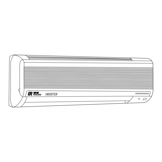
Contents 1. Designations and functions of air conditioner parts......1 2. External dimensi ons ...................2 3. Designations and functions of control buttons in remote controller..4 4. Performance parameters................5 5. Circuit principle diagram 6. Refr igerating cycle ...................10 7. Computer-control principle ..............13 8. - Page 3 Introduction to air conditioner parts Indoor unit Return-air Front panel Power plug outlet C C C AMPM CLOCK AMPM on/off Filter screen Air guide WARM COOL Vertical vane Remote controller MIN. Display section Operation section (with front panel opened ) Green signal lamp Operation pilot lamp Emergency operation switch...
-
Page 4: External Dimensi Ons
External dimensions Indoor unit(KFR-25 28 35G/J01,KFR-25 28 35G/J93) Mounting plate Liquid pipe Gas pipe Outer diameter with heat- Power cord insulating layer 35 Drain pipe Outer diameter with heat- insulating layer 28 Wireless remote controller Outdoor unit(KFR-50W2/03,KFR-50W2/93) Fixing hole Two bleed holes Fitting pipe for liquid pipe joint Maintenance board... - Page 5 External dimensions Indoor unit(KFR-55W2/01,KFR-55W2/93) Fixing hole Two bleed holes Fitting pipe for liquid pipe joint Maintenance board Fitting pipe for liquid pipe joint Fitting pipe for gas pipe joint Fitting pipe for gas pipe joint Outdoor unit(KFR-60W2/03,KFR-60W2/93) Fixing hole Two bleed holes Fitting pipe for liquid pipe joint Fitting pipe for...
-
Page 6: Designations And Functions Of Control Buttons In Remote Controller
Designations and functions of control buttons in remote controller Hanging remote series controller Signal-emitting window C C C Operating display AMPM CLOCK AMPM ON/OFF button on/off WARM COOL Temperature regulating button Operation-mode switching button Air-supply-angle Air-speed option button regulating button Sleep setting button Swing button Timed ON button... -
Page 7: Performance Parameters
Performance parameters Model Single unit Double unit 5.0(1.0 6.0)/6.8(1.0 8.0) Refrigerating capacity /heating capacity kW 2.8(0.3 4.0)/4.0(0.3 6.0) 1.85(0.4 2.5)/2.3(0.5 3.5) 0.9(0.2 1.5)/1.5(0.2 2.5) Input power (refrigerating /heating ) 4.5/7.6 Rated current (refrigerating /heating ) 9.5/11.6 220V , 50Hz Power supply Service line capacity Power supply efficiency Fan-motor current... - Page 8 Performance parameters Model Single unit (25) Single unit (35) Double unit Refrigerating capacity /heating capacity kW 3.5(0.3 4.5)/4.5(0.3 6.8) 5.5(1.0 7.0)/7.4(1.0 9.0) 2.5(0.3 4.0)/4.0(0.3 6.0) 1.3(0.2 2.0)/2.0(0.2 3.0) 2.3(0.5 3.5)/2.8(0.5 4.0) 1.0(0.2 2.0)/1.7(0.2 3.0) Input power (refrigerating /heating ) 6.5/12 Rated current (refrigerating /heating ) 5/10 14/16...
- Page 9 Performance parameters Model Single unit Double unit 6.0(1.0 7.0)/7.6(1.0 9.0) Refrigerating capacity /heating capacity kW 3.5(0.3 4.5)/4.5(0.3 6.8) 2.35(0.5 3.5)/2.8(0.5 4.0) 1.3(0.2 2.0)/2.0(0.2 3.0) Input power (refrigerating /heating ) 6.5/12.0 Rated current (refrigerating /heating ) 14.5/16.0 220V , 50Hz Power supply Service line capacity Power supply efficiency Fan-motor current...
- Page 10 Refrigerating circuit Maxinmum length of fitting pipe Outer diameter of fitting pipe : (mm) Maximum length of extended Model fitting pipe A (m) Liquid pipe Gas pipe Maximum height differenc Indook uint Maximum height difference 5m (regardless either unit is Maximum length of extended fitting pipe A higher) Outdook unit...
-
Page 11: Wireless Remote Controller
Microcomputer control principle Wireless remote controller " Once the control content is set properly, turn on the power supply switch, identical operation will be repeated. " Press a button in remote controller, and the indoor unit will give out a sound toot when it receives a signal. - Page 12 Microcomputer control principle Note: In dehumidifying operation mode of temperature-regulating operation (I FEEL DRY), temperature setting cannot be changed. Press to raise temperature setting for 1~ 2 WARM Press to reduce temperature setting for 1 ~2 COOL When the system is in operation (automatic or manual refrigeration, manual dehumidification), the operation pilot lamp is on;...
- Page 13 Microcomputer control principle 3. High-temperature protection of outdoor heat exchanger In refrigerating operation, temperature T of outdoor unit's coil pipe rises to , it enters into high-temperature protection of outdoor heat exchanger; in high-temperature protection mode, the corresponding variations of temperature points and compressor frequency are shown as below: T coil pipe Unindependent Tcoil pipe...
- Page 14 Microcomputer control principle 2) Cold air prevention a. When temperature of indoor coil pipe is lower than 27 , higher than or equal to 24 , indoor blower fan runs for sleeping air supply; b. When temperature of indoor coil pipe is higher than 27 , lower than or equal to 35 , indoor blower fan rus for low air supply;...
-
Page 15: Computer-Control Principle
Microcomputer control principle 4. Control of four-way valve Heating operation ON (coil powerd on) Refrigerating operation ON (coil powered off ) Dehumidifying operation ON (coil powered off ) 5 seconds 5 seconds Compressor Four-way valve Outdoor fan Refrigerating operation Dehumidifing operation Heating operation Note: four-way valve will commutate for 5 seconds after compressor startup. - Page 16 Microcomputer control principle Heating operation operation ( on/off 1. Press button Indoor unit's operation pilot lamp is on and gives out a sound toot Indoor unit operation , pilot lamp is on and gives out a sound toot 2. Select heating mode ( 3.
- Page 17 Microcomputer control principle 3. Positioning When air-supply angle is changed, vane will firstly turn downwards to its lowest position, and then reach the angle setting. The following conditions may lead to positioning action: (1) When switch button is pressed (ON or OFF); (2) When air guide is switched from automatic tomanual;...
-
Page 18: Timer Operation
Microcomputer control principle Timer operation 1. Timer setting (1) Press ON/OFF button to start up air conditioner . (2) Check if the current time setting is correct: if current time is not set, timer cannot function. Use clock setting button to set current time. (3) Press timed ON button or timed OFF button to select timed operation. - Page 19 Microcomputer control principle Emergency -- test run (1) If remote controller is lost, damaged or its battery is used up, press emergency operation switch on indoor unit's front panel to start up the air conditioner, and the operation pilot lamp is ON. (2) The first 30 minutes is for test run, providing convenience for maintenance reference.
-
Page 20: Au Xiliary Functions 2
Auxiliary functions Forced defrosting operation in maintenance Shortcircuit the socket CN105 on outdoor unit's circuit board, defrosting operation function can be compulsorily executed regardless of the interval of defrosting operation. Here the defrosting operation thermister must be <10 . Time compression function During maintenance, shortcircuit the socket J1 on indoor control circuit board to compress timed time, as shown below: Timed automatic startup: 1 hours 6 minutes... -
Page 21: Installation Diagram
Installation instructions Installation instructions Installation diagram and installation attachments Installation diagram and installation attachments Installation diagram Indoor unit Utilize the marks on indoor unit's mounting plate to determine installing location. Be careful! Do not let drain hose run u p. Fitting pipe of pipeline may be led C C C out from back side, right side, lower... - Page 22 Installation instructions Installation instructions Installation attachments Installation attachments Before installation, check if the following attachments are complete: Enclosed attachments Qty. Mounting plate Qty. Mounting plate Connecting pipe Self-tapping screw ST4*25 Bandage Expansion plug Retaining clamp Expansion bolt Masonry nail Remote controller rest Drain hose Self-tapping screw ST3.5*16 Open-end pipe casing...
- Page 23 Installation instructions Installation instructions How to install indoor unit How to install indoor unit How to fix the mounting plate Find a structural member of a wall (e.g. column etc.), and fix the mounting plate onto it horizontally. Tie the rope at central hole Slotted holes for expansion bolts Not less than 24mm Interval of 450mm at least...
- Page 24 Installation instructions Installation instructions How to install indoor unit How to install indoor unit How to connect wires for indoor/ outdoor units Insulation layer at 2 ends of connecting wire (or extended wire) should be removed. If wire is too long or it is connected at medium section, remove the insulatuion layer as per dimensions shown in right figure.
-
Page 25: Inst Allation Ins Tructions
Installation instructions Installation instructions How to install indoor unit How to install indoor unit Gas pipe Liquid pipe Installation of fitting pipe Precautions Drain hose Drain hose must be located below the coolant pipeline; Do not hunch up or bend the drain hoses; Heat-insulation cushion Do not pull at the drain hose to carry out wrapping operation;... - Page 26 Installation instructions Installation instructions How to install outdoor unit How to install outdoor unit How to install indoor unit The number of bends in pipeline of indoor unit must not be over 10, and the number of bends in the entire the system must not be over 15;...
- Page 27 Installation instructions Installation instructions How to install indoor unit How to install indoor unit Installation of drain joint When air conditioner is in heating operation, condensed water from outdoor unit, and defrosting water from defrosting operation can be drain to appropriate place via drain pipe.
-
Page 28: Test Run
Installation instructions Installation instructions Refrigerant replenishing method and test run Refrigerant replenishing method Detailed procedures: Connect the gas storage cylinder to access door of gas valve; Utilize the gas from pipeline (or hose) of refrigerant gas storage cylinder to carry out air purge; Replenish refrigerant of appointed volume for normal operation of air regulator. - Page 29 Installation instructions Installation instructions Precautions on troubleshooting Precautions on troubleshooting I. Before troubleshooting, check if the supply voltage is normal, and check if the connecting wires of indoor/ outdoor are correctly connected. II. The following aspects should be taken into account during maintenance: 1.
- Page 30 Installation instructions Installation instructions Trouble selfcheck table Trouble selfcheck table I. Selfcheck table for trouble in indoor unit: Operation lamp flickers Trouble content Maintenance 1. Replace indoor sensor Flicker once, and stop flickering Indoor sensor is damaged 2. If the trouble remains the same, replace indoor control for 3 seconds panel 1.
- Page 31 Trouble and maintenance Trouble and maintenance Trouble selfcheck table Trouble selfcheck table IV. Power indicator LED101 of outdoor unit IV. Power indicator LED101 of outdoor unit After outdoor circuit board is powered on, the LED is normally on. When LED101 is off, it indicates that the outdoor circuit board is uncharged. Caution: Since the outdoor electrolytic capacitor has a storage effect, and the residual high- voltage charge still remains in the outdoor circuit board after power-off, no operation on the outdoor circuit board shall be performed unless the LED101 is off.
- Page 32 Trouble and maintenance Trouble and maintenance Module Judgment Module Judgment How to judge short circuit in power transistor: Unplug the 10-core plug of module, the plug of link module of compressor, and the plugs of 1. In the case of short circuit Whenever a short circuit occurs in the power transistor, it must be a short circuit between the collector anode and the semiconductor.
- Page 33 Trouble and maintenance Trouble and maintenance Outdoor unit inspection Outdoor unit inspection Beginning Refer to trouble selfcheck table Check if trouble indication is normal for outdoor unit . 1. Check if the voltage between pole 8 and pole 7 of CN101 is 5VDC.
- Page 34 Trouble and maintenance Trouble and maintenance A.Inspection of indoor fan motor Switch off the power supply, and check socket Cn5. Check if the wire is in good condition Check if the solder points are normal. Connect the wires properly Re-solder it Unplug the wire from the socket CN5 on indoor unit's circuit board, and determine the DC resistances between (1)~(3) and the resistance between(1) ~(5).
- Page 35 » ª Á è Ö Ð Ñ ë ¿ Õ µ ÷ É è ± ¸ Ó Ð Ï Þ ¹ » ª Á è Ö Ð Ñ ë ¿ Õ µ ÷ É è ± ¸ Ó Ð Ï Þ ¹ Address: Dashi, Panyu, Guangzhou Version 2003.10...
Need help?
Do you have a question about the KFR-25G/J01 and is the answer not in the manual?
Questions and answers