Table of Contents
Advertisement
Advertisement
Table of Contents

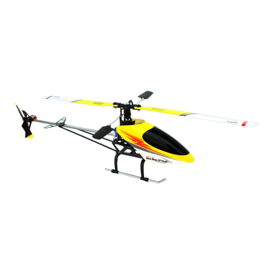
Summary of Contents for Century UK Neon Blaze CP V2.4G
-
Page 2: Table Of Contents
Gyro sensitivity and Rudder Mixing adjustment Main Rotor Blade Adjustment Tail Rotor Blade Adjustment Technical Data for Adjustment The Disassembly Steps of Rotor Head The Assembly Steps of Rotor Head Exploded Diagram for Neon Blaze CP V2.4G Upgrade Flight Mode... -
Page 4: Getting Started Home Check List
Getting started home check list 1. READ THE USER MANUAL FROM COVER TO COVER, even if you think that you do not understand all the information in the manual it will all help when you start to fly. 2. Expect it to take you at least 5 hours of practice to learn to hover, some take less but if you expect it to take you longer then you will not get frustrated. -
Page 5: Cautions
Cautions 1. Because the helicopter is operated by radio control, it is important to make sure you are always using fresh and/ or fully charged batteries. Never allow the batteries to run low, or you could lose control of the helicopter. 2. - Page 6 6-CH Transmitter Features: ( MODE lI ) 1. The DIP switches are available for various servos. It can perform the flight actions such as Gear ascending, descending, forward, backward, leftward, rightward and so on. PIT limit / Exponential / Rudder mixing (V2) 2.
-
Page 7: Receiver Ldentification
Receiver Identification Receiver Identification (Fig. 3): Fig. 3 ⑧ 1. ELEV. : Connect to the elevator servo. ⑦ ⑥ 2. AILE. : Connect to the aileron servo. ⑤ 3. PIT. : Connect to the PIT servo. ④ ③ ② 4. RUDD. : Connect to the tail servo. ①... -
Page 8: Battery Mounting And Adjustment
Battery Mounting and Adjustment 1. Battery pack mounting. Place the battery pack in the correct position of your helicopter Fig. 5 (Fig. 5). 2. CG balance. Put your helicopter in a horizontal ground and make the flybar vertical to the tail boom of your helicopter. -
Page 9: Pit Adjustment And Locking
4. After the adjustment is finished, turn the No.10 DIP switch to "OFF" position. the regulated servo exponential parameters have been locked. Fig. 9 Fig. 10 Fig. 8 PIT adjustment and locking The transmitter provides PIT adjustment and PIT extent adjustment and can lock the adjustment parameters as below: 、... -
Page 10: Gyro Sensitivity And Rudder Mixing Adjustment
Gyro sensitivity and Rudder Mixing adjustment You can adjust the gyro sensitivity and Rudder Mixing adjustment after locking the PIT parameters. The methods are shown as follows: 1. Turn the No.12 DIP switch to "ON" position, aim the V1、V2 knob on the transmitter panel to "0" position. 2. -
Page 11: Technical Data For Adjustment
Technical Data for Adjustment Upgrade Plastic rotor head Metal rotor head 48mm 6.5mm 10mm 6.8mm 12.5mm The Disassembly Steps of Rotor Head Main rotor blade Hexagon socket pan head locking screw (M3*14) 1. Unscrew the hexagon socket head cap screw (M3*14),and take down the main rotor blades. - Page 12 Hexagon socket head cap screw (M2*10) Linkage rod 2. Remove the linkage rod and unscrew the hexagon socket head cap screw (M2*10). Linkage rod Linkage rod Linkage rod 3. Take down the linkage rod and the plastic rotor head set.
-
Page 13: The Assembly Steps Of Rotor Head
4. The disassembled profile. The Assembly Steps of Rotor Head Flybar set Swashplate Ball linkage set Rotor head set ① 1. Metal rotor head set. 2. Hexagon socket flat head cap screw (M3*10) / Locking socket nut (M3). ② 3. Hexagon socket head cap screw (M2*10) / Type-1 hexagonal nut (M2). ③... - Page 14 1. Assemble the metal rotor head set and linkage rod. 2. Tighten the hexagon socket head cap screw (M2*10), and then set up the linkage rod.
- Page 15 3. Set up the main rotor blades, and tighten the hexagon socket flat head cap screw (M3*10). 4. The assembled profile.
-
Page 16: Exploded Diagram For Neon Blaze Cp V2.4G Upgrade
Exploded Diagram for Neon Blaze CP V2.4G Upgrade... -
Page 17: Flight Mode
Flight Mode MODE Il Inverted Flight Mode throttle pushing ascending throttle pulling descending down rudder stick head turning moving left left head turning rudder stick right moving right head forward elevator stick pushing up head backward elevator stick pulling down helicopter aileron stick moving left...

Need help?
Do you have a question about the Neon Blaze CP V2.4G and is the answer not in the manual?
Questions and answers