Table of Contents
Advertisement
Quick Links
CESSNA
INTRODUCTION
MODEL T182T NAV III
GFC 700 AFCS
NOTICE
AT THE TIME OF ISSUANCE, THIS INFORMATION
MANUAL WAS AN EXACT DUPLICATE OF THE
OFFICIAL PILOT'S OPERATING HANDBOOK AND
FAA APPROVED AIRPLANE FLIGHT MANUAL AND
IS TO BE USED FOR GENERAL PURPOSES ONLY.
IT
WILL
NOT
BE
KEPT
CURRENT
AND,
THEREFORE,
CANNOT
BE
USED
AS
A
SUBSTITUTE
FOR
THE
OFFICIAL
PILOT'S
OPERATING HANDBOOK AND FAA APPROVED
AIRPLANE
FLIGHT
MANUAL
INTENDED
FOR
OPERATION OF THE AIRPLANE.
THE PILOT'S OPERATING HANDBOOK MUST BE
CARRIED IN THE AIRPLANE AND AVAILABLE TO
THE PILOT AT ALL TIMES.
Cessna Aircraft Company
Original Issue - 27 October 2006
Revision 1 - 20 December 2007
Revision 1
i
U.S.
Advertisement
Chapters
Table of Contents

Related Manuals for Cessna skylance tc T182T

Summary of Contents for Cessna skylance tc T182T
- Page 1 OPERATION OF THE AIRPLANE. THE PILOT’S OPERATING HANDBOOK MUST BE CARRIED IN THE AIRPLANE AND AVAILABLE TO THE PILOT AT ALL TIMES. Cessna Aircraft Company Original Issue - 27 October 2006 Revision 1 - 20 December 2007 Revision 1 U.S.
- Page 2 INTRODUCTION CESSNA MODEL T182T NAV III GFC 700 AFCS PERFORMANCE - SPECIFICATIONS *SPEED: Maximum at 20,000 Feet ......176 KNOTS Cruise, 88% Power at 12,500 Feet .
- Page 3 The above performance figures are based on the indicated weights, standard atmospheric conditions, level, hard-surface dry runways and no wind. They are calculated values derived from flight tests conducted by Cessna Aircraft Company under carefully documented conditions and will vary with individual airplanes and numerous factors affecting flight performance.
- Page 5 CESSNA INTRODUCTION MODEL T182T NAV III GFC 700 AFCS Cessna Aircraft Company Model T182T NAV III AVIONICS OPTION - GFC 700 AFCS Serials T18208665 and T18208669 and On THIS MANUAL INCORPORATES INFORMATION ISSUED IN THE PILOT'S OPERATING HANDBOOK APPROVED AIRPLANE FLIGHT MANUAL AT REVISION 1, DATED 20 DECEMBER 2007 (PART NUMBER T182TPHBUS-01).
-
Page 7: Table Of Contents
CESSNA INTRODUCTION MODEL T182T NAV III GFC 700 AFCS TABLE OF CONTENTS SECTION GENERAL ..........1 LIMITATIONS. - Page 9 CESSNA SECTION 1 MODEL T182T NAV III GENERAL GFC 700 AFCS GENERAL TABLE OF CONTENTS Page Three View - Normal Ground Attitude ......1-3 Introduction .
-
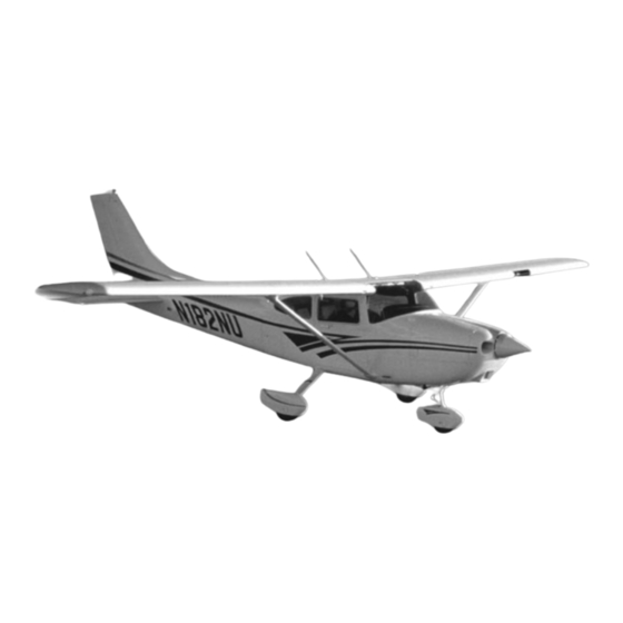
Page 11: Three View - Normal Ground Attitude
CESSNA SECTION 1 MODEL T182T NAV III GENERAL GFC 700 AFCS THREE VIEW - NORMAL GROUND ATTITUDE Figure 1-1 (Sheet 1 of 2) T182TPHBUS-00 U.S. - Page 12 SECTION 1 CESSNA GENERAL MODEL T182T NAV III GFC 700 AFCS THREE VIEW - NORMAL GROUND ATTITUDE NOTE • Wing span shown with standard strobe lights installed. • Wheel base length is 66.5 inches. • Propeller ground clearance is 10.875 inches.
-
Page 13: Introduction
This POH contains 9 sections, and includes the material required to be furnished to the pilot by 14 CFR 23. It also contains supplemental data supplied by Cessna Aircraft Company. Section 1 provides basic data and information of general interest. It also contains definitions or explanations of symbols, abbreviations, and terminology commonly used. -
Page 14: Fuel
SECTION 1 CESSNA GENERAL MODEL T182T NAV III GFC 700 AFCS DESCRIPTIVE DATA (Continued) FUEL WARNING USE OF UNAPPROVED FUELS MAY RESULT IN DAMAGE TO THE ENGINE AND FUEL SYSTEM COMPONENTS, RESULTING IN POSSIBLE ENGINE FAILURE. Approved Fuel Grades (and Colors):... -
Page 15: Oil
CESSNA SECTION 1 MODEL T182T NAV III GENERAL GFC 700 AFCS DESCRIPTIVE DATA (Continued) OIL SPECIFICATION MIL-L-22851 or SAE J1899 Aviation Grade Ashless Dispersant Oil: Oil conforming to Textron Lycoming Service Instruction No 1014, and all revisions and supplements thereto, must be used. -
Page 16: Maximum Certificated Weights
SECTION 1 CESSNA GENERAL MODEL T182T NAV III GFC 700 AFCS DESCRIPTIVE DATA (Continued) MAXIMUM CERTIFICATED WEIGHTS Ramp Weight ....... . . 3112 POUNDS Takeoff Weight . -
Page 17: Symbols, Abbreviations And Terminology
CESSNA SECTION 1 MODEL T182T NAV III GENERAL GFC 700 AFCS SYMBOLS, ABBREVIATIONS AND TERMINOLOGY GENERAL AIRSPEED TERMINOLOGY AND SYMBOLS KCAS Knots Calibrated Airspeed is indicated airspeed corrected for position and instrument error and expressed in knots. Knots calibrated airspeed is equal to KTAS in standard atmosphere at sea level. -
Page 18: Meteorological Terminology
SECTION 1 CESSNA GENERAL MODEL T182T NAV III GFC 700 AFCS SYMBOLS, ABBREVIATIONS AND TERMINOLOGY (Continued) METEOROLOGICAL TERMINOLOGY Outside Air Temperature is the free air static temperature. It may be expressed in either degrees Celsius or degrees Fahrenheit. Standard Temperature Standard Temperature is 15°C at sea level pressure altitude and decreases by 2°C for each 1000 feet of... - Page 19 CESSNA SECTION 1 MODEL T182T NAV III GENERAL GFC 700 AFCS SYMBOLS, ABBREVIATIONS AND TERMINOLOGY (Continued) ENGINE POWER TERMINOLOGY (Continued) Lean Mixture Decreased proportion of fuel in the fuel-air mixture supplied to the engine. As air density decreases, the amount of fuel required by the engine decreases for a given throttle setting.
-
Page 20: Airplane Performance And Flight Planning Terminology
SECTION 1 CESSNA GENERAL MODEL T182T NAV III GFC 700 AFCS SYMBOLS, ABBREVIATIONS AND TERMINOLOGY (Continued) AIRPLANE PERFORMANCE AND FLIGHT PLANNING TERMINOLOGY Demonstrated Crosswind Velocity Demonstrated Crosswind Velocity is the velocity of the crosswind component for which adequate control of the airplane during takeoff and landing was actually demonstrated during certification tests. -
Page 21: Weight And Balance Terminology
CESSNA SECTION 1 MODEL T182T NAV III GENERAL GFC 700 AFCS SYMBOLS, ABBREVIATIONS AND TERMINOLOGY (Continued) WEIGHT AND BALANCE TERMINOLOGY Reference Datum Reference Datum is an imaginary vertical plane from which all horizontal distances are measured for balance purposes. Station Station is a location along the airplane fuselage given in terms of the distance from the reference datum. - Page 22 SECTION 1 CESSNA GENERAL MODEL T182T NAV III GFC 700 AFCS SYMBOLS, ABBREVIATIONS AND TERMINOLOGY (Continued) WEIGHT AND BALANCE TERMINOLOGY (Continued) Basic Empty Weight Basic Empty Weight is the standard empty weight plus the weight of optional equipment. Useful Load Useful Load is the difference between ramp weight and the basic empty weight.
-
Page 23: Metric/Imperial/U.s. Conversion Charts
CESSNA SECTION 1 MODEL T182T NAV III GENERAL GFC 700 AFCS METRIC/IMPERIAL/U.S. CONVERSION CHARTS The following charts have been provided to help international operators convert U.S. measurement supplied with the Pilot’s Operating Handbook into metric and imperial measurements. The standard followed for measurement units shown is the National Institute of Standards Technology (NIST), Publication 811, "Guide for... -
Page 24: Weight Conversions
SECTION 1 CESSNA GENERAL MODEL T182T NAV III GFC 700 AFCS WEIGHT CONVERSIONS Figure 1-2 (Sheet 1 of 2) T182TPHBUS-01 1-16 U.S. - Page 25 CESSNA SECTION 1 MODEL T182T NAV III GENERAL GFC 700 AFCS WEIGHT CONVERSIONS Figure 1-2 (Sheet 2) T182TPHBUS-01 1-17 U.S.
-
Page 26: Length Conversions
SECTION 1 CESSNA GENERAL MODEL T182T NAV III GFC 700 AFCS LENGTH CONVERSIONS Figure 1-3 (Sheet 1 of 4) T182TPHBUS-01 1-18 U.S. - Page 27 CESSNA SECTION 1 MODEL T182T NAV III GENERAL GFC 700 AFCS LENGTH CONVERSIONS Figure 1-3 (Sheet 2) T182TPHBUS-01 1-19 U.S.
- Page 28 SECTION 1 CESSNA GENERAL MODEL T182T NAV III GFC 700 AFCS LENGTH CONVERSIONS Figure 1-3 (Sheet 3) T182TPHBUS-01 1-20 U.S.
- Page 29 CESSNA SECTION 1 MODEL T182T NAV III GENERAL GFC 700 AFCS LENGTH CONVERSIONS Figure 1-3 (Sheet 4) T182TPHBUS-01 1-21 U.S.
-
Page 30: Distance Conversions
SECTION 1 CESSNA GENERAL MODEL T182T NAV III GFC 700 AFCS DISTANCE CONVERSIONS Figure 1-4 T182TPHBUS-01 1-22 U.S. -
Page 31: Volume Conversions
CESSNA SECTION 1 MODEL T182T NAV III GENERAL GFC 700 AFCS VOLUME CONVERSIONS Figure 1-5 (Sheet 1 of 3) T182TPHBUS-01 1-23 U.S. - Page 32 SECTION 1 CESSNA GENERAL MODEL T182T NAV III GFC 700 AFCS VOLUME CONVERSIONS Figure 1-5 (Sheet 2) T182TPHBUS-01 1-24 U.S.
- Page 33 CESSNA SECTION 1 MODEL T182T NAV III GENERAL GFC 700 AFCS VOLUME CONVERSIONS Figure 1-5 (Sheet 3) T182TPHBUS-01 1-25 U.S.
-
Page 34: Temperature Conversions
SECTION 1 CESSNA GENERAL MODEL T182T NAV III GFC 700 AFCS TEMPERATURE CONVERSIONS Figure 1-6 T182TPHBUS-01 1-26 U.S. -
Page 35: Pressure Conversion
CESSNA SECTION 1 MODEL T182T NAV III GENERAL GFC 700 AFCS PRESSURE CONVERSION HECTOPASCALS TO INCHES OF MERCURY Figure 1-7 T182TPHBUS-01 1-27 U.S. -
Page 36: Volume To Weight Conversion
SECTION 1 CESSNA GENERAL MODEL T182T NAV III GFC 700 AFCS VOLUME TO WEIGHT CONVERSION Figure 1-8 T182TPHBUS-01 1-28 U.S. -
Page 37: Quick Conversions
CESSNA SECTION 1 MODEL T182T NAV III GENERAL GFC 700 AFCS QUICK CONVERSIONS Figure 1-9 T182TPHBUS-01 1-29/1-30 U.S. -
Page 39: Limitations
CESSNA SECTION 2 MODEL T182T NAV III OPERATING LIMITATIONS GFC 700 AFCS OPERATING LIMITATIONS TABLE OF CONTENTS Page Introduction ..........2-3 Airspeed Limitations . -
Page 41: Introduction
Section The Cessna Model No. T182T is certificated under FAA Type Certificate No. 3A13. FAA APPROVED T182TPHBUS-00 U.S. -
Page 42: Airspeed Limitations
SECTION 2 CESSNA OPERATING LIMITATIONS MODEL T182T NAV III GFC 700 AFCS AIRSPEED LIMITATIONS Airspeed limitations and their operational significance are shown in Figure 2-1. AIRSPEED LIMITATIONS SYMBOL SPEED KCAS KIAS REMARKS Never Exceed Speed Do not exceed this speed in any operation. -
Page 43: Airspeed Indicator Markings
CESSNA SECTION 2 MODEL T182T NAV III OPERATING LIMITATIONS GFC 700 AFCS AIRSPEED INDICATOR MARKINGS Airspeed indicator markings and their color code significance are shown in Figure 2-2. AIRSPEED INDICATOR MARKINGS KIAS VALUE OR MARKING SIGNIFICANCE RANGE Red Arc* 20 - 41 Low airspeed warning. -
Page 44: Powerplant Limitations
SECTION 2 CESSNA OPERATING LIMITATIONS MODEL T182T NAV III GFC 700 AFCS POWERPLANT LIMITATIONS Engine Manufacturer: Textron Lycoming Engine Model Number: TIO-540-AK1A Engine Operating Limits for Takeoff and Continuous Operations: Maximum Continuous Power: ....235 rated BHP at 32 in.hg. -
Page 45: Powerplant Instrument Markings
CESSNA SECTION 2 MODEL T182T NAV III OPERATING LIMITATIONS GFC 700 AFCS POWERPLANT INSTRUMENT MARKINGS Powerplant instrument markings and their color code significance are shown in Figure 2-3. Operation with indications in the red range is prohibited. Avoid operating with indicators in the yellow range. -
Page 46: Weight Limits
SECTION 2 CESSNA OPERATING LIMITATIONS MODEL T182T NAV III GFC 700 AFCS WEIGHT LIMITS Maximum Ramp Weight: ......3112 POUNDS Maximum Takeoff Weight: . -
Page 47: Maneuver Limits
KINDS OF OPERATIONS LIMITS The Cessna T182T Nav III airplane is approved for day and night, VFR and IFR operations. Flight into known icing conditions is prohibited. The minimum equipment for approved operations required under the Operating Rules are defined by 14 CFR 91 and 14 CFR 135, as applicable. -
Page 48: Kinds Of Operations Equipment List
SECTION 2 CESSNA OPERATING LIMITATIONS MODEL T182T NAV III GFC 700 AFCS KINDS OF OPERATIONS EQUIPMENT LIST KIND OF OPERATION System, Instrument, Equipment and/or Function COMMENTS PLACARDS AND MARKINGS T182T Nav III - GFC 700 AFCS Accessible to pilot in flight. - Page 49 CESSNA SECTION 2 MODEL T182T NAV III OPERATING LIMITATIONS GFC 700 AFCS KINDS OF OPERATIONS EQUIPMENT LIST (Continued) KIND OF OPERATION System, Instrument, Equipment and/ or Function COMMENTS EQUIPMENT AND FURNISHINGS 1 - Seat Belt Assembly Each Seat Occupant 2 - Shoulder Harness...
- Page 50 SECTION 2 CESSNA OPERATING LIMITATIONS MODEL T182T NAV III GFC 700 AFCS KINDS OF OPERATIONS EQUIPMENT LIST (Continued) KIND OF OPERATION System, Instrument, Equipment and/or Function COMMENTS LIGHTING 1 - PFD Bezel Lighting 2 - PFD Backlighting *Refer to Note 2.
- Page 51 CESSNA SECTION 2 MODEL T182T NAV III OPERATING LIMITATIONS GFC 700 AFCS KINDS OF OPERATIONS EQUIPMENT LIST (Continued) KIND OF OPERATION System, Instrument, Equipment and/or Function COMMENTS NAVIGATION AND PITOT- STATIC SYSTEM 1 - G1000 Airspeed Indicator 2 - Standby Airspeed Indicator...
- Page 52 SECTION 2 CESSNA OPERATING LIMITATIONS MODEL T182T NAV III GFC 700 AFCS KINDS OF OPERATIONS EQUIPMENT LIST (Continued) KIND OF OPERATION System, Instrument, Equipment and/or Function COMMENTS VACUUM 1 - Engine Driven Vacuum Pump 2 - Vacuum Indicator ENGINE FUEL AND CONTROL...
-
Page 53: Fuel Limitations
CESSNA SECTION 2 MODEL T182T NAV III OPERATING LIMITATIONS GFC 700 AFCS FUEL LIMITATIONS Total Fuel: ....92.0 U.S. Gallons (46.0 gallons per tank) Usable Fuel: ... . . 87.0 U.S. Gallons (43.5 gallons per tank) Unusable Fuel:. -
Page 54: System Limitations
SECTION 2 CESSNA OPERATING LIMITATIONS MODEL T182T NAV III GFC 700 AFCS SYSTEM LIMITATIONS AUX AUDIO SYSTEM Use of the AUX AUDIO IN entertainment input is prohibited during takeoff and landing. Use of the AUX AUDIO IN entertainment audio input and portable... - Page 55 CESSNA SECTION 2 MODEL T182T NAV III OPERATING LIMITATIONS GFC 700 AFCS G1000 LIMITATIONS The current Garmin G1000 Cockpit Reference Guide (CRG) Part Number and System Software Version that must be available to the pilot during flight are displayed on the MFD AUX group, SYSTEM STATUS page.
-
Page 56: G1000 Limitations
SECTION 2 CESSNA OPERATING LIMITATIONS MODEL T182T NAV III GFC 700 AFCS G1000 LIMITATIONS (Continued) The COM 1/2 (split COM) function of the Audio Panel is not approved for use. During COM 1/2 operation, transmission by one crew member inhibits reception by the other crew member. -
Page 57: Garmin Gfc 700 Afcs
CESSNA SECTION 2 MODEL T182T NAV III OPERATING LIMITATIONS GFC 700 AFCS G1000 LIMITATIONS (Continued) GARMIN GFC 700 AFCS 1. The GFC 700 AFCS preflight test must be successfully completed prior to use of the autopilot, flight director or manual electric trim. -
Page 58: Traffic Advisory System (Tas)
SECTION 2 CESSNA OPERATING LIMITATIONS MODEL T182T NAV III GFC 700 AFCS G1000 LIMITATIONS (Continued) TRAFFIC ADVISORY SYSTEM (TAS) Use of the TRAFFIC MAP to maneuver the airplane to avoid traffic is prohibited. The Traffic Advisory System (TAS) is intended for advisory use only. -
Page 59: Placards
CESSNA SECTION 2 MODEL T182T NAV III OPERATING LIMITATIONS GFC 700 AFCS PLACARDS The following information must be displayed in the form of composite or individual placards. 1. In full view of the pilot: (The "DAY-NIGHT-VFR-IFR" entry, shown on the example below, will vary with installed equipment). - Page 60 SECTION 2 CESSNA OPERATING LIMITATIONS MODEL T182T NAV III GFC 700 AFCS PLACARDS (Continued) 3. On the fuel selector valve: 4. Near both fuel tank filler cap: (Continued Next Page) FAA APPROVED T182TPHBUS-00 2-22 U.S.
- Page 61 CESSNA SECTION 2 MODEL T182T NAV III OPERATING LIMITATIONS GFC 700 AFCS PLACARDS (Continued) 5. On flap control indicator: 6. In baggage compartment: (Continued Next Page) FAA APPROVED T182TPHBUS-00 2-23 U.S.
- Page 62 SECTION 2 CESSNA OPERATING LIMITATIONS MODEL T182T NAV III GFC 700 AFCS PLACARDS (Continued) 7. A calibration card must be provided to indicate the accuracy of the magnetic compass in 30° increments. 8. Molded on the oil filler cap/dipstick: 9. Silk-screened on the instrument panel directly above the PFD:...
- Page 63 CESSNA SECTION 2 MODEL T182T NAV III OPERATING LIMITATIONS GFC 700 AFCS PLACARDS (Continued) 10.Silk-screened on the upper right instrument panel: 11.On auxiliary power plug door and second placard on battery box: 12.On the upper right side of the aft cabin partition:...
- Page 64 SECTION 2 CESSNA OPERATING LIMITATIONS MODEL T182T NAV III GFC 700 AFCS PLACARDS (Continued) 13.On the center overhead flood light control switch: FAA APPROVED T182TPHBUS-01 2-26 U.S.
- Page 65 CESSNA SECTION 3 MODEL T182T NAV III EMERGENCY PROCEDURES GFC 700 AFCS EMERGENCY PROCEDURES TABLE OF CONTENTS Page Introduction ..........3-5 Airspeeds For Emergency Operations.
- Page 66 SECTION 3 CESSNA EMERGENCY PROCEDURES MODEL T182T NAV III GFC 700 AFCS TABLE OF CONTENTS (Continued) Page ABNORMAL LANDINGS....... . 3-16 Landing With A Flat Main Tire .
- Page 67 CESSNA SECTION 3 MODEL T182T NAV III EMERGENCY PROCEDURES GFC 700 AFCS TABLE OF CONTENTS (Continued) Page AMPLIFIED EMERGENCY PROCEDURES ....3-25 Engine Failure ......... 3-25 Maximum Glide .
-
Page 69: Introduction
CESSNA SECTION 3 MODEL T182T NAV III EMERGENCY PROCEDURES GFC 700 AFCS INTRODUCTION Section 3 provides checklist and amplified procedures for coping with emergencies that may occur. Emergencies caused by airplane or engine malfunctions are extremely rare if proper preflight inspections and maintenance are practiced. -
Page 70: Emergency Procedures
SECTION 3 CESSNA EMERGENCY PROCEDURES MODEL T182T NAV III GFC 700 AFCS EMERGENCY PROCEDURES Procedures in the Emergency Procedures Checklist portion of this section shown in bold faced type are immediate action items which should be committed to memory. ENGINE FAILURES ENGINE FAILURE DURING TAKEOFF ROLL 1. -
Page 71: Engine Failure During Flight (Restart Procedures)
CESSNA SECTION 3 MODEL T182T NAV III EMERGENCY PROCEDURES GFC 700 AFCS ENGINE FAILURES (Continued) ENGINE FAILURE DURING FLIGHT (Restart Procedures) 1. Airspeed - 75 KIAS (best glide speed) 2. FUEL SELECTOR Valve - BOTH 3. FUEL PUMP Switch - ON 4. -
Page 72: Forced Landings
SECTION 3 CESSNA EMERGENCY PROCEDURES MODEL T182T NAV III GFC 700 AFCS FORCED LANDINGS EMERGENCY LANDING WITHOUT ENGINE POWER 1. Pilot and Passenger Seat Backs - MOST UPRIGHT POSITION 2. Seats and Seat Belts - SECURE 3. Airspeed - 75 KIAS - Flaps UP 70 KIAS - Flaps 10°... -
Page 73: Ditching
CESSNA SECTION 3 MODEL T182T NAV III EMERGENCY PROCEDURES GFC 700 AFCS FORCED LANDINGS (Continued) DITCHING 1. Radio - TRANSMIT MAYDAY on 121.5 MHz, (give location, intentions and SQUAWK 7700) 2. Heavy Objects (in baggage area) - SECURE OR JETTISON (if possible) 3. -
Page 74: Fires
SECTION 3 CESSNA EMERGENCY PROCEDURES MODEL T182T NAV III GFC 700 AFCS FIRES DURING START ON GROUND 1. MAGNETOS Switch - START (continue cranking to start the engine) IF ENGINE STARTS 2. Power - 1800 RPM (for a few minutes) 3. -
Page 75: Engine Fire In Flight
CESSNA SECTION 3 MODEL T182T NAV III EMERGENCY PROCEDURES GFC 700 AFCS FIRES (Continued) ENGINE FIRE IN FLIGHT 1. Mixture Control - IDLE CUTOFF (pull full out) 2. FUEL SELECTOR Valve - PUSH DOWN and ROTATE to OFF 3. FUEL PUMP Switch - OFF 4. -
Page 76: Cabin Fire
SECTION 3 CESSNA EMERGENCY PROCEDURES MODEL T182T NAV III GFC 700 AFCS FIRES (Continued) ELECTRICAL FIRE IN FLIGHT (Continued) IF FIRE HAS BEEN EXTINGUISHED AND ELECTRICAL POWER IS NECESSARY FOR CONTINUED FLIGHT TO NEAREST SUITABLE AIRPORT OR LANDING AREA 10. Circuit Breakers - CHECK (for OPEN circuit(s), do not reset) 11. -
Page 77: Wing Fire
CESSNA SECTION 3 MODEL T182T NAV III EMERGENCY PROCEDURES GFC 700 AFCS FIRES (Continued) WING FIRE 1. LAND and TAXI Light Switches - OFF 2. NAV Light Switch - OFF 3. STROBE Light Switch - OFF 4. PITOT HEAT Switch - OFF... -
Page 78: Icing
SECTION 3 CESSNA EMERGENCY PROCEDURES MODEL T182T NAV III GFC 700 AFCS ICING INADVERTENT ICING ENCOUNTER DURING FLIGHT 1. PITOT HEAT Switch - ON 2. PROP HEAT Switch - ON 3. Turn back or change altitude (to obtain an outside air temperature that is less conducive to icing) 4. -
Page 79: Static Source Blockage
CESSNA SECTION 3 MODEL T182T NAV III EMERGENCY PROCEDURES GFC 700 AFCS ICING (Continued) INADVERTENT ICING ENCOUNTER DURING FLIGHT (Continued) 11. Open left window and, if practical, scrape ice from a portion of the windshield for visibility in the landing approach. -
Page 80: Excessive Fuel Vapor
SECTION 3 CESSNA EMERGENCY PROCEDURES MODEL T182T NAV III GFC 700 AFCS EXCESSIVE FUEL VAPOR FUEL FLOW STABILIZATION PROCEDURES (If flow fluctuations of 1 GPH or more, or power surges occur.) 1. FUEL PUMP Switch - ON 2. Mixture Control - ADJUST (as necessary for smooth engine operation) 3. -
Page 81: Electrical Power Supply System Malfunctions
CESSNA SECTION 3 MODEL T182T NAV III EMERGENCY PROCEDURES GFC 700 AFCS ELECTRICAL POWER SUPPLY SYSTEM MALFUNCTIONS HIGH VOLTS ANNUNCIATOR COMES ON OR M BATT AMPS MORE THAN 40 1. MASTER Switch (ALT Only) - OFF 2. Electrical Load - REDUCE IMMEDIATELY as follows: a. - Page 82 SECTION 3 CESSNA EMERGENCY PROCEDURES MODEL T182T NAV III GFC 700 AFCS ELECTRICAL POWER SUPPLY SYSTEM MALFUNCTIONS (Continued) HIGH VOLTS ANNUNCIATOR COMES ON OR M BATT AMPS MORE THAN 40 (Continued) COM1 and NAV1 - TUNE TO ACTIVE FREQUENCY k. COM1 MIC and NAV1 - SELECT (COM2 MIC and NAV2 will...
-
Page 83: Low Volts Annunciator Comes On Below 1000 Rpm
CESSNA SECTION 3 MODEL T182T NAV III EMERGENCY PROCEDURES GFC 700 AFCS ELECTRICAL POWER SUPPLY SYSTEM MALFUNCTIONS (Continued) LOW VOLTS ANNUNCIATOR COMES ON BELOW 1000 1. Throttle Control - 1000 RPM 2. LOW VOLTS Annunciator - CHECK OFF LOW VOLTS ANNUNCIATOR REMAINS ON AT 1000 RPM 3. - Page 84 SECTION 3 CESSNA EMERGENCY PROCEDURES MODEL T182T NAV III GFC 700 AFCS ELECTRICAL POWER SUPPLY SYSTEM MALFUNCTIONS (Continued) IF LOW VOLTS ANNUNCIATOR REMAINS ON (Continued) NOTE • The Main Battery supplies electrical power to the Main and Essential Buses until M BUS VOLTS decreases below 20 volts.
-
Page 85: Air Data System Failure
CESSNA SECTION 3 MODEL T182T NAV III EMERGENCY PROCEDURES GFC 700 AFCS AIR DATA SYSTEM FAILURE RED X - PFD AIRSPEED INDICATOR 1. ADC/AHRS Circuit Breakers - CHECK IN (ESS BUS and AVN BUS 1). If open, reset (close) circuit breaker. If circuit breaker opens again, do not reset. -
Page 86: Autopilot Or Electric Trim Failure
SECTION 3 CESSNA EMERGENCY PROCEDURES MODEL T182T NAV III GFC 700 AFCS AUTOPILOT OR ELECTRIC TRIM FAILURE AP OR PTRM ANNUNCIATOR(S) COME ON 1. Control Wheel - GRASP FIRMLY (regain control of airplane) 2. A/P TRIM DISC Button - PRESS and HOLD (throughout recovery) 3. -
Page 87: Display Cooling Advisory
CESSNA SECTION 3 MODEL T182T NAV III EMERGENCY PROCEDURES GFC 700 AFCS DISPLAY COOLING ADVISORY PFD1 COOLING OR MFD1 COOLING ANNUNCIATOR(S) COME ON 1. CABIN HT Control Knob - REDUCE (push in) (minimum preferred) 2. Forward Avionics Fan - CHECK (feel for airflow from screen on... - Page 88 SECTION 3 CESSNA EMERGENCY PROCEDURES MODEL T182T NAV III GFC 700 AFCS HIGH CARBON MONOXIDE (CO) LEVEL ADVISORY CO LVL HIGH ANNUNCIATOR COMES ON 1. CABIN HT Control Knob - OFF (push full in) 2. CABIN AIR Control Knob - ON (pull full out) 3.
-
Page 89: Amplified Emergency Procedures
CESSNA SECTION 3 MODEL T182T NAV III EMERGENCY PROCEDURES GFC 700 AFCS AMPLIFIED EMERGENCY PROCEDURES The following Amplified Emergency Procedures provide additional information beyond that in the Emergency Procedures Checklists portion of this section. These procedures also include information not readily adaptable to a checklist format, and material to which a pilot could not be expected to refer in resolution of a specific emergency. -
Page 90: Maximum Glide
SECTION 3 CESSNA EMERGENCY PROCEDURES MODEL T182T NAV III GFC 700 AFCS MAXIMUM GLIDE Figure 3-1 T182TPHBUS-00 3-26 U.S. -
Page 91: Forced Landings
CESSNA SECTION 3 MODEL T182T NAV III EMERGENCY PROCEDURES GFC 700 AFCS FORCED LANDINGS If all attempts to restart the engine fail and a forced landing is imminent, select a suitable field and prepare for the landing as discussed under the Emergency Landing Without Engine Power checklist. -
Page 92: Landing Without Elevator Control
SECTION 3 CESSNA EMERGENCY PROCEDURES MODEL T182T NAV III GFC 700 AFCS LANDING WITHOUT ELEVATOR CONTROL Trim for horizontal flight with an airspeed of approximately 80 KIAS by using throttle and elevator trim controls. Then do not change the elevator trim control setting; control the glide angle by adjusting power. -
Page 93: Emergency Operation In Clouds
CESSNA SECTION 3 MODEL T182T NAV III EMERGENCY PROCEDURES GFC 700 AFCS EMERGENCY OPERATION IN CLOUDS If the engine-driven vacuum pump fails in flight, the standby attitude indicator will not be accurate. The pilot must then rely on the attitude and heading information (from the AHRS) shown on the PFD indicators. -
Page 94: Emergency Descent Through Clouds (Ahrs Failed)
SECTION 3 CESSNA EMERGENCY PROCEDURES MODEL T182T NAV III GFC 700 AFCS EMERGENCY OPERATION IN CLOUDS (Continued) EMERGENCY DESCENT THROUGH CLOUDS (AHRS FAILED) When returning to VFR flight after a 180° turn is not practical, a descent through the clouds to VFR conditions below may be appropriate. If possible, obtain an ATC clearance for an emergency descent through the clouds. -
Page 95: Recovery From Spiral Dive In The Clouds (Ahrs Failed)
CESSNA SECTION 3 MODEL T182T NAV III EMERGENCY PROCEDURES GFC 700 AFCS EMERGENCY OPERATION IN CLOUDS (Continued) RECOVERY FROM SPIRAL DIVE IN THE CLOUDS (AHRS FAILED) AHRS FAILURE If a spiral is entered while in the clouds, continue as follows: 1. -
Page 96: Static Source Blocked
SECTION 3 CESSNA EMERGENCY PROCEDURES MODEL T182T NAV III GFC 700 AFCS STATIC SOURCE BLOCKED If erroneous readings of the static source instruments (airspeed, altimeter and vertical speed) are suspected, the alternate static source air valve (ALT STATIC AIR) should be pulled ON, thereby supplying static pressure to these instruments from the cabin. -
Page 97: Rough Engine Operation Or Loss Of Power
CESSNA SECTION 3 MODEL T182T NAV III EMERGENCY PROCEDURES GFC 700 AFCS ROUGH ENGINE OPERATION OR LOSS OF POWER SPARK PLUG FOULING A slight engine roughness in flight may be caused by one or more spark plugs becoming fouled by carbon or lead deposits. This may be verified by turning the MAGNETOS switch momentarily from BOTH to either L or R position. -
Page 98: Excessive Fuel Vapor
SECTION 3 CESSNA EMERGENCY PROCEDURES MODEL T182T NAV III GFC 700 AFCS ROUGH ENGINE OPERATION OR LOSS OF POWER (Continued) EXCESSIVE FUEL VAPOR Fuel vapor in the fuel injection system is most likely to occur on the ground, typically during prolonged taxi operations, when operating at higher altitudes and/or in unusually warm temperatures. -
Page 99: Turbocharger Failure
CESSNA SECTION 3 MODEL T182T NAV III EMERGENCY PROCEDURES GFC 700 AFCS ROUGH ENGINE OPERATION OR LOSS OF POWER (Continued) TURBOCHARGER FAILURE The turbocharger system's purpose is to increase manifold pressure and thus engine power to a level higher than can be obtained without it. -
Page 100: Electrical Power Supply System Malfunctions
SECTION 3 CESSNA EMERGENCY PROCEDURES MODEL T182T NAV III GFC 700 AFCS ELECTRICAL POWER SUPPLY SYSTEM MALFUNCTIONS Malfunctions in the electrical power supply system can be detected through regular monitoring of the main battery ammeter (M BATT AMPS) and the main electrical bus voltmeter (M BUS VOLTS);... -
Page 101: Insufficient Rate Of Charge
CESSNA SECTION 3 MODEL T182T NAV III EMERGENCY PROCEDURES GFC 700 AFCS ELECTRICAL POWER SUPPLY SYSTEM MALFUNCTIONS (Continued) INSUFFICIENT RATE OF CHARGE When the overvoltage sensor circuit, or other fault, opens the alternator (ALT FIELD) circuit breaker and de-energizes the alternator, a discharge (-) current will be shown on the main battery ammeter and the low voltage annunciator (LOW VOLTS) will come on. - Page 102 SECTION 3 CESSNA EMERGENCY PROCEDURES MODEL T182T NAV III GFC 700 AFCS ELECTRICAL POWER SUPPLY SYSTEM MALFUNCTIONS (Continued) INSUFFICIENT RATE OF CHARGE (Continued) Main battery life can be extended by setting the MASTER switch (ALT and BAT) to OFF and operating the equipment on the ESS BUS from the standby battery.
-
Page 103: High Carbon Monoxide (Co) Level Annunciation
CESSNA SECTION 3 MODEL T182T NAV III EMERGENCY PROCEDURES GFC 700 AFCS HIGH CARBON MONOXIDE (CO) LEVEL ANNUNCIATION Carbon monoxide (CO) is a colorless, odorless, tasteless product of an internal combustion engine and is always present in exhaust fumes. Even minute quantities of carbon monoxide breathed over a long period of time may lead to dire consequences. - Page 105 CESSNA SECTION 4 MODEL T182T NAV III NORMAL PROCEDURES GFC 700 AFCS NORMAL PROCEDURES TABLE OF CONTENTS Page Introduction ..........4-3 Airspeeds For Normal Operation .
- Page 106 SECTION 4 CESSNA NORMAL PROCEDURES MODEL T182T NAV III GFC 700 AFCS TABLE OF CONTENTS (Continued) Page AMPLIFIED NORMAL PROCEDURES..... 4-24 Preflight Inspection.
-
Page 107: Airspeeds For Normal Operation
CESSNA SECTION 4 MODEL T182T NAV III NORMAL PROCEDURES GFC 700 AFCS INTRODUCTION Section 4 provides procedures and amplified instructions for normal operations using standard equipment. Normal procedures associated with optional systems can be found in Section 9, Supplements. AIRSPEEDS FOR NORMAL OPERATION Unless otherwise noted, the following speeds are based on a maximum weight of 3100 pounds and may be used for any lesser weight. -
Page 108: Normal Procedures
SECTION 4 CESSNA NORMAL PROCEDURES MODEL T182T NAV III GFC 700 AFCS NORMAL PROCEDURES PREFLIGHT INSPECTION NOTE Visually check airplane for general condition during walk- around inspection. Airplane should be parked in a normal ground attitude (refer to Figure 1-1) to make sure that fuel drain valves allow for accurate sampling. -
Page 109: Preflight Inspection
CESSNA SECTION 4 MODEL T182T NAV III NORMAL PROCEDURES GFC 700 AFCS PREFLIGHT INSPECTION (Continued) CABIN 1. Pitot Tube Cover - REMOVE (check for pitot blockage) 2. Pilot's Operating Handbook - ACCESSIBLE TO PILOT 3. Garmin G1000 Cockpit Reference Guide - ACCESSIBLE TO PILOT 4. -
Page 110: Empennage
SECTION 4 CESSNA NORMAL PROCEDURES MODEL T182T NAV III GFC 700 AFCS PREFLIGHT INSPECTION (Continued) CABIN (Continued) 17. AVIONICS Switch (BUS 1) - OFF 18. AVIONICS Switch (BUS 2) - ON 19. Aft Avionics Fan - CHECK (verify fan is heard) 20. -
Page 111: Right Wing
CESSNA SECTION 4 MODEL T182T NAV III NORMAL PROCEDURES GFC 700 AFCS PREFLIGHT INSPECTION (Continued) RIGHT WING 1. Wing Tiedown - DISCONNECT 2. Fuel Tank Vent Opening - CHECK (verify opening is clear) 3. Main Wheel Tire - CHECK (proper inflation and general condition (weather checks, tread depth and wear, etc.)) -
Page 112: Nose
SECTION 4 CESSNA NORMAL PROCEDURES MODEL T182T NAV III GFC 700 AFCS PREFLIGHT INSPECTION (Continued) NOSE 1. Static Source Opening (right side of fuselage) - CHECK (verify opening is clear) 2. Fuel Strainer Quick Drain Valve (located on lower right side of... -
Page 113: Left Wing Leading Edge
CESSNA SECTION 4 MODEL T182T NAV III NORMAL PROCEDURES GFC 700 AFCS PREFLIGHT INSPECTION (Continued) NOSE (Continued) 4. Propeller and Spinner - CHECK (for nicks, security and no red oil leaks) NOTE Minor leaking of the blade seal area is possible on new propellers as the seals wear in. -
Page 114: Left Wing
SECTION 4 CESSNA NORMAL PROCEDURES MODEL T182T NAV III GFC 700 AFCS PREFLIGHT INSPECTION (Continued) LEFT WING 1. Wing Tiedown - DISCONNECT 2. Fuel Quantity - CHECK VISUALLY (for desired level) 3. Fuel Filler Cap - SECURE and VENT CLEAR 4. -
Page 115: Before Starting Engine
CESSNA SECTION 4 MODEL T182T NAV III NORMAL PROCEDURES GFC 700 AFCS BEFORE STARTING ENGINE 1. Preflight Inspection - COMPLETE 2. Passenger Briefing - COMPLETE 3. Seats and Seat Belts - ADJUST and LOCK (verify inertia reel locking) 4. Brakes - TEST and SET 5. -
Page 116: Starting Engine (With Battery)
SECTION 4 CESSNA NORMAL PROCEDURES MODEL T182T NAV III GFC 700 AFCS STARTING ENGINE (With Battery) 1. Throttle Control - OPEN 1/4 INCH 2. Propeller Control - HIGH RPM (push full in) 3. Mixture Control - IDLE CUTOFF (pull full out) 4. -
Page 117: Starting Engine (With External Power)
CESSNA SECTION 4 MODEL T182T NAV III NORMAL PROCEDURES GFC 700 AFCS STARTING ENGINE (With Battery) (Continued) 18. Oil Pressure - CHECK (verify that oil pressure increases into the GREEN BAND range in 30 to 60 seconds) 19. AMPS (M BATT and BATT S) - CHECK (verify charge shown (positive)) 20. - Page 118 SECTION 4 CESSNA NORMAL PROCEDURES MODEL T182T NAV III GFC 700 AFCS STARTING ENGINE (With External Power) (Continued) 18. Mixture Control - SET to FULL RICH (full forward) until stable fuel flow is indicated (approximately 3 to 5 seconds), then set to IDLE CUTOFF (full aft) position.
-
Page 119: Before Takeoff
CESSNA SECTION 4 MODEL T182T NAV III NORMAL PROCEDURES GFC 700 AFCS STARTING ENGINE (With External Power) (Continued) WARNING IF M BATT AMMETER DOES NOT SHOW POSITIVE CHARGE (+ AMPS), OR LOW VOLTS ANNUNCIATOR DOES NOT GO OFF, REMOVE THE BATTERY FROM THE AIRPLANE AND SERVICE OR REPLACE THE BATTERY BEFORE FLIGHT. - Page 120 SECTION 4 CESSNA NORMAL PROCEDURES MODEL T182T NAV III GFC 700 AFCS BEFORE TAKEOFF (Continued) 15. A/P TRIM DISC Button - PRESS (verify autopilot disengages and aural alert is heard) 16. Flight Director - OFF (push FD button on either PFD or MFD bezel) 17.
- Page 121 CESSNA SECTION 4 MODEL T182T NAV III NORMAL PROCEDURES GFC 700 AFCS BEFORE TAKEOFF (Continued) 27. CDI Softkey - SELECT NAV SOURCE CAUTION T H E G 1 0 0 0 H S I S H O W S A C O U R S E D E VI ATI O N INDICATOR FOR THE SELECTED GPS, NAV 1 OR NAV 2 NAVIGATION SOURCE.
-
Page 122: Takeoff
SECTION 4 CESSNA NORMAL PROCEDURES MODEL T182T NAV III GFC 700 AFCS TAKEOFF NORMAL TAKEOFF 1. Wing Flaps - UP - 20° (10° preferred) 2. Throttle Control - 32 in.hg. 3. Propeller Control - 2400 RPM 4. Mixture Control - ADJUST (to 24 GPH fuel flow) 5. -
Page 123: Enroute Climb
CESSNA SECTION 4 MODEL T182T NAV III NORMAL PROCEDURES GFC 700 AFCS ENROUTE CLIMB NORMAL CLIMB 1. Airspeed - 90 - 100 KIAS 2. Throttle Control - 25 in.hg. 3. Propeller Control - 2400 RPM 4. Mixture Control - 16 GPH 5. -
Page 124: Cruise
SECTION 4 CESSNA NORMAL PROCEDURES MODEL T182T NAV III GFC 700 AFCS CRUISE 1. Power: Sea Level - 15,000 feet 15 - 28 in.hg. at 2000 - 2400 RPM 15,000 feet - 20,000 feet 15 - 27 in.hg. at 2000 - 2400 RPM 2. -
Page 125: Before Landing
CESSNA SECTION 4 MODEL T182T NAV III NORMAL PROCEDURES GFC 700 AFCS DESCENT (Continued) WARNING WHEN THE AUTOPILOT IS ENGAGED IN NAV, APR OR BC OPERATING MODES, IF THE HSI NAVIGATION SOURCE IS CHANGED MANUALLY, USING THE CDI SOFTKEY, THE CHANGE WILL INTERRUPT THE... -
Page 126: 8. Wing Flaps - Up
SECTION 4 CESSNA NORMAL PROCEDURES MODEL T182T NAV III GFC 700 AFCS LANDING NORMAL LANDING 1. Airspeed - 70 - 80 KIAS (Flaps UP) 2. Wing Flaps - AS DESIRED (UP - 10° below 140 KIAS) (10° - 20° below 120 KIAS) (20°... -
Page 127: After Landing
CESSNA SECTION 4 MODEL T182T NAV III NORMAL PROCEDURES GFC 700 AFCS AFTER LANDING 1. Wing Flaps - UP 2. Cowl Flaps - OPEN SECURING AIRPLANE 1. Parking Brake - SET 2. Throttle Control - IDLE (pull full out) 3. Electrical Equipment - OFF 4. -
Page 128: Amplified Normal Procedures
SECTION 4 CESSNA NORMAL PROCEDURES MODEL T182T NAV III GFC 700 AFCS AMPLIFIED NORMAL PROCEDURES PREFLIGHT INSPECTION The preflight inspection, described in Figure 4-1 and adjacent checklist, is required prior to each flight. If the airplane has been in extended storage, has had recent major maintenance, or has been operated from rough runways, a more extensive exterior inspection is recommended. - Page 129 CESSNA SECTION 4 MODEL T182T NAV III NORMAL PROCEDURES GFC 700 AFCS PREFLIGHT INSPECTION (Continued) Outside storage for long periods may result in dust and dirt accumulation on the induction air filter, obstructions in airspeed system lines, water contaminants in fuel tanks, and insect/bird/rodent nests in any opening.
- Page 130 SECTION 4 CESSNA NORMAL PROCEDURES MODEL T182T NAV III GFC 700 AFCS STARTING ENGINE In cooler weather, the engine compartment temperature drops off rapidly following engine shutdown and the injector nozzle lines remain nearly full of fuel. In warmer weather, engine compartment temperatures may increase rapidly following engine shutdown, and fuel in the lines will vaporize and escape into the intake manifold.
-
Page 131: Starting Engine
CESSNA SECTION 4 MODEL T182T NAV III NORMAL PROCEDURES GFC 700 AFCS STARTING ENGINE (Continued) RECOMMENDED STARTER DUTY CYCLE Operate the starter motor for 10 seconds followed by a 20 second cool down period. This cycle can be repeated two additional times, followed by a ten minute cool down period before resuming cranking. -
Page 132: Taxiing
SECTION 4 CESSNA NORMAL PROCEDURES MODEL T182T NAV III GFC 700 AFCS TAXIING When taxiing, it is important that speed and use of brakes be held to a minimum and that all controls be utilized (refer to Figure 4-2, Taxiing Diagram) to maintain directional control and balance. - Page 133 CESSNA SECTION 4 MODEL T182T NAV III NORMAL PROCEDURES GFC 700 AFCS TAXIING (Continued) TAXIING DIAGRAM NOTE Strong quartering tail winds require caution. Avoid sudden bursts of the throttle and sharp braking when the airplane is in this attitude. Use the steerable nosewheel and rudder to maintain direction.
-
Page 134: Before Takeoff
SECTION 4 CESSNA NORMAL PROCEDURES MODEL T182T NAV III GFC 700 AFCS BEFORE TAKEOFF WARM UP If the engine idles (approximately 650 RPM) and accelerates smoothly, the engine is warm enough for takeoff. Takeoff with turbocharged engines should not be started if indicated lubricating oil pressure, due to cold temperature, is above maximum. -
Page 135: Elevator Trim
CESSNA SECTION 4 MODEL T182T NAV III NORMAL PROCEDURES GFC 700 AFCS BEFORE TAKEOFF (Continued) ELEVATOR TRIM The elevator trim tab is in the takeoff position when the trim pointer is aligned with the index mark on the pedestal cover. Adjust the trim wheel during flight as necessary to make control wheel forces more neutral. -
Page 136: Wing Flap Settings
SECTION 4 CESSNA NORMAL PROCEDURES MODEL T182T NAV III GFC 700 AFCS TAKEOFF (Continued) POWER CHECK (Continued) After full throttle is applied, adjust the throttle friction lock clockwise to prevent the throttle from moving back from a maximum power position. -
Page 137: Enroute Climb
CESSNA SECTION 4 MODEL T182T NAV III NORMAL PROCEDURES GFC 700 AFCS ENROUTE CLIMB Power settings for a best rate of climb profile using Maximum Continuous Power (MCP) must be limited to 32 in.hg. manifold pressure, 2400 RPM and 24 GPH fuel flow. -
Page 138: Cruise
SECTION 4 CESSNA NORMAL PROCEDURES MODEL T182T NAV III GFC 700 AFCS CRUISE Normal cruise is performed between 55% and 88% (sea level to 15,000 feet) and 55% and 83% (15,000 - 20,000 feet) of the rated MCP. However, any power setting within the green arc ranges on the manifold pressure indicator and tachometer may be used. - Page 139 CESSNA SECTION 4 MODEL T182T NAV III NORMAL PROCEDURES GFC 700 AFCS CRUISE (Continued) For reduced noise levels, it is desirable to select the lowest RPM in the green arc range for a given percent power that will provide smooth engine operation.
-
Page 140: Leaning Using Turbine Inlet Temperature (T.i.t.)
SECTION 4 CESSNA NORMAL PROCEDURES MODEL T182T NAV III GFC 700 AFCS CRUISE (Continued) LEANING USING TURBINE INLET TEMPERATURE (T.I.T.) The cruise performance data in this POH is based on the recommended lean mixture setting which can be set using the lean assist system (this can only be used if Turbine Inlet Temperature (T.I.T.) - Page 141 CESSNA SECTION 4 MODEL T182T NAV III NORMAL PROCEDURES GFC 700 AFCS CRUISE (Continued) LEANING USING TURBINE INLET TEMPERATURE (T.I.T.) (Continued) At maximum cruise power settings, the 1685°F limit (lower end of red arc) T.I.T. may occur before reaching peak T.I.T. In this case, enrichen the mixture from lower end of red arc 50°F for recommended lean...
- Page 142 SECTION 4 CESSNA NORMAL PROCEDURES MODEL T182T NAV III GFC 700 AFCS CRUISE (Continued) LEANING USING TURBINE INLET TEMPERATURE (T.I.T.) (Continued) NOTE When cruising at altitudes above 15,000 feet, the maximum allowable manifold pressure is 27 in.hg. due to detonation restrictions.
-
Page 143: Fuel Savings Procedures For Normal Operations
CESSNA SECTION 4 MODEL T182T NAV III NORMAL PROCEDURES GFC 700 AFCS CRUISE (Continued) FUEL SAVINGS PROCEDURES NORMAL OPERATIONS For best fuel economy during normal operations, the following procedures are recommended. 1. After engine start and for all ground operations, set the throttle to 1200 RPM and lean the mixture for maximum RPM. -
Page 144: Fuel Vapor Procedures
SECTION 4 CESSNA NORMAL PROCEDURES MODEL T182T NAV III GFC 700 AFCS CRUISE (Continued) FUEL VAPOR PROCEDURES The engine fuel system can cause fuel vapor formation on the ground during warm weather. This will generally occur when the outside ambient air temperature is above 80°F. Vapor formation may increase when the engine fuel flows are lower at idle and taxi engine speeds. -
Page 145: Stalls
CESSNA SECTION 4 MODEL T182T NAV III NORMAL PROCEDURES GFC 700 AFCS CRUISE (Continued) FUEL VAPOR PROCEDURES (Continued) In addition to the previous procedures, the sections below should be reviewed, and where applicable, adhered to: Section 3 -Take note of the excessive fuel vapor procedures in both the checklist and the amplified procedures sections. -
Page 146: Landing
SECTION 4 CESSNA NORMAL PROCEDURES MODEL T182T NAV III GFC 700 AFCS LANDING NORMAL LANDING Normal landing approaches can be made with power on or power off with any flap setting within the flap airspeed limits. Surface winds and air turbulence are usually the primary factors in determining the most comfortable approach speeds. -
Page 147: Crosswind Landing
CESSNA SECTION 4 MODEL T182T NAV III NORMAL PROCEDURES GFC 700 AFCS LANDING (Continued) CROSSWIND LANDING When landing in a strong crosswind, use the minimum flap setting required for the field length. If flap settings greater than 20° are used in sideslips with full rudder deflection, some elevator oscillation may be felt at normal approach speeds. -
Page 148: Cold Weather Operations
SECTION 4 CESSNA NORMAL PROCEDURES MODEL T182T NAV III GFC 700 AFCS COLD WEATHER OPERATIONS Special consideration should be given to the operation of the airplane fuel system during the winter season or prior to any flight in cold temperatures. Proper preflight draining of the fuel system is especially important and will eliminate any free water accumulation. -
Page 149: Starting
CESSNA SECTION 4 MODEL T182T NAV III NORMAL PROCEDURES GFC 700 AFCS COLD WEATHER OPERATION (Continued) If low altitude cruise in very cold temperature results in engine temperature below the green band, increasing cruise altitude or cruise power will increase engine temperature into the green band. Cylinder head temperatures will increase approximately 50°F as cruise altitudes... - Page 150 SECTION 4 CESSNA NORMAL PROCEDURES MODEL T182T NAV III GFC 700 AFCS COLD WEATHER OPERATION (Continued) STARTING (Continued) Prior to starting on cold mornings, it is advisable to turn the propeller manually through several engine compression cycles by hand to loosen the oil, so the engine cranks (motors) more easily and uses less battery power.
-
Page 151: Hot Weather Operations
CESSNA SECTION 4 MODEL T182T NAV III NORMAL PROCEDURES GFC 700 AFCS HOT WEATHER OPERATIONS Refer to the general warm temperature starting information under Starting Engine in this section. Avoid prolonged engine operation on the ground. NOISE CHARACTERISTICS The certified takeoff noise level for the Model T182T at 3100 pounds maximum weight is 75.4 dB(A) per 14 CFR 36 Appendix G (through... - Page 153 CESSNA SECTION 5 MODEL T182T NAV III PERFORMANCE GFC 700 AFCS PERFORMANCE TABLE OF CONTENTS Page Introduction ..........5-3 Use of Performance Charts .
-
Page 155: Introduction
CESSNA SECTION 5 MODEL T182T NAV III PERFORMANCE GFC 700 AFCS INTRODUCTION Performance data charts on the following pages are presented so that you may know what to expect from the airplane under various conditions and to facilitate the planning of flights in detail with reasonable accuracy. -
Page 156: Sample Problem
SECTION 5 CESSNA PERFORMANCE MODEL T182T NAV III GFC 700 AFCS SAMPLE PROBLEM The following sample flight problem utilizes information from the various charts to determine the predicted performance data for a typical flight. Assume the following information has already been determined:... -
Page 157: Takeoff
CESSNA SECTION 5 MODEL T182T NAV III PERFORMANCE GFC 700 AFCS SAMPLE PROBLEM (Continued) TAKEOFF The takeoff distance chart, Figure 5-6, should be consulted, keeping in mind that distances shown are based on the short field technique. Conservative distances can be established by reading the chart at the next higher value of weight, altitude and temperature. -
Page 158: Cruise
SECTION 5 CESSNA PERFORMANCE MODEL T182T NAV III GFC 700 AFCS SAMPLE PROBLEM (Continued) CRUISE The cruising altitude should be selected based on a consideration of trip length, winds aloft and the airplane's performance. A typical cruising altitude and the expected wind enroute have been given for this sample problem. -
Page 159: Fuel Required
CESSNA SECTION 5 MODEL T182T NAV III PERFORMANCE GFC 700 AFCS SAMPLE PROBLEM (Continued) FUEL REQUIRED The total fuel requirement for the flight may be estimated using the performance information in Figure 5-8 and Figure 5-9. For this sample problem, the time, fuel and distance to climb may be determined from Figure 5-8 for normal climb. - Page 160 SECTION 5 CESSNA PERFORMANCE MODEL T182T NAV III GFC 700 AFCS SAMPLE PROBLEM (Continued) FUEL REQUIRED (Continued) With an expected 10 knot headwind, the ground speed for cruise is predicted to be: 146 Knots -10 Knots 136 Knots Therefore, the time required for the cruise portion of the trip is: 414 Nautical Miles = 3.1 Hours...
-
Page 161: Landing
CESSNA SECTION 5 MODEL T182T NAV III PERFORMANCE GFC 700 AFCS SAMPLE PROBLEM (Continued) LANDING A procedure similar to takeoff should be used for estimating the landing distance at the destination airport. Figure 5-12 presents landing distance information for the short field technique. The distances corresponding to 3000 feet and 30°C are as follows:... -
Page 162: Airspeed Calibration - Normal Static Source
SECTION 5 CESSNA PERFORMANCE MODEL T182T NAV III GFC 700 AFCS AIRSPEED CALIBRATION NORMAL STATIC SOURCE CONDITIONS: Power required for level flight or maximum power descent. Flaps 55 60 70 80 90 100 110 120 130 140 150 160 KIAS... -
Page 163: Airspeed Calibration Alternate Static Source
CESSNA SECTION 5 MODEL T182T NAV III PERFORMANCE GFC 700 AFCS AIRSPEED CALIBRATION ALTERNATE STATIC SOURCE CONDITIONS: Power Required for level flight or maximum power descent. Flaps KIAS KIAS Flaps 20° KIAS KIAS Flaps FULL KIAS KIAS NOTE Windows and ventilators closed, cabin heater, cabin air, and defroster on maximum. -
Page 164: Altimeter Correction Alternate Static Source
SECTION 5 CESSNA PERFORMANCE MODEL T182T NAV III GFC 700 AFCS ALTIMETER CORRECTION ALTERNATE STATIC SOURCE CONDITIONS: Power required for level flight or maximum power descent cruise configuration. Altimeter corrections for the takeoff configuration are less than 50 feet. CORRECTION TO BE ADDED - FEET... -
Page 165: Temperature Conversion Chart
CESSNA SECTION 5 MODEL T182T NAV III PERFORMANCE GFC 700 AFCS TEMPERATURE CONVERSION CHART Figure 5-3 T182TPHBUS-00 5-13 U.S. - Page 166 SECTION 5 CESSNA PERFORMANCE MODEL T182T NAV III GFC 700 AFCS STALL SPEED AT 3100 POUNDS CONDITIONS: Power IDLE MOST REARWARD CENTER OF GRAVITY ANGLE OF BANK FLAP 0° 30° 45° 60° SETTING KIAS KCAS KIAS KCAS KIAS KCAS KIAS KCAS 20°...
-
Page 167: Crosswind Component
CESSNA SECTION 5 MODEL T182T NAV III PERFORMANCE GFC 700 AFCS CROSSWIND COMPONENT NOTE Maximum demonstrated crosswind velocity is 15 knots (not a limitation). Figure 5-5 T182TPHBUS-00 5-15 U.S. -
Page 168: Short Field Takeoff Distance At 3100 Pounds
SECTION 5 CESSNA PERFORMANCE MODEL T182T NAV III GFC 700 AFCS SHORT FIELD TAKEOFF DISTANCE AT 3100 POUNDS CONDITIONS: Flaps 20° 2400 RPM, 32 in.hg. and mixture set at 24 GPH prior to brake release. Cowl Flaps OPEN Paved, Level, Dry Runway... -
Page 169: Short Field Takeoff Distance At 2700 Pounds
CESSNA SECTION 5 MODEL T182T NAV III PERFORMANCE GFC 700 AFCS SHORT FIELD TAKEOFF DISTANCE AT 2700 POUNDS CONDITIONS: Flaps 20° 2400 RPM, 32 in.hg. and mixture set at 24 GPH prior to brake release. Cowl Flaps OPEN Paved, Level, Dry Runway... -
Page 170: Short Field Takeoff Distance At 2300 Pounds
SECTION 5 CESSNA PERFORMANCE MODEL T182T NAV III GFC 700 AFCS SHORT FIELD TAKEOFF DISTANCE AT 2300 POUNDS CONDITIONS: Flaps 20° 2400 RPM, 32 in.hg. and mixture set at 24 GPH prior to brake release. Cowl Flaps OPEN Paved, Level, Dry Runway... -
Page 171: Maximum Rate Of Climb At 3100 Pounds
CESSNA SECTION 5 MODEL T182T NAV III PERFORMANCE GFC 700 AFCS MAXIMUM RATE OF CLIMB AT 3100 POUNDS CONDITIONS: Flaps UP 2400 RPM, 32 in.hg. and mixture set at 24 GPH Cowl Flaps OPEN Pressure Rate of Climb - FPM... - Page 172 SECTION 5 CESSNA PERFORMANCE MODEL T182T NAV III GFC 700 AFCS TIME, FUEL AND DISTANCE TO CLIMB AT 3100 POUNDS MAXIMUM RATE OF CLIMB CONDITIONS: Flaps UP 2400 RPM, 32 in.hg. and mixture set at 24 GPH Cowl Flaps OPEN...
- Page 173 CESSNA SECTION 5 MODEL T182T NAV III PERFORMANCE GFC 700 AFCS TIME, FUEL AND DISTANCE TO CLIMB AT 3100 POUNDS NORMAL CLIMB - 95 KIAS CONDITIONS: Flaps UP 2400 RPM, 25 in.hg. or mixture set at 16 GPH Cowl Flaps OPEN...
-
Page 174: Cruise Performance
SECTION 5 CESSNA PERFORMANCE MODEL T182T NAV III GFC 700 AFCS CRUISE PERFORMANCE PRESSURE ALTITUDE SEA LEVEL CONDITIONS: 3100 Pounds Recommended Lean Mixture Cowl Flaps CLOSED 20°C BELOW STANDARD 20°C ABOVE STANDARD TEMP TEMPERATURE STANDARD TEMP -5°C 15°C 35°C KTAS... - Page 175 CESSNA SECTION 5 MODEL T182T NAV III PERFORMANCE GFC 700 AFCS CRUISE PERFORMANCE PRESSURE ALTITUDE 2000 FEET CONDITIONS: 3100 Pounds Recommended Lean Mixture Cowl Flaps CLOSED 20°C BELOW STANDARD 20°C ABOVE STANDARD TEMP -9°C TEMPERATURE 11°C STANDARD TEMP 31°C KTAS...
- Page 176 SECTION 5 CESSNA PERFORMANCE MODEL T182T NAV III GFC 700 AFCS CRUISE PERFORMANCE PRESSURE ALTITUDE 4000 FEET CONDITIONS: 3100 Pounds Recommended Lean Mixture Cowl Flaps CLOSED 20°C BELOW STANDARD 20°C ABOVE STANDARD TEMP -13°C TEMPERATURE 7°C STANDARD TEMP 27°C KTAS...
- Page 177 CESSNA SECTION 5 MODEL T182T NAV III PERFORMANCE GFC 700 AFCS CRUISE PERFORMANCE PRESSURE ALTITUDE 6000 FEET CONDITIONS: 3100 Pounds Recommended Lean Mixture Cowl Flaps CLOSED 20°C BELOW STANDARD 20°C ABOVE STANDARD TEMP -17°C TEMPERATURE 3°C STANDARD TEMP 23°C KTAS...
- Page 178 SECTION 5 CESSNA PERFORMANCE MODEL T182T NAV III GFC 700 AFCS CRUISE PERFORMANCE PRESSURE ALTITUDE 8000 FEET CONDITIONS: 3100 Pounds Recommended Lean Mixture Cowl Flaps CLOSED 20°C BELOW STANDARD 20°C ABOVE STANDARD TEMP -21°C TEMPERATURE -1°C STANDARD TEMP 19°C KTAS...
- Page 179 CESSNA SECTION 5 MODEL T182T NAV III PERFORMANCE GFC 700 AFCS CRUISE PERFORMANCE PRESSURE ALTITUDE 10,000 FEET CONDITIONS: 3100 Pounds Recommended Lean Mixture Cowl Flaps CLOSED 20°C BELOW STANDARD 20°C ABOVE STANDARD TEMP -25°C TEMPERATURE -5°C STANDARD TEMP 15°C KTAS...
- Page 180 SECTION 5 CESSNA PERFORMANCE MODEL T182T NAV III GFC 700 AFCS CRUISE PERFORMANCE PRESSURE ALTITUDE 12,000 FEET CONDITIONS: 3100 Pounds Recommended Lean Mixture Cowl Flaps CLOSED 20°C BELOW STANDARD 20°C ABOVE STANDARD TEMP -29°C TEMPERATURE -9°C STANDARD TEMP 11°C KTAS...
- Page 181 CESSNA SECTION 5 MODEL T182T NAV III PERFORMANCE GFC 700 AFCS CRUISE PERFORMANCE PRESSURE ALTITUDE 14,000 FEET CONDITIONS: 3100 Pounds Recommended Lean Mixture Cowl Flaps CLOSED 20°C BELOW STANDARD 20°C ABOVE STANDARD TEMP -33°C TEMPERATURE -13°C STANDARD TEMP 7°C KTAS...
- Page 182 SECTION 5 CESSNA PERFORMANCE MODEL T182T NAV III GFC 700 AFCS CRUISE PERFORMANCE PRESSURE ALTITUDE 16,000 FEET CONDITIONS: 3100 Pounds Recommended Lean Mixture Cowl Flaps CLOSED 20°C BELOW STANDARD 20°C ABOVE STANDARD TEMP -37°C TEMPERATURE -17°C STANDARD TEMP 3°C KTAS...
- Page 183 CESSNA SECTION 5 MODEL T182T NAV III PERFORMANCE GFC 700 AFCS CRUISE PERFORMANCE PRESSURE ALTITUDE 18,000 FEET CONDITIONS: 3100 Pounds Recommended Lean Mixture Cowl Flaps CLOSED 20°C BELOW STANDARD 20°C ABOVE STANDARD TEMP -41°C TEMPERATURE -21°C STANDARD TEMP -1°C KTAS...
- Page 184 SECTION 5 CESSNA PERFORMANCE MODEL T182T NAV III GFC 700 AFCS CRUISE PERFORMANCE PRESSURE ALTITUDE 20,000 FEET CONDITIONS: 3100 Pounds Recommended Lean Mixture Cowl Flaps CLOSED 20°C BELOW STANDARD 20°C ABOVE STANDARD TEMP -45°C TEMPERATURE -25°C STANDARD TEMP -5°C KTAS...
-
Page 185: Range Profile
CESSNA SECTION 5 MODEL T182T NAV III PERFORMANCE GFC 700 AFCS RANGE PROFILE 45 MINUTES RESERVE 64 GALLONS USABLE FUEL CONDITIONS: 3100 Pounds Recommended Lean Mixture for Cruise Standard Temperature Zero Wind NOTE This chart allows for the fuel used for engine start, taxi, takeoff and climb, and the distance during a normal climb up to 12,000 feet and maximum climb above 12,000 feet. - Page 186 SECTION 5 CESSNA PERFORMANCE MODEL T182T NAV III GFC 700 AFCS RANGE PROFILE 45 MINUTES RESERVE 87 GALLONS USABLE FUEL CONDITIONS: 3100 Pounds Recommended Lean Mixture for Cruise Standard Temperature Zero Wind NOTE This chart allows for the fuel used for engine start, taxi, takeoff and climb, and the distance during a normal climb up to 12,000 feet and maximum climb above 12,000 feet.
-
Page 187: Endurance Profile
CESSNA SECTION 5 MODEL T182T NAV III PERFORMANCE GFC 700 AFCS ENDURANCE PROFILE 45 MINUTES RESERVE 64 GALLONS USABLE FUEL CONDITIONS: 3100 Pounds Recommended Lean Mixture for Cruise Standard Temperature Zero Wind NOTE This chart allows for the fuel used for engine start, taxi, takeoff and climb, and the distance during a normal climb up to 12,000 feet and maximum climb above 12,000 feet. - Page 188 SECTION 5 CESSNA PERFORMANCE MODEL T182T NAV III GFC 700 AFCS ENDURANCE PROFILE 45 MINUTES RESERVE 87 GALLONS USABLE FUEL CONDITIONS: 3100 Pounds Recommended Lean Mixture for Cruise Standard Temperature Zero Wind NOTE This chart allows for the fuel used for engine start, taxi, takeoff and climb, and the distance during a normal climb up to 12,000 feet and maximum climb above 12,000 feet.
-
Page 189: Short Field Landing Distance At 2950 Pounds
CESSNA SECTION 5 MODEL T182T NAV III PERFORMANCE GFC 700 AFCS SHORT FIELD LANDING DISTANCE AT 2950 POUNDS CONDITIONS: Flaps FULL Zero Wind Power IDLE Paved, Level, Dry Runway Maximum Braking Speed at 50 ft: 60 KIAS 0°C 10°C 20°C 30°C... - Page 191 CESSNA SECTION 6 MODEL T182T NAV III WEIGHT AND BALANCE/ GFC 700 AFCS EQUIPMENT LIST WEIGHT AND BALANCE/ EQUIPMENT LIST TABLE OF CONTENTS Page Introduction ..........6-3 Airplane Weighing Procedures .
-
Page 193: Introduction
Weight and Balance procedures, refer to the Aircraft Weight and Balance Handbook (FAA-H-8083-1). A comprehensive list of Cessna equipment available for this airplane is included at the back of this section. Specific information regarding the weight, arm, moment and installed equipment for this airplane as delivered from the factory can be found in the plastic envelope in the back of this POH. - Page 194 SECTION 6 CESSNA WEIGHT AND BALANCE/ MODEL T182T NAV III EQUIPMENT LIST GFC 700 AFCS AIRPLANE WEIGHING PROCEDURES (Continued) 2. Level: a. Place scales under each wheel (minimum scale capacity, 1000 pounds). b. Deflate the nose tire and/or lower or raise the nose strut to properly center the bubble in the level (Refer to Figure 6-1).
-
Page 195: Airplane Weighing Form
CESSNA SECTION 6 MODEL T182T NAV III WEIGHT AND BALANCE/ GFC 700 AFCS EQUIPMENT LIST AIRPLANE WEIGHING FORM Figure 6-1 (Sheet 1 of 2) T182TPHBUS-00 U.S. - Page 196 SECTION 6 CESSNA WEIGHT AND BALANCE/ MODEL T182T NAV III EQUIPMENT LIST GFC 700 AFCS AIRPLANE WEIGHING FORM Figure 6-1 (Sheet 2) T182TPHBUS-00 U.S.
-
Page 197: Sample Weight And Balance Record
CESSNA SECTION 6 MODEL T182T NAV III WEIGHT AND BALANCE/ GFC 700 AFCS EQUIPMENT LIST SAMPLE WEIGHT AND BALANCE RECORD Figure 6-2 T182TPHBUS-00 U.S. -
Page 198: Weight And Balance
EQUIPMENT LIST GFC 700 AFCS WEIGHT AND BALANCE The following information will enable you to operate your Cessna within the prescribed weight and center of gravity limitations. To determine weight and balance, use the Sample Loading Problem (Figure 6-3), Loading Graph (Figure 6-4), and Center of Gravity Moment Envelope... -
Page 199: Baggage Tiedown
CESSNA SECTION 6 MODEL T182T NAV III WEIGHT AND BALANCE/ GFC 700 AFCS EQUIPMENT LIST WEIGHT AND BALANCE (Continued) BAGGAGE TIEDOWN A nylon baggage net having four tiedown straps is provided as standard equipment to secure baggage in the area aft of the rear seat (baggage areas, A, B and C). - Page 200 SECTION 6 CESSNA WEIGHT AND BALANCE/ MODEL T182T NAV III EQUIPMENT LIST GFC 700 AFCS WEIGHT AND BALANCE (Continued) BAGGAGE TIEDOWN (Continued) When baggage is contained in all three areas, the two forward eyebolts on the cabin floor, the eyebolts just aft of the baggage door or the...
-
Page 201: Sample Loading Problem
CESSNA SECTION 6 MODEL T182T NAV III WEIGHT AND BALANCE/ GFC 700 AFCS EQUIPMENT LIST SAMPLE LOADING PROBLEM WEIGHT AND MOMENT TABULATION SAMPLE YOUR ITEM DESCRIPTION AIRPLANE AIRPLANE Weight Moment Weight Moment (lbs) (lb-ins/ (lbs) (lb-ins/ 1000) 1000) 1 - Basic Empty Weight (Use the data pertaining to your airplane as it is presently equipped. - Page 202 SECTION 6 CESSNA WEIGHT AND BALANCE/ MODEL T182T NAV III EQUIPMENT LIST GFC 700 AFCS SAMPLE LOADING PROBLEM NOTE When several loading configurations are representative of your operations, it may be useful to fill out one or more of the above columns so specific loadings are available at a glance.
-
Page 203: Loading Graph
CESSNA SECTION 6 MODEL T182T NAV III WEIGHT AND BALANCE/ GFC 700 AFCS EQUIPMENT LIST LOADING GRAPH NOTE Line representing adjustable seats shows the pilot and front seat passenger center of gravity on adjustable seats positioned for average occupant. Refer to the Loading Arrangements diagram for forward and aft limits of occupant C.G. -
Page 204: Loading Arrangements
SECTION 6 CESSNA WEIGHT AND BALANCE/ MODEL T182T NAV III EQUIPMENT LIST GFC 700 AFCS LOADING ARRANGEMENTS *Pilot or passenger center of gravity on adjustable seats positioned for average occupant. Numbers in parentheses indicate forward and aft limits of occupant center of gravity range. - Page 205 CESSNA SECTION 6 MODEL T182T NAV III WEIGHT AND BALANCE/ GFC 700 AFCS EQUIPMENT LIST INTERNAL CABIN DIMENSIONS NOTE • Maximum allowable floor loading is 200 pounds per square foot. • All dimensions shown are in inches. Figure 6-6 T182TPHBUS-00 6-15 U.S.
-
Page 206: Center Of Gravity Moment Envelope
SECTION 6 CESSNA WEIGHT AND BALANCE/ MODEL T182T NAV III EQUIPMENT LIST GFC 700 AFCS CENTER OF GRAVITY MOMENT ENVELOPE NOTE If takeoff weight is more than maximum landing weight, allow flight time for fuel burn off to 2950 pounds before landing. - Page 207 CESSNA SECTION 6 MODEL T182T NAV III WEIGHT AND BALANCE/ GFC 700 AFCS EQUIPMENT LIST CENTER OF GRAVITY LIMITS NOTE If takeoff weight is more than maximum landing weight, allow flight time for fuel burn off to 2950 pounds before landing.
-
Page 209: Comprehensive Equipment List
EQUIPMENT LIST COMPREHENSIVE EQUIPMENT LIST Figure 6-9 is a comprehensive list of all Cessna equipment which is available for the Model T182T airplane equipped with Garmin G1000 Integrated Cockpit System and GFC 700 Autopilot. This comprehensive equipment list provides the following information in column form: In the ITEM NO column, each item is assigned a coded number. - Page 210 SECTION 6 CESSNA WEIGHT AND BALANCE/ MODEL T182T NAV III EQUIPMENT LIST GFC 700 AFCS ITEM NO EQUIPMENT LIST DESCRIPTION DRAWING INS. 11 - PAINT AND PLACARDS 11-01-S PAINT, OVERALL WHITE WITH COLOR STRIPE 0711117-1 19.6* 92.9* - OVERALL WHITE COLOR 18.8...
- Page 211 CESSNA SECTION 6 MODEL T182T NAV III WEIGHT AND BALANCE/ GFC 700 AFCS EQUIPMENT LIST ITEM NO EQUIPMENT LIST DESCRIPTION DRAWING INS. 25 - EQUIPMENT/FURNISHINGS 25-01-R SEAT, PILOT, ADJUSTABLE, CLOTH/VINYL 0719113-1 33.8 41.5 COVER 25-02-O SEAT, PILOT, ADJUSTABLE, LEATHER/VINYL 0719114-1 34.3...
- Page 212 SECTION 6 CESSNA WEIGHT AND BALANCE/ MODEL T182T NAV III EQUIPMENT LIST GFC 700 AFCS ITEM NO EQUIPMENT LIST DESCRIPTION DRAWING INS. 26 - FIRE PROTECTION 26-01-S FIRE EXTINGUISHER 0501011-3 5.3* 29.0* - FIRE EXTINGUISHER, HAND TYPE A352GS 29.0 - MOUNTING CLAMP AND HARDWARE 1290010-1 29.0...
- Page 213 CESSNA SECTION 6 MODEL T182T NAV III WEIGHT AND BALANCE/ GFC 700 AFCS EQUIPMENT LIST ITEM NO EQUIPMENT LIST DESCRIPTION DRAWING INS. 33 - LIGHTS 33-01-S MAP LIGHT IN CONTROL WHEEL 0760149-5 21.5 33-02-S COURTESY LIGHTS UNDER WING 0700615-18 61.7...
- Page 214 SECTION 6 CESSNA WEIGHT AND BALANCE/ MODEL T182T NAV III EQUIPMENT LIST GFC 700 AFCS ITEM NO EQUIPMENT LIST DESCRIPTION DRAWING INS. 35 - OXYGEN 35-01-S OXYGEN SYSTEM - -OXYGEN CYLINDER AND VALVE - EMPTY 804882-33 14.8 143.5 - OXYGEN SYSTEM PROVISIONS 0701166-27 95.6...
- Page 215 CESSNA SECTION 6 MODEL T182T NAV III WEIGHT AND BALANCE/ GFC 700 AFCS EQUIPMENT LIST ITEM NO EQUIPMENT LIST DESCRIPTION DRAWING INS. 73 - ENGINE FUEL AND CONTROL 73-01-R MANIFOLD PRESSURE TRANSDUCER - 0706015-4 -8.5 P165-30A-E4C 73-02-R FUEL FLOW TRANDUCER - 680501K 0750636 -28.8...
-
Page 217: Airplane And Systems Description
CESSNA SECTION 7 MODEL T182T NAV III AIRPLANE AND SYSTEM DESCRIPTION GFC 700 AFCS AIRPLANE AND SYSTEMS DESCRIPTION TABLE OF CONTENTS Page Introduction ..........7-5 Airframe . - Page 218 SECTION 7 CESSNA AIRPLANE AND SYSTEM DESCRIPTION MODEL T182T NAV III GFC 700 AFCS TABLE OF CONTENTS (Continued) Page Cylinder Head Temperature ......7-35 Exhaust Gas Temperature .
- Page 219 CESSNA SECTION 7 MODEL T182T NAV III AIRPLANE AND SYSTEM DESCRIPTION GFC 700 AFCS TABLE OF CONTENTS (Continued) Page Lighting Systems ........7-69 Exterior Lighting .
-
Page 221: Introduction
CESSNA SECTION 7 MODEL T182T NAV III AIRPLANE AND SYSTEM DESCRIPTION GFC 700 AFCS INTRODUCTION This section provides description and operation of the airplane and its systems. Some equipment described herein is optional and may not be installed in the airplane. Refer to Section 9, Supplements, for details of other optional systems and equipment. -
Page 222: Flight Controls
SECTION 7 CESSNA AIRPLANE AND SYSTEM DESCRIPTION MODEL T182T NAV III GFC 700 AFCS AIRFRAME (Continued) The rudder is constructed of a forward and aft spar, formed sheet metal ribs and reinforcements, and a wrap-around skin panel. The top of the rudder incorporates a leading edge extension which contains a balance weight. -
Page 223: Trim Systems
CESSNA SECTION 7 MODEL T182T NAV III AIRPLANE AND SYSTEM DESCRIPTION GFC 700 AFCS FLIGHT CONTROLS (Continued) TRIM SYSTEMS A manually operated rudder and elevator trim is provided (Refer to Figure 7-1). The rudder is trimmed through a bungee connected to the rudder control system and a trim control wheel mounted on the control pedestal. - Page 224 SECTION 7 CESSNA AIRPLANE AND SYSTEM DESCRIPTION MODEL T182T NAV III GFC 700 AFCS FLIGHT CONTROLS AND TRIM SYSTEM Figure 7-1 (Sheet 1 of 2) T182TPHBUS-00 U.S.
- Page 225 CESSNA SECTION 7 MODEL T182T NAV III AIRPLANE AND SYSTEM DESCRIPTION GFC 700 AFCS FLIGHT CONTROLS AND TRIM SYSTEMS Figure 7-1 (Sheet 2) T182TPHBUS-00 U.S.
-
Page 226: Instrument Panel
SECTION 7 CESSNA AIRPLANE AND SYSTEM DESCRIPTION MODEL T182T NAV III GFC 700 AFCS INSTRUMENT PANEL The instrument panel (Refer to Figure 7-2) is of all metal construction and is installed in sections so equipment can be easily removed for maintenance. -
Page 227: Center Panel Layout
CESSNA SECTION 7 MODEL T182T NAV III AIRPLANE AND SYSTEM DESCRIPTION GFC 700 AFCS INSTRUMENT PANEL (Continued) PILOT PANEL LAYOUT (Continued) Switches for the airplane electrical systems and equipment are found on an internally lighted subpanel found below the lower left corner of the PFD. - Page 228 SECTION 7 CESSNA AIRPLANE AND SYSTEM DESCRIPTION MODEL T182T NAV III GFC 700 AFCS INSTRUMENT PANEL (Continued) CENTER PANEL LAYOUT (Continued) The standby instrument cluster is in the center instrument panel below the audio panel. A conventional (mechanical) airspeed indicator and a sensitive aneroid altimeter are on each side of the vacuum-powered attitude indicator.
-
Page 229: Right Panel Layout
CESSNA SECTION 7 MODEL T182T NAV III AIRPLANE AND SYSTEM DESCRIPTION GFC 700 AFCS INSTRUMENT PANEL (Continued) RIGHT PANEL LAYOUT The Emergency Locator Transmitter (ELT) remote switch (ON/ARM/ TEST RESET) is positioned at the upper inboard corner of the right panel adjacent to the MFD. - Page 230 SECTION 7 CESSNA AIRPLANE AND SYSTEM DESCRIPTION MODEL T182T NAV III GFC 700 AFCS INSTRUMENT PANEL Figure 7-2 T182TPHBUS-00 7-14 U.S.
- Page 231 CESSNA SECTION 7 MODEL T182T NAV III AIRPLANE AND SYSTEM DESCRIPTION GFC 700 AFCS INSTRUMENT PANEL 1. MASTER Switch (ALT and BAT) 2. STBY BATT Switch 3. STBY BATT Test Annunciator 4. AVIONICS Switch (BUS 1 and BUS 2) 5. Primary Flight Display 6.
-
Page 232: Flight Instruments
SECTION 7 CESSNA AIRPLANE AND SYSTEM DESCRIPTION MODEL T182T NAV III GFC 700 AFCS FLIGHT INSTRUMENTS The G1000 Integrated Cockpit System primary flight instrument indications are shown on the PFD. The primary flight instruments are arranged on the PFD in the basic T configuration. The Attitude Indicator (AI) and Horizontal Situation Indicator (HSI) are centered vertically on the PFD and are conventional in appearance and operation. -
Page 233: Attitude Indicator
CESSNA SECTION 7 MODEL T182T NAV III AIRPLANE AND SYSTEM DESCRIPTION GFC 700 AFCS FLIGHT INSTRUMENTS (Continued) ATTITUDE INDICATOR The G1000 attitude indicator is shown on the upper center of the PFD. The attitude indication data is provided by the Attitude and Heading Reference System (AHRS). -
Page 234: Airspeed Indicator
SECTION 7 CESSNA AIRPLANE AND SYSTEM DESCRIPTION MODEL T182T NAV III GFC 700 AFCS FLIGHT INSTRUMENTS (Continued) AIRSPEED INDICATOR The G1000 vertical tape airspeed indicator is shown along the upper left side of the PFD. The airspeed indication data is provided by the air data computer unit. -
Page 235: Horizontal Situation Indicator
CESSNA SECTION 7 MODEL T182T NAV III AIRPLANE AND SYSTEM DESCRIPTION GFC 700 AFCS FLIGHT INSTRUMENTS (Continued) HORIZONTAL SITUATION INDICATOR The Horizontal Situation Indicator (HSI) is found along the lower center area of the PFD. The heading indication data is provided by the AHRS and magnetometer units. -
Page 236: Vertical Speed Indicator
SECTION 7 CESSNA AIRPLANE AND SYSTEM DESCRIPTION MODEL T182T NAV III GFC 700 AFCS FLIGHT INSTRUMENTS (Continued) HORIZONTAL SITUATION INDICATOR (Continued) WARNING WHEN THE AUTOPILOT IS ENGAGED IN NAV, APR OR BC OPERATING MODES, IF THE HSI NAVIGATION SOURCE IS CHANGED MANUALLY, USING THE CDI... -
Page 237: Ground Control
CESSNA SECTION 7 MODEL T182T NAV III AIRPLANE AND SYSTEM DESCRIPTION GFC 700 AFCS GROUND CONTROL Effective ground control while taxiing is accomplished through nosewheel steering by using the rudder pedals; left rudder pedal to steer left and right rudder pedal to steer right. When a rudder pedal is... -
Page 238: Wing Flap System
SECTION 7 CESSNA AIRPLANE AND SYSTEM DESCRIPTION MODEL T182T NAV III GFC 700 AFCS WING FLAP SYSTEM The single slot type wing flaps (Refer to Figure 7-3), are extended or retracted by positioning the wing flap control lever on the instrument panel to the desired flap deflection position. -
Page 239: Landing Gear System
CESSNA SECTION 7 MODEL T182T NAV III AIRPLANE AND SYSTEM DESCRIPTION GFC 700 AFCS LANDING GEAR SYSTEM The landing gear is of the tricycle type, with a steerable nosewheel and two main wheels. Wheel fairings are standard equipment for both the main wheels and nosewheel. -
Page 240: Seats
SECTION 7 CESSNA AIRPLANE AND SYSTEM DESCRIPTION MODEL T182T NAV III GFC 700 AFCS SEATS The seating arrangement consists of two vertically adjusting crew seats for the pilot and front seat passenger, and an infinitely adjustable split aft bench seat for rear seat passengers. -
Page 241: Integrated Seat Belt/Shoulder Harness
CESSNA SECTION 7 MODEL T182T NAV III AIRPLANE AND SYSTEM DESCRIPTION GFC 700 AFCS INTEGRATED SEAT BELT/SHOULDER HARNESS All seat positions are equipped with integrated seat belts/shoulder harness assemblies (Refer to Figure 7-4). The design incorporates an overhead inertia reel for the shoulder portion, and a retractor assembly for the lap portion of the belt. - Page 242 SECTION 7 CESSNA AIRPLANE AND SYSTEM DESCRIPTION MODEL T182T NAV III GFC 700 AFCS INTEGRATED SEAT BELT/SHOULDER HARNESS Figure 7-4* T182TPHBUS-01 7-26 U.S.
-
Page 243: Entrance Doors And Cabin Windows
CESSNA SECTION 7 MODEL T182T NAV III AIRPLANE AND SYSTEM DESCRIPTION GFC 700 AFCS ENTRANCE DOORS AND CABIN WINDOWS Entry to, and exit from, the airplane is accomplished through either of two entry doors, one on each side of the cabin, at the front seat positions (Refer to Section 6 for cabin and cabin door dimensions). -
Page 244: Control Locks
SECTION 7 CESSNA AIRPLANE AND SYSTEM DESCRIPTION MODEL T182T NAV III GFC 700 AFCS ENTRANCE DOORS AND CABIN WINDOWS (Continued) Exit from the airplane is accomplished by rotating the door handle from the LOCK position, past the CLOSE position, aft to the OPEN position and pushing the door open. -
Page 245: Engine
CESSNA SECTION 7 MODEL T182T NAV III AIRPLANE AND SYSTEM DESCRIPTION GFC 700 AFCS ENGINE The airplane is powered by a direct drive, horizontally opposed, six cylinder, overhead valve, turbocharged, air cooled, fuel injected engine with a wet sump lubrication system. The engine is a Lycoming Model TIO-540-AK1A rated at 235 horsepower at 2400 RPM and 32 in.hg. -
Page 246: Engine Instruments
SECTION 7 CESSNA AIRPLANE AND SYSTEM DESCRIPTION MODEL T182T NAV III GFC 700 AFCS ENGINE (Continued) ENGINE INSTRUMENTS The G1000 Engine Indication System provides graphical indicators and numeric values for engine, fuel, and electrical system parameters to the pilot. The EIS is shown in a vertical strip on the left side of the PFD during engine starts and on the MFD during normal operation. -
Page 247: Manifold Pressure
CESSNA SECTION 7 MODEL T182T NAV III AIRPLANE AND SYSTEM DESCRIPTION GFC 700 AFCS ENGINE (Continued) ENGINE INSTRUMENTS (Continued) MANIFOLD PRESSURE Manifold pressure is shown by the MAN IN indicator at the top of all EIS pages. The manifold pressure indicator uses a circular scale and moving pointer with a digital value. -
Page 248: Rpm (Tachometer)
SECTION 7 CESSNA AIRPLANE AND SYSTEM DESCRIPTION MODEL T182T NAV III GFC 700 AFCS ENGINE (Continued) ENGINE INSTRUMENTS (Continued) RPM (TACHOMETER) Engine speed is shown by the RPM indicator, found on all EIS pages below the manifold pressure indicator. The tachometer indicator uses a circular scale with moving pointer and a digital value. -
Page 249: Oil Pressure
CESSNA SECTION 7 MODEL T182T NAV III AIRPLANE AND SYSTEM DESCRIPTION GFC 700 AFCS ENGINE (Continued) ENGINE INSTRUMENTS (Continued) FUEL FLOW (Continued) A digital value for FFLOW GPH is included on both the EIS LEAN and SYSTEM pages. The fuel flow transducer is located in the engine fuel injection system between the fuel/air control unit (servo) and the fuel distribution manifold (flow divider). -
Page 250: Oil Temperature
SECTION 7 CESSNA AIRPLANE AND SYSTEM DESCRIPTION MODEL T182T NAV III GFC 700 AFCS ENGINE (Continued) ENGINE INSTRUMENTS (Continued) OIL PRESSURE (Continued) In cold weather, the oil pressure will initially be high (close to the upper red band when the engine is started). As the engine and oil warm up, the oil pressure will come down into the green band range. -
Page 251: Turbine Inlet Temperature
CESSNA SECTION 7 MODEL T182T NAV III AIRPLANE AND SYSTEM DESCRIPTION GFC 700 AFCS ENGINE (Continued) ENGINE INSTRUMENTS (Continued) TURBINE INLET TEMPERATURE Turbine inlet temperature is shown on the ENGINE page on the TIT horizontal indicator. A graphical and numerical TIT display is on the LEAN page, labeled TIT °F. -
Page 252: Exhaust Gas Temperature
SECTION 7 CESSNA AIRPLANE AND SYSTEM DESCRIPTION MODEL T182T NAV III GFC 700 AFCS ENGINE (Continued) ENGINE INSTRUMENTS (Continued) CYLINDER HEAD TEMPERATURE (Continued) The CHT for all six cylinders are displayed on the LEAN page. The cylinder with the hottest CHT is indicated by a cyan bar graph. The CHT for cylinder number two has been demonstrated to be the most critical, and operation with CHT 2 inoperative is not allowed. -
Page 253: New Engine Break-In And Operation
CESSNA SECTION 7 MODEL T182T NAV III AIRPLANE AND SYSTEM DESCRIPTION GFC 700 AFCS ENGINE (Continued) NEW ENGINE BREAK-IN AND OPERATION The engine run-in was accomplished at the factory and is ready for the full range of use. It is suggested that cruising be accomplished at 75% power as much as practicable until a total of 50 hours has accumulated or oil consumption has stabilized. -
Page 254: Ignition And Starter System
SECTION 7 CESSNA AIRPLANE AND SYSTEM DESCRIPTION MODEL T182T NAV III GFC 700 AFCS ENGINE (Continued) IGNITION AND STARTER SYSTEM Engine ignition is provided by two engine driven magnetos, and two spark plugs in each cylinder. The left magneto fires the upper left and lower right spark plugs, and the right magneto fires the lower left and upper right spark plugs. -
Page 255: Exhaust System
CESSNA SECTION 7 MODEL T182T NAV III AIRPLANE AND SYSTEM DESCRIPTION GFC 700 AFCS ENGINE (Continued) EXHAUST SYSTEM Exhaust gas from each cylinder passes through a riser or exhaust collector assembly (on the left or right side below the engine) to a turbocharger and overboard through a single tailpipe. -
Page 256: Cooling System
SECTION 7 CESSNA AIRPLANE AND SYSTEM DESCRIPTION MODEL T182T NAV III GFC 700 AFCS ENGINE (Continued) COOLING SYSTEM Ram air for engine cooling enters through two intake openings in the front of the engine cowling. The cooling air is directed from above the engine, around the cylinders and other areas of the engine by baffling, and then exits through cowl flaps on the lower aft edge of the cowling. - Page 257 CESSNA SECTION 7 MODEL T182T NAV III AIRPLANE AND SYSTEM DESCRIPTION GFC 700 AFCS ENGINE (Continued) TURBOCHARGING SYSTEM (Continued) 1. Engine induction air is supplied through an opening in the lower cowl, ducted through a air filter and into the compressor where it is compressed.
- Page 258 SECTION 7 CESSNA AIRPLANE AND SYSTEM DESCRIPTION MODEL T182T NAV III GFC 700 AFCS TURBOCHARGER SCHEMATIC Figure 7-5 T182TPHBUS-00 7-42 U.S.
- Page 259 CESSNA SECTION 7 MODEL T182T NAV III AIRPLANE AND SYSTEM DESCRIPTION GFC 700 AFCS ENGINE (Continued) TURBOCHARGING SYSTEM (Continued) MANIFOLD PRESSURE VARIATION WITH ENGINE RPM When the waste gate is open, the turbocharged engine will react the same as a normally aspirated engine when the engine RPM is varied.
- Page 260 SECTION 7 CESSNA AIRPLANE AND SYSTEM DESCRIPTION MODEL T182T NAV III GFC 700 AFCS ENGINE (Continued) TURBOCHARGING SYSTEM (Continued) MANIFOLD PRESSURE VARIATION WITH AIRSPEED When the waste gate is closed, manifold pressure will vary with variations in airspeed. This is because the compressor side of the...
- Page 261 CESSNA SECTION 7 MODEL T182T NAV III AIRPLANE AND SYSTEM DESCRIPTION GFC 700 AFCS ENGINE (Continued) TURBOCHARGING SYSTEM (Continued) MANIFOLD PRESSURE VARIATION WITH INCREASING OR DECREASING FUEL FLOW When the waste gate is open, movement of the mixture control has little or no effect on the manifold pressure of the turbocharged engine.
-
Page 262: Propeller
SECTION 7 CESSNA AIRPLANE AND SYSTEM DESCRIPTION MODEL T182T NAV III GFC 700 AFCS ENGINE (Continued) TURBOCHARGING SYSTEM (Continued) ALTITUDE OPERATION Because a turbocharged airplane will climb faster and higher than a normally aspirated airplane, fuel vaporization may be encountered. -
Page 263: Propeller Heat
CESSNA SECTION 7 MODEL T182T NAV III AIRPLANE AND SYSTEM DESCRIPTION GFC 700 AFCS PROPELLER (Continued) PROPELLER HEAT The propeller heat system provides a measure of protection for the propeller blade surfaces unexpected icing conditions encountered. The system is operated by a three-position switch labeled PROP HEAT (TEST-ON-OFF) located on the switch panel. -
Page 264: Fuel System
SECTION 7 CESSNA AIRPLANE AND SYSTEM DESCRIPTION MODEL T182T NAV III GFC 700 AFCS FUEL SYSTEM The airplane fuel system (Refer to Figure 7-7) consists of two vented integral fuel tanks (one tank in each wing), two fuel manifolds (one in each aft doorpost), a dual stack, four-position selector valve, an electrically-driven auxiliary fuel pump, and a fuel strainer. -
Page 265: Fuel Distribution
CESSNA SECTION 7 MODEL T182T NAV III AIRPLANE AND SYSTEM DESCRIPTION GFC 700 AFCS FUEL SYSTEM (Continued) FUEL QUANTITY DATA IN U.S. GALLONS FUEL LEVEL TOTAL USABLE FUEL (QUANTITY TOTAL TOTAL ALL FLIGHT TANKS EACH TANK) FUEL UNUSABLE CONDITIONS Full (46.0) 92.0... - Page 266 SECTION 7 CESSNA AIRPLANE AND SYSTEM DESCRIPTION MODEL T182T NAV III GFC 700 AFCS FUEL SYSTEM (Continued) FUEL INDICATING SYSTEM (Continued) The fuel quantity indicator shows the fuel available in the tank up to the limit of the sensor measurement range. At this level, additional fuel may be added to completely fill the tank, but no additional movement of the indicator will result.
-
Page 267: Fuel Calculations
CESSNA SECTION 7 MODEL T182T NAV III AIRPLANE AND SYSTEM DESCRIPTION GFC 700 AFCS FUEL SYSTEM (Continued) FUEL INDICATING SYSTEM (Continued) Fuel flow is measured by use of a turbine type transducer mounted on the centerline of the engine between the fuel/air control unit and the fuel distribution unit. - Page 268 SECTION 7 CESSNA AIRPLANE AND SYSTEM DESCRIPTION MODEL T182T NAV III GFC 700 AFCS FUEL SYSTEM (Continued) Figure 7-7* T182TPHBUS-01 7-52 U.S.
-
Page 269: Auxiliary Fuel Pump Operation
CESSNA SECTION 7 MODEL T182T NAV III AIRPLANE AND SYSTEM DESCRIPTION GFC 700 AFCS FUEL SYSTEM (Continued) AUXILIARY FUEL PUMP OPERATION The auxiliary fuel pump is used primarily for priming the engine before starting. Priming is accomplished through the fuel injection system. The... -
Page 270: Fuel Return System
SECTION 7 CESSNA AIRPLANE AND SYSTEM DESCRIPTION MODEL T182T NAV III GFC 700 AFCS FUEL SYSTEM (Continued) FUEL RETURN SYSTEM A fuel return system was incorporated to improve engine operation during extended idle operation in hot weather environments. The major components of the system include an orifice fitting located in the top of the fuel servo, a dual stack fuel selector and a drain valve assembly. -
Page 271: Fuel Selector Valve
CESSNA SECTION 7 MODEL T182T NAV III AIRPLANE AND SYSTEM DESCRIPTION GFC 700 AFCS FUEL SYSTEM (Continued) FUEL SELECTOR VALVE The fuel selector is a four-position selector valve, labeled BOTH, RIGHT, LEFT and OFF. The selector handle must be pushed down before it can be rotated from RIGHT or LEFT to OFF. -
Page 272: Fuel Drain Valves
SECTION 7 CESSNA AIRPLANE AND SYSTEM DESCRIPTION MODEL T182T NAV III GFC 700 AFCS FUEL SYSTEM (Continued) FUEL DRAIN VALVES The fuel system is equipped with drain valves to provide a means for the examination of fuel in the system for contamination and grade. The... -
Page 273: Electrical System
CESSNA SECTION 7 MODEL T182T NAV III AIRPLANE AND SYSTEM DESCRIPTION GFC 700 AFCS ELECTRICAL SYSTEM The airplane is equipped with a 28-volt direct current (DC) electrical system (Refer to Figure 7-8). A belt-driven 95-ampere alternator powers the system. A 24-volt main storage battery is located in the tailcone of the airplane. - Page 274 SECTION 7 CESSNA AIRPLANE AND SYSTEM DESCRIPTION MODEL T182T NAV III GFC 700 AFCS ELECTRICAL SYSTEM (Continued) Figure 7-8 (Sheet 1 of 3) T182TPHBUS-00 7-58 U.S.
- Page 275 CESSNA SECTION 7 MODEL T182T NAV III AIRPLANE AND SYSTEM DESCRIPTION GFC 700 AFCS ELECTRICAL SYSTEM (Continued) Figure 7-8 (Sheet 2) T182TPHBUS-00 7-59 U.S.
- Page 276 SECTION 7 CESSNA AIRPLANE AND SYSTEM DESCRIPTION MODEL T182T NAV III GFC 700 AFCS ELECTRICAL SYSTEM (Continued) Figure 7-8 (Sheet 3) T182TPHBUS-00 7-60 U.S.
-
Page 277: G1000 Annunciator Panel
CESSNA SECTION 7 MODEL T182T NAV III AIRPLANE AND SYSTEM DESCRIPTION GFC 700 AFCS ELECTRICAL SYSTEM (Continued) G1000 ANNUNCIATOR PANEL All system alerts, cautions and warnings are shown on the right side of the PFD screen adjacent to the vertical speed indicator. The following... -
Page 278: Standby Battery Switch
SECTION 7 CESSNA AIRPLANE AND SYSTEM DESCRIPTION MODEL T182T NAV III GFC 700 AFCS ELECTRICAL SYSTEM (Continued) STANDBY BATTERY SWITCH The STBY BATT master switch is a three position (ARM-OFF-TEST) switch that tests and controls the standby battery system. The energy... - Page 279 CESSNA SECTION 7 MODEL T182T NAV III AIRPLANE AND SYSTEM DESCRIPTION GFC 700 AFCS ELECTRICAL SYSTEM (Continued) ELECTRICAL SYSTEM MONITORING ANNUNCIATIONS BUS VOLTAGE (VOLTMETERS) Voltage indication (VOLTS) for the main and essential buses is provided at the bottom of the EIS bar (along the left margin of the MFD or PFD), labeled M BUS E.
- Page 280 SECTION 7 CESSNA AIRPLANE AND SYSTEM DESCRIPTION MODEL T182T NAV III GFC 700 AFCS ELECTRICAL SYSTEM (Continued) ELECTRICAL SYSTEM MONITORING ANNUNCIATIONS AMMETERS Current indication (AMPS) for both the main and standby batteries is provided at the bottom of the EIS bar (along the left margin of the MFD or PFD), labeled M BATT S.
-
Page 281: Electrical System Monitoring And Annunciations
CESSNA SECTION 7 MODEL T182T NAV III AIRPLANE AND SYSTEM DESCRIPTION GFC 700 AFCS ELECTRICAL SYSTEM (Continued) ELECTRICAL SYSTEM MONITORING ANNUNCIATIONS (Continued) LOW VOLTAGE ANNUNCIATION A signal from the ACU, located inside the power distribution module, provides the trigger for a red LOW VOLTS annunciation shown on the PFD. -
Page 282: High Voltage Annunciation
SECTION 7 CESSNA AIRPLANE AND SYSTEM DESCRIPTION MODEL T182T NAV III GFC 700 AFCS ELECTRICAL SYSTEM (Continued) ELECTRICAL SYSTEM MONITORING ANNUNCIATIONS (Continued) LOW VOLTAGE ANNUNCIATION (Continued) The ALT FIELD circuit breaker may open on occasion during normal engine starts due to transient voltages. Provided that normal alternator output is resumed after the ALT FIELD circuit breaker is reset, these occurrences are considered nuisance events. -
Page 283: Circuit Breakers And Fuses
CESSNA SECTION 7 MODEL T182T NAV III AIRPLANE AND SYSTEM DESCRIPTION GFC 700 AFCS ELECTRICAL SYSTEM (Continued) CIRCUIT BREAKERS AND FUSES Individual system circuit breakers are found on the circuit breaker panel below the pilot's control wheel. All circuit breakers on ESSENTIAL... -
Page 284: External Power Receptacle
SECTION 7 CESSNA AIRPLANE AND SYSTEM DESCRIPTION MODEL T182T NAV III GFC 700 AFCS ELECTRICAL SYSTEM (Continued) EXTERNAL POWER RECEPTACLE A external power receptacle is integral to the power distribution module and allows the use of an external power source for cold weather starting or for lengthy maintenance work on electrical and avionics equipment. -
Page 285: Lighting Systems
CESSNA SECTION 7 MODEL T182T NAV III AIRPLANE AND SYSTEM DESCRIPTION GFC 700 AFCS LIGHTING SYSTEMS EXTERIOR LIGHTING Exterior lighting consists of navigation lights on the wing tips and the tip of the rudder, landing/taxi lights located on the left wing leading edge, a flashing beacon mounted on top of the vertical stabilizer, and a strobe light on each wing tip. -
Page 286: Interior Lighting
SECTION 7 CESSNA AIRPLANE AND SYSTEM DESCRIPTION MODEL T182T NAV III GFC 700 AFCS LIGHTING SYSTEMS (Continued) INTERIOR LIGHTING Interior lighting is controlled by a combination of dimmable crew area flood lighting, internally lit switch and circuit breaker panels, avionics panel lighting, standby instrument lighting, pedestal lighting, pilot control wheel map lighting and passenger area flood lighting. - Page 287 CESSNA SECTION 7 MODEL T182T NAV III AIRPLANE AND SYSTEM DESCRIPTION GFC 700 AFCS LIGHTING SYSTEMS (Continued) INTERIOR LIGHTING (Continued) Avionics panel lighting consists of the PFD and MFD bezel and display lighting and Audio Panel lighting. Rotating the AVIONICS dimmer, found on the switch panel in the DIMMING group, controls the lighting level.
-
Page 288: Cabin Heating, Ventilating And Defrosting System
SECTION 7 CESSNA AIRPLANE AND SYSTEM DESCRIPTION MODEL T182T NAV III GFC 700 AFCS CABIN HEATING, VENTILATING AND DEFROSTING SYSTEM The temperature and volume of airflow into the cabin can be regulated by manipulation of the push-pull CABIN HT and CABIN AIR controls (Refer to Figure 7-9). - Page 289 CESSNA SECTION 7 MODEL T182T NAV III AIRPLANE AND SYSTEM DESCRIPTION GFC 700 AFCS CABIN HEATING, VENTILATION AND DEFROSTING SYSTEM Figure 7-9 T182TPHBUS-00 7-73 U.S.
-
Page 290: Oxygen System
SECTION 7 CESSNA AIRPLANE AND SYSTEM DESCRIPTION MODEL T182T NAV III GFC 700 AFCS OXYGEN SYSTEM A four-place oxygen system provides the supplementary oxygen necessary for continuous flight at high altitude. In this system, a 50 cubic foot oxygen cylinder, located in the fuselage tailcone, supplies the oxygen. - Page 291 CESSNA SECTION 7 MODEL T182T NAV III AIRPLANE AND SYSTEM DESCRIPTION GFC 700 AFCS OXYGEN SYSTEM (Continued) NOTE The hose provided for the pilot is of a higher flow rate than those for the passengers; it is color-coded with a red band adjacent to the plug-in fitting.
- Page 292 SECTION 7 CESSNA AIRPLANE AND SYSTEM DESCRIPTION MODEL T182T NAV III GFC 700 AFCS OXYGEN DURATION CHART (50 CUBIC FEET CAPACITY) NOTE This chart is based on a pilot with a red color coded oxygen line fitting and passengers with orange color coded line fittings.
- Page 293 CESSNA SECTION 7 MODEL T182T NAV III AIRPLANE AND SYSTEM DESCRIPTION GFC 700 AFCS OXYGEN SYSTEM (Continued) The Oxygen Duration Chart (Figure 7-10) should be used in determining the usable duration (in hours) of the oxygen supply in your airplane. The following procedure outlines the method of finding the duration from the chart.
- Page 294 SECTION 7 CESSNA AIRPLANE AND SYSTEM DESCRIPTION MODEL T182T NAV III GFC 700 AFCS OXYGEN SYSTEM (Continued) WARNING PERMIT NO SMOKING WHEN USING OXYGEN. OIL, GREASE, SOAP, LIPSTICK, LIB BALM, AND OTHER FATTY MATERIALS CONSTITUTE A SERIOUS FIRE HAZARD WHEN IN CONTACT WITH OXYGEN. BE SURE HANDS AND CLOTHING ARE OIL FREE BEFORE HANDLING OXYGEN EQUIPMENT.
-
Page 295: Pitot-Static System And Instruments
CESSNA SECTION 7 MODEL T182T NAV III AIRPLANE AND SYSTEM DESCRIPTION GFC 700 AFCS PITOT-STATIC SYSTEM AND INSTRUMENTS The pitot-static system uses a heated total pressure (pitot) head mounted on the lower surface of the left wing, external static ports... -
Page 296: Vacuum System And Instruments
SECTION 7 CESSNA AIRPLANE AND SYSTEM DESCRIPTION MODEL T182T NAV III GFC 700 AFCS VACUUM SYSTEM AND INSTRUMENTS The vacuum system (Refer to Figure 7-11) provides the vacuum necessary to operate the standby attitude indicator. The system consists of one engine driven vacuum pump, a vacuum regulator, the standby attitude indicator, a vacuum system air filter, and a vacuum transducer. - Page 297 CESSNA SECTION 7 MODEL T182T NAV III AIRPLANE AND SYSTEM DESCRIPTION GFC 700 AFCS VACUUM SYSTEM Figure 7-11 T182TPHBUS-00 7-81 U.S.
-
Page 298: Clock/O.a.t. Indicator
SECTION 7 CESSNA AIRPLANE AND SYSTEM DESCRIPTION MODEL T182T NAV III GFC 700 AFCS CLOCK/O.A.T. INDICATOR A numerical time or clock window (based on GPS time) and an outside air temperature (O.A.T.) indicator window are provided along the lower edge of the PFD. The O.A.T. indicator uses an air temperature sensor located on top of the cabin. -
Page 299: Standard Avionics
CESSNA SECTION 7 MODEL T182T NAV III AIRPLANE AND SYSTEM DESCRIPTION GFC 700 AFCS STANDARD AVIONICS The Garmin G1000 Avionics System is an integrated flight control and navigation system. The system combines primary flight instruments, communications, airplane system information and navigational information all displayed on two color displays. -
Page 300: Audio Panel (Gma)
SECTION 7 CESSNA AIRPLANE AND SYSTEM DESCRIPTION MODEL T182T NAV III GFC 700 AFCS STANDARD AVIONICS (Continued) AUDIO PANEL (GMA) The audio panel for the G1000 system integrates all of the communication and navigation digital audio signals, intercom system and marker beacon controls in one unit. It is installed on the instrument panel between the PFD and the MFD. -
Page 301: Air Data Computer (Gdc)
CESSNA SECTION 7 MODEL T182T NAV III AIRPLANE AND SYSTEM DESCRIPTION GFC 700 AFCS STANDARD AVIONICS (Continued) AIR DATA COMPUTER (GDC) The Air Data Computer (ADC) compiles information from the airplane's pitot/static system. The ADC unit is mounted behind the instrument panel, just forward of the MFD. -
Page 302: Gfc 700 Automatic Flight Control System (Afcs)
SECTION 7 CESSNA AIRPLANE AND SYSTEM DESCRIPTION MODEL T182T NAV III GFC 700 AFCS STANDARD AVIONICS (Continued) GFC 700 AUTOMATIC FLIGHT CONTROL SYSTEM (AFCS) Refer to the Garmin G1000 CRG for more information on system operation. CONTROL WHEEL STEERING (CWS) The Control Wheel Steering (CWS) button, located on the pilot’s control... - Page 303 CESSNA SECTION 7 MODEL T182T NAV III AIRPLANE AND SYSTEM DESCRIPTION GFC 700 AFCS GFC 700 SYSTEM SCHEMATIC Figure 7-12 T182TPHBUS-00 7-87 U.S.
-
Page 304: L3 Communications Wx-500 Stormscope
SECTION 7 CESSNA AIRPLANE AND SYSTEM DESCRIPTION MODEL T182T NAV III GFC 700 AFCS STANDARD AVIONICS (Continued) L3 COMMUNICATIONS WX-500 STORMSCOPE Refer to Section 9, Supplement 3, for operating information. BENDIX/KING TRAFFIC ADVISORY/MULTI- HAZARD AWARENESS SYSTEM The Bendix/King KTA 870 Traffic Advisory/Multi-Hazard Awareness System provides the pilot with supplemental flight information through the G1000 system. -
Page 305: Avionics Support Equipment
CESSNA SECTION 7 MODEL T182T NAV III AIRPLANE AND SYSTEM DESCRIPTION GFC 700 AFCS AVIONICS SUPPORT EQUIPMENT Avionics cooling fans, antennas, microphone and headset provisions, power converter and static discharge wicks support the operation of the avionics equipment installations. AVIONICS COOLING FANS Four DC electric fans provide forced air and ambient air circulation cooling for the G1000 avionics equipment. -
Page 306: Antennas
SECTION 7 CESSNA AIRPLANE AND SYSTEM DESCRIPTION MODEL T182T NAV III GFC 700 AFCS AVIONICS SUPPORT EQUIPMENT (Continued) ANTENNAS Two combination VHF COM/GPS antennas are mounted on the top of the cabin. The dual-mode COM 1/GPS 1 antenna is mounted on the right side. -
Page 307: Microphone And Headset Installations
CESSNA SECTION 7 MODEL T182T NAV III AIRPLANE AND SYSTEM DESCRIPTION GFC 700 AFCS AVIONICS SUPPORT EQUIPMENT (Continued) MICROPHONE AND HEADSET INSTALLATIONS Standard equipment for the airplane includes a hand-held microphone, an overhead speaker, two remote-keyed microphone switches on the control wheels, and provisions for communications headsets at each pilot and passenger station. -
Page 308: Auxiliary Audio Input Jack
SECTION 7 CESSNA AIRPLANE AND SYSTEM DESCRIPTION MODEL T182T NAV III GFC 700 AFCS AVIONICS SUPPORT EQUIPMENT (Continued) AUXILIARY AUDIO INPUT JACK An auxiliary audio input jack (AUX AUDIO IN) is located on the right side of the center pedestal (Refer to Figure 7-2). It allows entertainment audio devices such as cassette, compact disc, and MP3 players to play music over the airplane's headsets. -
Page 309: 12V Power Outlet
CESSNA SECTION 7 MODEL T182T NAV III AIRPLANE AND SYSTEM DESCRIPTION GFC 700 AFCS AVIONICS SUPPORT EQUIPMENT (Continued) 12V POWER OUTLET A power converter, located on the cabin side of the firewall just forward of the right instrument panel, reduces the airplane's 28 VDC power to 12 VDC. -
Page 310: Static Dischargers
SECTION 7 CESSNA AIRPLANE AND SYSTEM DESCRIPTION MODEL T182T NAV III GFC 700 AFCS AVIONICS SUPPORT EQUIPMENT (Continued) STATIC DISCHARGERS Static dischargers are installed at various points throughout the airframe to reduce interference from precipitation static. Under some severe static conditions, loss of radio signals is possible even with static dischargers installed. -
Page 311: Cabin Features
CESSNA SECTION 7 MODEL T182T NAV III AIRPLANE AND SYSTEM DESCRIPTION GFC 700 AFCS CABIN FEATURES EMERGENCY LOCATOR TRANSMITTER (ELT) Refer to Section 9, Supplements 1 or 2, for appropriate ELT operating information. CABIN FIRE EXTINGUISHER A portable Halon 1211 (Bromochlorodifluoromethane) fire extinguisher is installed in a holder on the floorboard between the front seats to be accessible in case of fire. -
Page 312: Carbon Monoxide Detection System
SECTION 7 CESSNA AIRPLANE AND SYSTEM DESCRIPTION MODEL T182T NAV III GFC 700 AFCS CABIN FEATURES (Continued) CARBON MONOXIDE DETECTION SYSTEM The carbon monoxide (CO) detection system consist of a single detector located behind the instrument panel, powered by the airplanes DC electrical system and integrated in the Garmin G1000 system with a warning annunciation and alert messages displayed on the PFD. -
Page 313: Handling, Service And Maintenance
Identification Plate ........8-4 Cessna Owner Advisories ....... . . 8-4 United States Airplane Owners . - Page 314 SECTION 8 CESSNA AIRPLANE HANDLING, SERVICE MODEL T182T NAV III AND MAINTENANCE GFC 700 AFCS TABLE OF CONTENTS (Continued) Page Fuel ..........8-15 Approved Fuel Grades (And Colors) .
-
Page 315: Introduction
Supplemental Type Certificate (STC) or otherwise, unless these certificates are held and/or approved by Cessna. Other modifications may void warranties on the airplane since Cessna has no way of knowing the full effect on the overall airplane. Operation of an airplane... -
Page 316: Identification Plate
Owner Advisory Application. Receipt of a valid Owner Advisory Application will establish your Cessna Owner Advisory service for one year, after which you will be sent a renewal notice. It is important that you respond promptly to update your address for this critical service. -
Page 317: Publications
To obtain additional publications or owner advisory information, you may contact Cessna Propeller Aircraft Customer Services at (316) 517- 5800. Fax (316) 517-7271 or write to Cessna Aircraft Company, P.O. Box 7706, Wichita, KS 67277, Dept 751C. The following additional publications, plus many other supplies that are applicable to your airplane, are available from a Cessna Service Station. -
Page 318: Airplane File
United States should check with their own aviation officials to determine their individual requirements. Cessna recommends that these items, plus the Pilot's Checklists, Customer Care Program Handbook and Customer Care Card, be carried in the airplane at all times. -
Page 319: Airplane Inspection Periods
The Cessna Progressive Care Inspection Program allows an airplane to be inspected and maintained in four operations. The four operations are recycled each 200 hours and are recorded in a specially provided Aircraft Inspection Log as each operation is conducted. -
Page 320: Cessna Customer Care Program
Program Handbook should be thoroughly reviewed and kept in the airplane at all times. You will also want to return to your Cessna Service Station either at 50 hours for your first Progressive Care Operation, or at 100 hours for your first 100 hour inspection depending on which program you choose to establish for your airplane. -
Page 321: Alterations Or Repairs
Alterations or repairs to the airplane must be accomplished by licensed personnel, utilizing only FAA Approved components and FAA Approved data, such as Cessna Service Bulletins. GROUND HANDLING TOWING... -
Page 322: Tiedown
SECTION 8 CESSNA AIRPLANE HANDLING, SERVICE MODEL T182T NAV III AND MAINTENANCE GFC 700 AFCS GROUND HANDLING (Continued) TIEDOWN Proper tiedown procedure is the best precaution against damage to the parked airplane by gusty or strong winds. To tiedown the airplane securely, proceed as follows: 1. -
Page 323: Leveling
CESSNA SECTION 8 MODEL T182T NAV III AIRPLANE HANDLING, SERVICE GFC 700 AFCS AND MAINTENANCE GROUND HANDLING (Continued) JACKING (Continued) To assist in raising and holding the nosewheel off the ground, ground anchors should be utilized at the tail tiedown point. -
Page 324: Servicing
Since Cessna Service Stations conduct all service, inspection, and test procedures in accordance with applicable Maintenance Manuals, it is recommended that you contact a Cessna Service Station concerning these requirements and begin scheduling your airplane for service at the recommended intervals. -
Page 325: Oil Specification
CESSNA SECTION 8 MODEL T182T NAV III AIRPLANE HANDLING, SERVICE GFC 700 AFCS AND MAINTENANCE OIL SPECIFICATION MIL-L-22851 or SAE J1899 Aviation Grade Ashless Dispersant Oil: Oil conforming to Textron Lycoming Service Instructions No. 1014, and all revisions and supplements thereto, must be used. -
Page 326: Capacity Of Engine Sump
SECTION 8 CESSNA AIRPLANE HANDLING, SERVICE MODEL T182T NAV III AND MAINTENANCE GFC 700 AFCS (Continued) CAPACITY OF ENGINE SUMP The engine has a total capacity of 9 quarts, with the oil filter accounting for approximately one quart of that total. The engine oil sump has a capacity of 8 quarts. -
Page 327: Fuel
CESSNA SECTION 8 MODEL T182T NAV III AIRPLANE HANDLING, SERVICE GFC 700 AFCS AND MAINTENANCE FUEL APPROVED FUEL GRADES (AND COLORS) 100LL Grade Aviation Fuel (Blue) Grade Aviation Fuel (Green) NOTE Isopropyl alcohol or Diethylene Glycol Monomethyl Ether (DiEGME) may be added to the fuel supply in quantities not to exceed 1% (alcohol) or 0.15% (DiEGME) of total volume. -
Page 328: Fuel Additives
SECTION 8 CESSNA AIRPLANE HANDLING, SERVICE MODEL T182T NAV III AND MAINTENANCE GFC 700 AFCS FUEL (Continued) FUEL ADDITIVES Strict adherence to recommended preflight draining instructions as called for in Section 4 will eliminate any free water accumulations from the tank sumps. While small amounts of water may still remain in solution in the gasoline, it will normally be consumed and go unnoticed in the operation of the engine. - Page 329 CESSNA SECTION 8 MODEL T182T NAV III AIRPLANE HANDLING, SERVICE GFC 700 AFCS AND MAINTENANCE FUEL (Continued) FUEL ADDITIVES (Continued) Alcohol, if used, is to be blended with the fuel in a concentration of 1% by volume. Concentrations greater than 1% are not recommended since they can be detrimental to fuel tank materials.
- Page 330 SECTION 8 CESSNA AIRPLANE HANDLING, SERVICE MODEL T182T NAV III AND MAINTENANCE GFC 700 AFCS FUEL MIXING RATIO Figure 8-1 T182TPHBUS-00 8-18 U.S.
- Page 331 CESSNA SECTION 8 MODEL T182T NAV III AIRPLANE HANDLING, SERVICE GFC 700 AFCS AND MAINTENANCE FUEL (Continued) FUEL ADDITIVES (Continued) Diethylene Glycol Monomethyl Ether (DiEGME) compound must be carefully mixed with the fuel in concentrations between 0.10% (minimum) and 0.15% (maximum) of total fuel volume. Refer to Figure 8-1 for a DiEGME-to-fuel mixing chart.
-
Page 332: Fuel Contamination
Maintenance Manual. Only the proper fuel, as recommended in this POH, should be used, and fuel additives should not be used unless approved by Cessna and the Federal Aviation Administration. T182TPHBUS-01 8-20 U.S. -
Page 333: Oxygen Filling Pressures
CESSNA SECTION 8 MODEL T182T NAV III AIRPLANE HANDLING, SERVICE GFC 700 AFCS AND MAINTENANCE OXYGEN FILLING PRESSURES The oxygen cylinder, when fully charged, contains approximately 50 cubic feet of MIL-O-27210 aviator's breathing oxygen, under a pressure of 1850 PSI at 21°C (70°F). Filling pressures will vary, however, due to ambient temperature in the filling area, and the temperature rise resulting from compression of the oxygen. -
Page 334: Landing Gear
SECTION 8 CESSNA AIRPLANE HANDLING, SERVICE MODEL T182T NAV III AND MAINTENANCE GFC 700 AFCS LANDING GEAR Consult the following table for servicing information on the landing gear. COMPONENT SERVICING CRITERIA Nose Wheel (5.00-5, 6-Ply Rated Tire) 49.0 PSI Main Wheel (6.00-6, 6-Ply Rated Tire) 42.0 PSI... -
Page 335: Cleaning And Care
CESSNA SECTION 8 MODEL T182T NAV III AIRPLANE HANDLING, SERVICE GFC 700 AFCS AND MAINTENANCE CLEANING AND CARE WINDSHIELD AND WINDOWS The plastic windshield and windows should be cleaned with an airplane windshield cleaner. Apply the cleaner sparingly with soft cloths, and rub with moderate pressure until all dirt, oil scum and bug stains are removed. -
Page 336: Painted Surfaces
CLEANING AND CARE (Continued) PAINTED SURFACES The painted exterior surfaces of your new Cessna have a durable, long lasting finish. Generally, the painted surfaces can be kept bright by washing with water and mild soap, followed by a rinse with water and drying with cloths or a chamois. -
Page 337: Propeller Care
CESSNA SECTION 8 MODEL T182T NAV III AIRPLANE HANDLING, SERVICE GFC 700 AFCS AND MAINTENANCE CLEANING AND CARE (Continued) PROPELLER CARE Preflight inspection of propeller blades for nicks, and wiping them occasionally with an oily cloth to clean off grass and bug stains will assure long blade life. - Page 338 SECTION 8 CESSNA AIRPLANE HANDLING, SERVICE MODEL T182T NAV III AND MAINTENANCE GFC 700 AFCS CLEANING AND CARE (Continued) PROPELLER HEAT BOOT (Continued) 2. Allow the boots to dry, then apply a coating of Age Master No. 1 to the boots in accordance with application instruction on the container.
-
Page 339: Engine Care
CESSNA SECTION 8 MODEL T182T NAV III AIRPLANE HANDLING, SERVICE GFC 700 AFCS AND MAINTENANCE CLEANING AND CARE (Continued) ENGINE CARE The engine may be cleaned, using a suitable solvent, in accordance with instructions in the airplane Maintenance Manual. Most efficient cleaning is done using a spray type cleaner. -
Page 340: Avionics Care
SECTION 8 CESSNA AIRPLANE HANDLING, SERVICE MODEL T182T NAV III AND MAINTENANCE GFC 700 AFCS CLEANING AND CARE (Continued) AVIONICS CARE The Garmin GDU displays have an anti-reflective coating that is very sensitive to skin oils, waxes, ammonia, and abrasive cleaners. Clean the displays as described in the Garmin G1000 Cockpit Reference Guide. - Page 341 The part number of the supplement provides information on the revision level. Refer to the following example: T182TPHBUS -S1 -00 Revision Level of Supplement Supplement Number Cessna T182T, Nav III GFC 700 AFCS, U.S. Pilot’s Operating Handbook (Serials T18208665 and T18208669 and On) FAA APPROVED T182TPHBUS-01 9-1/9-2 U.S.
- Page 343 A P P R O V E D S U P P LE M E N T S " WA S T H E LAT E S T VERSION AS OF THE DATE IT WAS SHIPPED BY CESSNA; HOWEVER, SOME CHANGES MAY HAVE OCCURRED, AND THE OWNER SHOULD VERIFY THIS...
- Page 345 CESSNA MODEL T182T NAV III AVIONICS OPTION - GFC 700 AFCS Serials T18208665 and T18208669 and On SUPPLEMENT 1 ARTEX ME406 EMERGENCY LOCATOR TRANSMITTER (ELT) SERIAL NO. REGISTRATION NO. This supplement must be inserted into Section 9 of the Pilot's Operating Handbook and FAA Approved Airplane Flight Manual when the Artex ME406 Emergency Locator Transmitter (ELT) is installed.
- Page 346 SECTION 9 - SUPPLEMENTS CESSNA SUPPLEMENT 1 MODEL T182T NAV III GFC 700 AFCS SUPPLEMENT 1 ARTEX ME406 EMERGENCY LOCATOR TRANSMITTER (ELT) Use the Log of Effective Pages to determine the current status of this supplement. Pages affected by the current revision are indicated by an asterisk (*) preceding the page number.
- Page 347 CESSNA SECTION 9 - SUPPLEMENTS MODEL T182T NAV III SUPPLEMENT 1 GFC 700 AFCS SERVICE BULLETIN CONFIGURATION LIST The following is a list of Service Bulletins that are applicable to the operation of the airplane, and have been incorporated into this supplement.
- Page 348 SECTION 9 - SUPPLEMENTS CESSNA SUPPLEMENT 1 MODEL T182T NAV III GFC 700 AFCS ARTEX ME406 EMERGENCY LOCATOR TRANSMITTER (ELT) GENERAL The Artex ME406 Emergency Locator Transmitter (ELT) installation uses a solid-state 2-frequency transmitter powered by an internal lithium battery. The ME406 is also equipped with an instrument panel- mounted remote switch assembly, that includes a red warning light, and an external antenna mounted on the top of the tailcone.
- Page 349 CESSNA SECTION 9 - SUPPLEMENTS MODEL T182T NAV III SUPPLEMENT 1 GFC 700 AFCS ARTEX ME406 ELT CONTROL PANEL 1. ELT PANEL SWITCH (2-Position Toggle Switch): a. ARM (OFF) - Turns OFF and ARMS transmitter for automatic activation if “G” switch senses a predetermined deceleration level.
- Page 350 SECTION 9 - SUPPLEMENTS CESSNA SUPPLEMENT 1 MODEL T182T NAV III GFC 700 AFCS OPERATING LIMITATIONS There are no additional airplane operating limitations when the Artex ME406 ELT is installed. The airplane owner or operator must register the ME406 ELT with the...
- Page 351 CESSNA SECTION 9 - SUPPLEMENTS MODEL T182T NAV III SUPPLEMENT 1 GFC 700 AFCS EMERGENCY PROCEDURES If a forced landing is necessary, set the remote switch to the ON position before landing. This is very important in remote or mountainous terrain. The red warning light above the remote switch will flash and the aural warning will be heard.
- Page 352 SECTION 9 - SUPPLEMENTS CESSNA SUPPLEMENT 1 MODEL T182T NAV III GFC 700 AFCS NORMAL PROCEDURES When operating in a remote area or over hazardous terrain, it is recommended that the ELT be inspected by an approved technician more frequently than required by 14 CFR 91.207.
- Page 353 CESSNA MODEL T182T NAV III AVIONICS OPTION - GFC 700 AFCS Serials T18208665 and T18208669 and On SUPPLEMENT 2 ARTEX C406-N EMERGENCY LOCATOR TRANSMITTER (ELT) SERIAL NO. REGISTRATION NO. This supplement must be inserted into Section 9 of the Pilot's Operating Handbook and FAA Approved Airplane Flight Manual when the Artex C406-N Emergency Locator Transmitter (ELT) is installed.
- Page 354 SECTION 9 - SUPPLEMENTS CESSNA SUPPLEMENT 2 MODEL T182T NAV III GFC 700 AFCS SUPPLEMENT 2 ARTEX C406-N EMERGENCY LOCATOR TRANSMITTER (ELT) Use the Log of Effective Pages to determine the current status of this supplement. Pages affected by the current revision are indicated by an asterisk (*) preceding the page number.
- Page 355 CESSNA SECTION 9 - SUPPLEMENTS MODEL T182T NAV III SUPPLEMENT 2 GFC 700 AFCS SERVICE BULLETIN CONFIGURATION LIST The following is a list of Service Bulletins that are applicable to the operation of the airplane, and have been incorporated into this supplement.
- Page 356 SECTION 9 - SUPPLEMENTS CESSNA SUPPLEMENT 2 MODEL T182T NAV III GFC 700 AFCS ARTEX C406-N EMERGENCY LOCATOR TRANSMITTER (ELT) GENERAL The Artex C406-N Emergency Locator Transmitter (ELT) installation uses a solid-state 3-frequency transmitter powered by an internal lithium battery. The navigation function of the C406-N ELT receives power from the airplane’s main battery thru Avionics Bus 1 and the...
- Page 357 CESSNA SECTION 9 - SUPPLEMENTS MODEL T182T NAV III SUPPLEMENT 2 GFC 700 AFCS ARTEX C406-N ELT CONTROL PANEL 1. ELT PANEL SWITCH (2-Position Toggle Switch): a. OFF - Turns OFF and ARMS transmitter for automatic activation “G” switch senses predetermined deceleration level.
- Page 358 SECTION 9 - SUPPLEMENTS CESSNA SUPPLEMENT 2 MODEL T182T NAV III GFC 700 AFCS OPERATING LIMITATIONS There are no additional airplane operating limitations when the Artex C406-N ELT is installed. The airplane owner or operator must register the C406-N ELT with the...
- Page 359 CESSNA SECTION 9 - SUPPLEMENTS MODEL T182T NAV III SUPPLEMENT 2 GFC 700 AFCS EMERGENCY PROCEDURES If a forced landing is necessary, set the remote switch to the ON position before landing. This is very important in remote or mountainous terrain. The red warning light above the remote switch will flash and the aural warning will be heard.
- Page 360 SECTION 9 - SUPPLEMENTS CESSNA SUPPLEMENT 2 MODEL T182T NAV III GFC 700 AFCS NORMAL PROCEDURES When operating in a remote area or over hazardous terrain, it is recommended that the ELT be inspected by an approved technician more frequently than required by 14 CFR 91.207.
- Page 361 CESSNA MODEL T182T NAV III AVIONICS OPTION - GFC 700 AFCS Serials T18208665 and T18208669 and On SUPPLEMENT 3 L3 COMMUNICATIONS WX-500 STORMSCOPE SERIAL NO. REGISTRATION NO. This supplement must be inserted into Section 9 of the Pilot's Operating Handbook and FAA Approved Airplane Flight Manual when the L3 Communications WX-500 Stormscope is installed.
- Page 362 SECTION 9 - SUPPLEMENTS CESSNA SUPPLEMENT 3 MODEL T182T NAV III GFC 700 AFCS SUPPLEMENT 3 L3 COMMUNICATIONS WX-500 STORMSCOPE Use the Log of Effective Pages to determine the current status of this supplement. Pages affected by the current revision are indicated by an asterisk (*) preceding the page number.
- Page 363 CESSNA SECTION 9 - SUPPLEMENTS MODEL T182T NAV III SUPPLEMENT 3 GFC 700 AFCS SERVICE BULLETIN CONFIGURATION LIST The following is a list of Service Bulletins that are applicable to the operation of the airplane, and have been incorporated into this supplement.
- Page 364 SECTION 9 - SUPPLEMENTS CESSNA SUPPLEMENT 3 MODEL T182T NAV III GFC 700 AFCS L3 COMMUNICATIONS WX-500 STORMSCOPE GENERAL The L3 Communications WX-500 Stormscope Series II Weather Mapping Sensor is a "black-box" type weather sensor/processor that uses an external controller/display unit for control input and output display functions.
- Page 365 CESSNA SECTION 9 - SUPPLEMENTS MODEL T182T NAV III SUPPLEMENT 3 GFC 700 AFCS GENERAL (Continued) No dedicated external power control for the WX-500 Stormscope is provided. The WX-500 is powered through the AVIONICS BUS 1 switch and is current-protected by the STORM SCOPE circuit breaker. At...
- Page 366 SECTION 9 - SUPPLEMENTS CESSNA SUPPLEMENT 3 MODEL T182T NAV III GFC 700 AFCS OPERATING LIMITATIONS The L3 Communications WX-500 Stormscope is approved only as an aid to hazardous weather (thunderstorm) avoidance. Use for hazardous weather penetration is prohibited. The Honeywell Bendix/King KMD 550 Multi-Function Display Pilot's Guide must be available to the flight crew when operating the WX-500 Stormscope.
- Page 367 CESSNA MODEL T182T NAV III AVIONICS OPTION - GFC 700 AFCS Serials T18208665 and T18208669 and On SUPPLEMENT 4 BENDIX/KING KR87 AUTOMATIC DIRECTION FINDER (ADF) SERIAL NO. REGISTRATION NO. This supplement must be inserted into Section 9 of the Pilot's Operating Handbook and FAA Approved Airplane Flight Manual when the Bendix/King KR 87 Automatic Direction Finder (ADF) is installed.
- Page 368 SECTION 9 - SUPPLEMENTS CESSNA SUPPLEMENT 4 MODEL T182T NAV III GFC 700 AFCS SUPPLEMENT 4 BENDIX/KING KR87 AUTOMATIC DIRECTION FINDER (ADF) Use the Log of Effective Pages to determine the current status of this supplement. Pages affected by the current revision are indicated by an asterisk (*) preceding the page number.
- Page 369 CESSNA SECTION 9 - SUPPLEMENTS MODEL T182T NAV III SUPPLEMENT 4 GFC 700 AFCS SERVICE BULLETIN CONFIGURATION LIST The following is a list of Service Bulletins that are applicable to the operation of the airplane, and have been incorporated into this supplement.
- Page 370 SECTION 9 - SUPPLEMENTS CESSNA SUPPLEMENT 4 MODEL T182T NAV III GFC 700 AFCS BENDIX/KING KR87 AUTOMATIC DIRECTION FINDER (ADF) GENERAL The Bendix/King Digital ADF is a panel-mounted, digitally tuned automatic direction finder. It is designed to provide continuous 1-kHz digital tuning in the frequency range of 200-kHz to 1799-kHz and eliminates the need for mechanical band switching.
- Page 371 CESSNA SECTION 9 - SUPPLEMENTS MODEL T182T NAV III SUPPLEMENT 4 GFC 700 AFCS BENDIX/KING KR87 AUTOMATIC DIRECTION FINDER (ADF) Figure S4-1 FAA APPROVED T182TPHBUS-S4-00 S4-5 U.S.
- Page 372 SECTION 9 - SUPPLEMENTS CESSNA SUPPLEMENT 4 MODEL T182T NAV III GFC 700 AFCS GENERAL (Continued) 1. ANT/ADF MODE ANNUNCIATOR - Antenna (ANT) is selected when the ADF button is in the OUT position. This mode improves the audio reception and is usually used for station identification.
- Page 373 CESSNA SECTION 9 - SUPPLEMENTS MODEL T182T NAV III SUPPLEMENT 4 GFC 700 AFCS GENERAL (Continued) 6. FREQUENCY SELECT KNOBS - Selects the standby frequency when FRQ is displayed and directly selects the active frequency whenever either of the time functions is selected. The frequency...
- Page 374 SECTION 9 - SUPPLEMENTS CESSNA SUPPLEMENT 4 MODEL T182T NAV III GFC 700 AFCS OPERATING LIMITATIONS Refer to Section 2 of the Pilot's Operating Handbook and FAA Approved Flight Manual (POH/AFM). EMERGENCY PROCEDURES There is no change to the airplane emergency procedures when the Bendix/King KR 87 Automatic Direction Finder (ADF) is installed.
- Page 375 CESSNA SECTION 9 - SUPPLEMENTS MODEL T182T NAV III SUPPLEMENT 4 GFC 700 AFCS NORMAL PROCEDURES (Continued) ADF TEST (PREFLIGHT or IN FLIGHT): 1. ADF Button - SELECT ANT mode and note pointer moves to 90° position. 2. ADF Button - SELECT ADF mode and note the pointer moves without hesitation to the station bearing.
- Page 376 SECTION 9 - SUPPLEMENTS CESSNA SUPPLEMENT 4 MODEL T182T NAV III GFC 700 AFCS NORMAL PROCEDURES (Continued) TO OPERATE ELAPSED TIME TIMER-COUNT UP MODE: 1. OFF/VOL Control - ON 2. FLT/ET Mode Button - PRESS (once or twice) until ET is annunciated.
- Page 377 CESSNA SECTION 9 - SUPPLEMENTS MODEL T182T NAV III SUPPLEMENT 4 GFC 700 AFCS NORMAL PROCEDURES (Continued) TO OPERATE ELAPSED TIME TIMER COUNT DOWN MODE: (Continued) 5. SET/RST Button - PRESS to start countdown. When the timer reaches 0, it will start to count up as display flashes for 15 seconds.
- Page 378 SECTION 9 - SUPPLEMENTS CESSNA SUPPLEMENT 4 MODEL T182T NAV III GFC 700 AFCS NORMAL PROCEDURES (Continued) ADF OPERATION NOTES: (Continued) NIGHT EFFECT: This is a disturbance particularly strong just after sunset and just after dawn. An ADF indicator pointer may swing erratically at these times. If possible, tune to the most powerful station at the lowest frequency.
- Page 379 CESSNA MODEL T182T NAV III AVIONICS OPTION - GFC 700 AFCS Serials T18208665 and T18208669 and On SUPPLEMENT 5 JAR-OPS OPERATIONAL ELIGIBILITY SERIAL NO. REGISTRATION NO. This supplement must be inserted into Section 9 of the Pilot's Operating Handbook and FAA Approved Airplane Flight Manual for JAR-OPS Operational Eligibility.
- Page 380 SECTION 9 - SUPPLEMENTS CESSNA SUPPLEMENT 5 MODEL T182T NAV III GFC 700 AFCS SUPPLEMENT 5 JAR-OPS OPERATIONAL ELIGIBILITY Use the Log of Effective Pages to determine the current status of this supplement. Pages affected by the current revision are indicated by an asterisk (*) preceding the page number.
- Page 381 CESSNA SECTION 9 - SUPPLEMENTS MODEL T182T NAV III SUPPLEMENT 5 GFC 700 AFCS SERVICE BULLETIN CONFIGURATION LIST The following is a list of Service Bulletins that are applicable to the operation of the airplane, and have been incorporated into this supplement.
- Page 382 SECTION 9 - SUPPLEMENTS CESSNA SUPPLEMENT 5 MODEL T182T NAV III GFC 700 AFCS JAR-OPS OPERATIONAL ELIGIBILITY GENERAL OPERATIONAL ELIGIBILITY The JAA TGLs noted below specify that Operational Eligibility information be included in the airplane POH/AFM or POH/AFM Supplement for convenience in the JAR-OPS approval process. This Supplement provides a consistent location for the requested information.
- Page 383 CESSNA SECTION 9 - SUPPLEMENTS MODEL T182T NAV III SUPPLEMENT 5 GFC 700 AFCS GENERAL (Continued) MODE ENHANCED SURVEILLANCE OPERATIONAL ELIGIBILITY The GTX 33 Transponder is certified to TSO C112a and ETSO 2C112a. The installed performance of the GTX 33 has been tested and approved per AC 20-131A, Draft AC-131B and AC 23-8B.
- Page 385 CESSNA MODEL T182T NAV III AVIONICS OPTION - GFC 700 AFCS Serials T18208665 and T18208669 and On SUPPLEMENT 6 CANADIAN CERTIFIED AIRPLANES SERIAL NO. REGISTRATION NO. This supplement must be inserted into Section 9 of the Pilot's Operating Handbook and FAA Approved Airplane Flight Manual for...
- Page 386 SECTION 9 - SUPPLEMENTS CESSNA SUPPLEMENT 6 MODEL T182T NAV III GFC 700 AFCS SUPPLEMENT 7 CANADIAN CERTIFIED AIRPLANES Use the Log of Effective Pages to determine the current status of this supplement. Pages affected by the current revision are indicated by an asterisk (*) preceding the page number.
- Page 387 CESSNA SECTION 9 - SUPPLEMENTS MODEL T182T NAV III SUPPLEMENT 6 GFC 700 AFCS SERVICE BULLETIN CONFIGURATION LIST The following is a list of Service Bulletins that are applicable to the operation of the airplane, and have been incorporated into this supplement.
- Page 388 MODEL T182T NAV III GFC 700 AFCS CANADIAN CERTIFIED AIRPLANES GENERAL This supplement is required for Canadian operation of Cessna Model T182T airplanes equipped with the Nav III GFC 700 AFCS avionics option. NOTE In Canada, FAA operating rules (i.e., 14 CFR Part 91 and 14 CFR Part 135) are not applicable.
- Page 389 CESSNA SECTION 9 - SUPPLEMENTS MODEL T182T NAV III SUPPLEMENT 6 GFC 700 AFCS NORMAL PROCEDURES There is no change to the airplane normal procedures for Canadian Certified Airplanes. PERFORMANCE There is no change to the airplane performance for Canadian Certified Airplanes.
- Page 391 CESSNA MODEL T182T NAV III AVIONICS OPTION - GFC 700 AFCS Serials T18208665 and T18208669 and On SUPPLEMENT 7 BRAZILIAN CERTIFIED AIRPLANES SERIAL NO. REGISTRATION NO. This supplement must be inserted into Section 9 of the Pilot's Operating Handbook and FAA Approved Airplane Flight Manual when used for Brazilian Certified Airplanes and is approved by the U.S.
- Page 392 SECTION 9 - SUPPLEMENTS CESSNA SUPPLEMENT 7 MODEL T182T NAV III GFC 700 AFCS SUPPLEMENT 7 BRAZILIAN CERTIFIED AIRPLANES Use the Log of Effective Pages to determine the current status of this supplement. Pages affected by the current revision are indicated by an asterisk (*) preceding the page number.
- Page 393 CESSNA SECTION 9 - SUPPLEMENTS MODEL T182T NAV III SUPPLEMENT 7 GFC 700 AFCS SERVICE BULLETIN CONFIGURATION LIST The following is a list of Service Bulletins that are applicable to the operation of the airplane, and have been incorporated into this supplement.
- Page 394 SUPPLEMENT 7 MODEL T182T NAV III GFC 700 AFCS GENERAL This supplement is required for Brazilian operation of Cessna Model T182T airplanes equipped with the Nav III GFC 700 AFCS avionics option. OPERATING LIMITATIONS There is no change to the airplane operating limitations when used for Brazilian Certified Airplanes.
- Page 395 CESSNA SECTION 9 - SUPPLEMENTS MODEL T182T NAV III SUPPLEMENT 7 GFC 700 AFCS LOG OF ANAC APPROVED SUPPLEMENTS The following list contains ANAC accepted supplements. Refer to Log of Approved Supplements in the basic Pilot's Operating Handbook and FAA Approved Airplane Flight Manual for revision status.
Need help?
Do you have a question about the skylance tc T182T and is the answer not in the manual?
Questions and answers