
Summary of Contents for MTH M50 SERIES
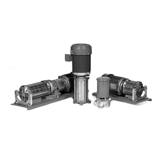
- Page 1 Section M50 • L50 Page 501 Dated October 2010 97-4624-01-588 M50 • L50 SERIES Pump Manual HORIZONTAL CLOSE COUPLED VERTICAL CLOSE COUPLED HORIZONTAL FLEXIBLE COUPLED...
-
Page 2: General Instructions
Page 502 M50 • L50 SERIES 1.General Instructions General Instructions HORIZONTAL CLOSE COUPLED For storage beyond 30 days, a 1D2 Construction Materials PUMPS corrosion inhibiting protective fl uid While it is reasonable to assume that VERTICAL CLOSE COUPLED PUMPS should be added to the internal pump good judgement has been used in HORIZONTAL FLEXIBLE COUPLED cavities. -
Page 3: Installation
Page 503 Valves in the outlet piping of a entrance velocity in the pump. If a then drain the inlet and outlet lines. regenerative turbine pump should pump requires more energy (or NPSH) Carefully blow out the pump with always be open as far as possible than is available at a given capacity, compressed air to clear all internal when the pump is started. - Page 4 Page 504 The fi rst consideration for locating 1/4” 1/4” a pump is elevation. The lowest Baseplate Finished Grouting Finished Grouting possible elevation using the shortest possible suction piping is usually 3/4” to 1 1/2” the best. Questions regarding Allowance for Allowance for Grout Grout...
-
Page 5: Operation
Page 505 around the periphery of the that no piping strains are causing coupling. DO NOT rotate the distortion. After approximately coupling. two weeks of operation, check the alignment again to make sure that If the maximum offset exceeds temperature changes, piping strain, the Parallel dimension in Chart 1 or foundation variations have not for your sleeve size, loosen the... - Page 6 Page 506 Rotation Inlet Outlet Rotation Inlet Inlet Inlet Outlet Outlet Outlet Outlet Figure 3-1 Figure 3-1 The pump inlet is located on the end than those required for installation. use the coupling on fl ex- nearest the motor, except on Model Because of the close fi...
- Page 7 Page 507 3G Priming Start the pump with the minimum Listen for indications of undue Pumps should not be operated possible line restriction. load or other sounds indicating unless they are completely fi lled problems. with liquid. Damage to parts of the Open discharge valves before pump that depend on liquid for their pressing the starter.
- Page 8 Page 508 attempt to remove the seal using a Place the motor bracket face screwdriver or other sharp object. down on a fl at surface. Extensive damage to the shaft, sleeve, or element could occur. Looking into the opening in the center of the bracket, you Before the motor bracket (#1) can will see a portion of the seat.
- Page 9 Page 509 To disassemble the pedestal: Check the shaft for galling, pitting, Refer to Figure 4-11 for reference to and corrosion. Surface corrosion on the numbered parts in the procedures Refer to Figure 4-28 for reference to the pump portion of the shaft must be below.
- Page 10 You may fi nd it easier to disassemble the pump further by standing the pump up on the motor end when there are fewer stages on the pump. For standard pumps (M50 Series), skip to step 16. 14. For inducer pumps (L50 Series), Figure 4-8 Insert the blades of the remove the Inducer Ring (#9IN).
- Page 11 It is recommended that a new rotating element be Using a soft mallet, loosen the For standard pumps (M50 Series), skip used for reassembly. DO NOT outlet cover (#2) by lightly tapping to step 16.
- Page 12 Page 512 Guide Rod “O”rings (#8) must be 25. Remove the guide rod nuts and 28. Disengage bearing lockwasher removed. guide rods from the endbell. tang from slot in the Bearing Locknut (#38), using a thin blade Gently tap on the back of 26.
- Page 13 Page 513 4E Inspection of Components be no smaller than .002” below the Install the motor bracket. nominal fractional seal sizes. Remove Thoroughly clean all parts. All any nicks or burrs which may have Make sure the Locking Collar components should be examined for occurred during disassembly.
- Page 14 Page 514 C30 - P30 CLOSE COUPLED PUMP QTY. PER PUMP USED KEY NO. NAME / DESCRIPTION Inlet Cover - Standard 1 IN Inlet Cover - Inducer Outlet Cover “O” Ring - Casing “O” Ring - Casing “O” Ring “O” Ring “O”...
- Page 15 Page 515 11 IN 1 - 1IN 110A L50 (Inducer) Stage L50 (Inducer) Stage P30 Bearing Pedestal 120 (Close Coupled) 33D (Bearing Frame) - Pipe Plug - Drain (Not Shown) - Pipe Plug - Drain (Not Shown) - Pipe Plug - Drain (Not Shown) - Pipe Plug - Drain (Not Shown) Figure 4-12 Figure 4-12...
- Page 16 Install the Shaft (#17) and Seal Install the guide rods. Thread the Rotating Element (#12) as a unit. For standard (M50 Series) pumps, skip four (4) Guide Rods (#18) into the to step 9. motor or bearing frame face. It...
- Page 17 Page 517 ring. You will need to stretch on fi rmly until the “O” ring fi ts Place an “O”Ring (#7) on the the “O” ring slightly to do so. inside the lip in the left hand raised step in the channel channel ring.
- Page 18 Page 518 19. Install the Outlet Cover Proceed to Section 4I Testing and Adjusting Nut (#110) into the Final Adjustments bore (this adjusting nut has a left Place an “O”Ring (#7) on hand thread). It is not necessary the raised step in the outlet 4H Reassembly Multistage on C30 to tighten the adjusting nuts cover.
- Page 19 The large inlet opening holder rests against the For standard (M50 Series) pumps, skip should be on the same side shoulder. Refer to Figure to step 14. as the pump inlet. Refer to 4-13.
- Page 20 Page 520 17. Slide an Interstage Bushing (#16) diagonally across the cover, until onto the shaft. The bushing Continue installing stages depending they are about one full turn short should be oriented such that the on how many stages are in the of being fully torqued.
- Page 21 Page 521 vented, prior to operation. DO be torqued to about 20 ft. lbs. to Using an amprobe or similar NOT RUN THE PUMP WITHOUT obtain proper performance. device, check for motor overload. FLUID. Check for leaks on pump and While the impeller is fi...
- Page 22 Page 522 Place the shaft with either bearing resting on top of the jaws and gently tap on the end of the shaft until the bearing is removed. Refer to Figure 4-23. I.D. 1” 1 5/16” - 1 1/2” O.D. 2”...
- Page 23 Page 523 and the shoulder of the shaft. Refer to Figure 4-27. Using extreme caution, gently tap on the end of the shaft until the bearing rests against the shoulder. Never attempt to install the bearings by striking the outer race.
- Page 24 Page 524 The following tools and equipment not necessary to tighten the Place Bearing Pedestal (#3) are needed for reassembly of P30 adjusting nuts completely until housing (with large opening units: the pump has been assembled down) over the end bell to the end bell, as some assembly.
-
Page 25: Troubleshooting
Page 525 the shaft. (Use a soft mallet so P30 Units: Look to make sure that the shaft surfaces are not damaged.) lip seals on the bearings are Check to be sure that the positioned properly in their No adjustments are possible rotating assembly turns freely. - Page 26 Page 526 suspicion of damage or wear, If there is a suspicion of damage, Pump locked up — Pump dried remove the pump from service remove the pump from service out and close clearance areas and disassemble for inspection. and disassemble for inspection. rusted.
-
Page 27: Parts And Repair Services
Page 527 follow reassembly instructions Pitted shaft under the seal — not a problem for the fi rst seal for seals. Seals on fl ex-coupled Reusing a shaft or sleeve when assembly since the elastomer is units can be damaged by repairing a pump is the probable conforming as this action occurs. -
Page 28: Limited Warranty
Section M50 • L50 Page 528 Dated October 2010 M50 • L50 SERIES 97-4624-01-588 7.Limited Warranty All requests for warranty claims by this Warranty. Warranty claims this Warranty by a purchaser shall be should be made through the com- for special order items or accessories for its own account and its exclusive pany from which the product was not manufactured by MTH (such as...
Need help?
Do you have a question about the M50 SERIES and is the answer not in the manual?
Questions and answers