Table of Contents
Advertisement
Advertisement
Table of Contents

Subscribe to Our Youtube Channel
Summary of Contents for Eco Spar AURIGA 23 kW
- Page 1 MANUAL for INSTALLATION and OPERATION of AURIGA 23 kW...
-
Page 2: Table Of Contents
Table of contents ....................1.0. PRECAUTIONS AND SAFETY ....................2.0. TECHNICAL CHARACTERISTICS .......................... 2.1 Accessories ....................2.2 Assembling the control panel ......................2.3 Technical description ....................2.4 Technical data and dimensions ........................3.0 INSTALLATION ........................3.1 GENERAL RULES ..................3.2 CONNECTION OF THE OUTER AIR PIPE ...................... -
Page 3: Precautions And Safety
Dear buyer, we thank you for choosing this product. This product is made with attention to all materials used and technologies employed. It was designed to satisfy your needs for a functional and safe product. By using this instruction manual you will learn how to use your pellet-burning stove properly; please read it carefully before use. -
Page 4: Technical Characteristics
Avoid direct contact with hot parts of the product. Check if there are difficulties while turning the product on after a long period of non- operation (see chapter 6.0). The pellet stove is designed to work even in extreme weather conditions, however, in case of strong wind or frosty conditions, the safety systems might trigger on and shut the pellet stove off. -
Page 5: Technical Description
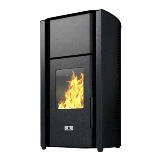
2.3 Technical description The AURIGA 23 kW is designed for heating residence or office spaces, as well as an additional heating, at the same time contributing to the more pleasant ambience. Suitable for central space heating. Mantle heat exchanger. The hearth of the pellet stove is made of very thick cold-rolled metal sheet, as well as a supporting structure which is coated with high temperature and high quality powder -like color. -
Page 6: Technical Data And Dimensions
2.4 Technical data and dimensions Model of the pellet stove: Height 1250 Width Depth Weight Diameter of air intake pipe Diameter of exhaust gas pipe Maximum heating (*) volume Nominal thermal power (Ptn) Decreased thermal power (Ptr) Nominal thermal power (water) Max. -
Page 7: Installation
3.0 INSTALLATION 3.1 General rules Knowing that the proper assembly is very important, as well as the proper connection of the exhaust gas system and that the possible errors made during the assembly are not covered by the warranty of MANUFACTURER , our company advices the installation to be made after the following checks: - Minimum volume of the space where the pellet stove is installed (avoid spaces smaller than 40m - Provide good air flow;... -
Page 8: Exhaust Gas System
For proper operation and proper distribution of the temperature, the pellet stove should have sufficient air intake and to be placed on suitable place (a special hole for air intake can be made). The hole for air intake should be 100 cm minimum and there should not be any obstacles. -
Page 9: Installation Schemes (Optional)
3.6 INSTALLATION SCHEMES (optional) 3.7 REAR END OF THE EXHAUST GAS PIPE The rear end of the exhaust gas pipe is intended for proper exhaust of the gases in the atmosphere, its protection against rain, snow or any other objects in order to guarantee excellent exhaust of the gases in windy conditions, as well. -
Page 10: Connection To The Electrical Power Supply
OPERATIONAL PROBLEMS DUE TO DEFECTS OF THE SYSTEM CAPACITY Besides all influencing atmosphere agents, the wind is the most important agent for the system operation 3.8 CONNECTION TO THE ELECTRICAL POWER SUPPLY The product should be connected to the electrical power supply. Our pellet stoves are supplied with a medium temperature persistent cable. -
Page 11: Installation
All specifications are listed below. Electrical power supply 230V, 50/60Hz, maximum consumption 13/20 mA. Inputs Exhaust gas temperature – Type J Outer thermostat - contact Probe NTC temperature room – NTC 10 k Outputs: Exhaust gas aspirator – 230 V Exchanger - 230 V Low-range gear lever –... - Page 12 RECOMMENDED SETTINGS FOR AURIGA 23KW 73. User fuel feeder 1 ON time factor --> 0. Fuel ignition timeout --> [20] 36. Power 3 fan 2 speed --> [0] [100] 1. Ignition test timeout --> [10] 37. Power 4 fan 2 speed --> [0] 74.
- Page 13 Using Fumis ALPHA keyboard Fumis ALPHA keyboard with remote control Figure 1: Fumis ALPHA keyboard and remote control The Fumis ALPHA capacitive touch keyboard is designed intuitively. It enables users at home to operate with the Fumis ALPHA controller. Note For best performance keep the keyboard clean.
-
Page 14: Menu Structure
selected menu context is indicated with the corresponding icon at the top. In addition, these buttons are used in the edit mode. Edit buttons (plus and minus buttons) are used for navigating the submenus and increasing/decreasing values in the edit mode, when the selected value blinks. Enter button is used for entering the edit mode and confirming the set values, or selecting the additional submenus. -
Page 15: Navigating The Menu
Note The Fumis ALPHA menu structure depends on the configuration and options. The menu structure in Figure 35 shows all possible menu entries. Depending on the selected configuration, some entries are not available. In such cases the menu entry is not included and submenus are renumbered accordingly. The display values are for representational purposes only and may differ from the actual display values. - Page 16 To view the current room temperature, press the menu button to enter the Temperature context menu. The current room temperature value is shown on the display. To set the desired room temperature, in the Temperature context menu press the Enter button. The display shows the set target temperature in the edit mode (the value is blinking).
- Page 17 desired room temperature for the selected time period. Confirm the program settings by pressing Enter. Repeat the procedure to set the programs. Example: Program 1 Program 2 Program 3 Program 4 Program 5 Program 6 5:30 7:30 8:00 11:30 12:00 23:00 17:00 23:00...
- Page 18 Program/Temperature setpoint P3 (22°C) P2 (21°C) P1 (20°C) time Heating device Heating device time LEGENDA: 7:00h (ON); 20:00h (OFF); temperature setpoint 20°C temperature setpoint in timer mode 9:00h (ON); 11:00h (OFF); temperature setpoint 21°C Heating device; 13:00h (ON); 17:00h (OFF); temperature setpoint 22°C Heating device Figure 3: Programs overlapping...
- Page 19 Modifying the setup options In the Setup menu context you can set the options for Key lock, Idle display brightness, Idle display mode, Beeper volume, Manual feed and view the Time to service (option, read only). To modify the setup options, press the menu button to enter the Setup context. To move between the setup options, press the edit buttons to display the settings.
- Page 20 Servicing Fumis ALPHA controller Basic servicing procedures of the Fumis ALPHA controller can be performed using the Fumis ALPHA keyboard. For additional options and advanced diagnostic procedures use the Fumis PC-PRO application. Unlocking the service menu To enable the service menu, in Fumis PC-PRO application configure the ServiceMenuKey (hidden parameter). If this parameter is set to 0, the service menu is not available in the Fumis ALPHA menu structure.
- Page 21 Service menu structure Setup Key lock . . . Service menu (unlocked) Parameters Parameter 1 Parameter 105 Parameter 0 Digital inputs Security PressureSwitch Digin11 Digin2 Motor rotations normal normal inverted inverted Analog Inputs Internal pressure NTC1 NTC2 NTC3 External analog sensor Digital outputs...
- Page 22 Modifying the parameters The Fumis ALPHA parameters are used to fine tune the operation of the combustion system with the Fumis ALPHA controller. Set the parameter values of the Fumis ALPHA controller, according to the selected configuration, to optimize the performance of the combustion system. With the Fumis ALPHA keyboard you can modify the parameter values, but you cannot change the valid parameter range settings.
- Page 23 Setting the Time to service notification Fumis ALPHA controller enables to set up the notification for regular maintenance. The Time to service shows when the regular service should be performed. It counts down in hours, and when this counter reaches zero, the Service icon starts blinking.
-
Page 24: Troubleshooting
Troubleshooting The Fumis ALPHA keyboard provides notifications and warnings for alerts and errors, which can occur when using the Fumis ALPHA controller. The alarm icons indicate a problem. An alert notification is indicated with the blinking icons, errors are indicated with continuously lit icons. In case of an alert, the combustion system is still operational, in case of an error the combustion system is seriously malfunctioning and the service personnel should be contacted. - Page 25 Solution: Contact the service personnel to change the Fumis ALPHA controller battery. Do not attempt to change the battery on your own. Fan 1 speed sensor failure Indication: Icon Service is blinking Code: A005 Cause: The fan 1 speed sensor malfunctioned. The combustion system is still operational. Solution: Contact the service personnel.
- Page 26 Service is required Indication: Icon Service is on Cause: The combustion system malfunctioned and is not operational. This can be due to: Code E001: Keyboard error Code E002: IR communication error Code E003: RF communication error Code E004: MB communication error ...
- Page 27 the Fire Up phase. More than 2minutes Fire Up phase The controller continues normally Burning phase The controller checks the flue gases temperature. If the flue gases temperature dropped below PAR56, the combustion system restarts in the Fire Up phase, otherwise it continues in the Burning phase.
- Page 28 Appendix A - Operation phases Operation Operation sequence Parameters phase PAR102 (anti-freeze temperature) Keep Fire PAR88 (feeder), PAR87, PAR89 (fan 1), PAR90 (repetition) FIRE UP Test Fire PAR20 (fan 1), PAR29 (fan 2), PAR40 (fan 3) Heat Up PAR3, PAR4 (feeder), PAR21 (fan 1), PAR31 (fan 2), PAR42 (fan 3), PAR70 (duration) Fuel ignition PAR0 (timeout), PAR5, PAR6 (feeder), PAR22 (fan 1),...
- Page 29 Appendix B - List of parameters Alarms Timeout Parameter Description Heat Up Timeout (Phase2) Ignition Timeout (in minutes): Maximum wait time for successful firing in the Ignition phase. Ignition Test Timeout Test Fire Timeout(in minutes): (Phase3) Maximum wait time for flame detection with igniter off in the Test Fire sequence.
- Page 30 Ignition Test Feeder 1 Ignition Test sequence feeder OFF time: OFF Time Defines the feeder pause during the Ignition Test sequence. Ignition Test Feeder 1 Ignition Test sequence feeder ON time: ON Time Defines the feeder dosing time during the Ignition Test sequence. Feeder: Burning Power 1 Feeder 1 OFF Power 1 feeder OFF time:...
- Page 31 Fan 1 Stop Fire Fan 1 Speed FAN1 speed in Fire Stop sequence: Defines the fan 1 speed during the Stop Fire sequence. Stop Fire is active when the heating device is turned OFF and flue gases are not cooled below PAR56. In BURNER configuration the Stop Fire runs until the Flame Sensor gives the NO FLAME signal (set with PAR79 and PAR80).
- Page 32 NOTE: Not used when advanced regulation is selected. Power 4 Fan 1 Speed FAN1 speed at power 4: Defines the FAN1 speed at power 4 (depends on the selected fan mode - open loop, closed speed loop or closed pressure loop). NOTE: Not used when advanced regulation is selected.
- Page 33 for each power PID regulator output. Maximum number of steps is 1024. NOTE: If the flue gases temperature is below PAR58 [⁰C] in FAN2 for Room Heating mode, FAN2 is switched off. Power 2 Fan 2 Speed FAN2 speed at power 2: NOTE: Not used when advanced regulation is selected.
- Page 34 Figure 6: Fan 3 operation Stop Fire Fan 3 Speed FAN3 speed in Stop Fire sequence NOTE: FAN3 operates in ON/OFF mode only. The valid settings for this parameter are 0 (FAN3 OFF) or 255 (FAN3 ON at maximum speed). You must also set the PAR77 and an air temperature sensor (NTC) must be connected to I/O T02.
- Page 35 Power 4 Fan 3 Speed FAN3 speed at power 4 NOTE: FAN3 operates in ON/OFF mode only. The valid settings for this parameter are 0 (FAN3 OFF) or 255 (FAN3 ON at maximum speed). You must also set the PAR77 and an air temperature sensor (NTC) must be connected to I/O T02.
- Page 36 Figure 9: Cool Fluid exit temperature settings for boilers and burners Parameter Description Cool Fluid Exit Temperature Cool Fluid exit temperature difference(in °C): Difference In Stove mode: the heating device restarts after room temperature drops below [PAR51-PAR50]. PAR50 is set in 0.1 degrees (10 equals 1.0°C), PAR51 is set in degrees (20 equals 20°C).
- Page 37 Cool Fluid when air temperature exceeds [PAR51 (in °C) +PAR53 (in 0.1°C)]. In Stove mode with water pump: The stop temperature based on the air temperature measurement is the same as above. The water stop temperature is defined with PAR95. In Boiler/Burner mode: this parameter defines the stop level in xx°C.
- Page 38 Value in UI Actual parameter value 400°C 400°C Fan 2 as Ambient Minimum FAN2 stop gases temperature (in °C): Gases Temperature If Fan 2 As Chimney is enabled, this parameter is ignored. If Fan 2 for Room Heating is enabled, this PAR defines the threshold for FAN2 operation, regardless of the operating sequence.
- Page 39 OFF Temperature / T1-T2 for Water pump turn off temperature (in °C): Max. Modul. Speed Defines the water pump turn off temperature threshold (MUST BE lower than PAR67 value). Anti-Condensation Exit Backwater temperature (in °C): Temperature Defines the backwater temperature threshold if a backwater temperature bypass pump is used.
- Page 40 External room temperatures Parameter Description 2nd Room Temperature External Room Temperature (in °C): Defines the external room temperature, regulated with FAN3. Figure 10: Fan 3 operation Flame sensors In the Burner configurations the flame sensor is used to detect flame in the burning chamber. Parameter Description Flame ON Level...
- Page 41 Airflow If this parameter is <>0, the underpressure/airflow error is enabled. If the underpressure in the burning chamber is lower than PAR82, the alarm is triggered after PAR83 seconds. Underpressure / Airflow Error Time delay before triggering underpressure/airflow error (in Delay seconds): Defines the time delay before the underpressure error is...
-
Page 42: Fuel Quality
Feeder 2 settings Feeder 2 is usually used for dosing secondary fuel or as pellets transporter from the main storage. It can also be used for mixing different fuels (pellets and olive stones, for example) in fixed proportions (%). For detailed description of feeder 2 operation refer to chapter Error! Reference source not found. on page Error! Bookmark not defined.. - Page 43 Defines the service due time. This parameter is used in connection with the Service time counter. PAR94 defines the service time period in days, but the Service time counter counts the hours. This means that if you set the PAR94=1 (day), the Service time counter displays 24 (hours).
-
Page 44: Pellets
Blow Out Duration Time for ash blow out at Stop Fire (in seconds): After the Stop Fire and Cool Fluid, the FAN1 will operate at maximum speed for PAR101 period. Anti-Freeze Temperature Minimum air temperature to keep (in °C): Only in stove mode and activated timer. OPERATION: The stove turns on when T (PAR 51 [⁰C]) is for 0,1⁰C lower than PAR 102 [0,1 x ⁰C]. -
Page 45: Pouring The Pellets
ATTENTION A clean system of exhaust gases is the guarantee for both the facility and the proper operation of Eco Spar products. It is important to clean the system on a regular basis. The exhaust gas system should be checked and cleaned when the pellet stove is turned on for the first time. - Page 46 - Inspection and possible replacement of the door rope; - Disassembling and cleaning of the T junction of the exhaust gas system; - Inspection of all electronic parameters; - Issue of a certificate for the completed inspection ATTENTION Do not clean the system until completely cooled down. Periodical cleaning of the OUTER SURFACE, GLASS, DOOR ROPE, ASH DRAWER Daily cleaning of the BURNER, EXCHANGER Monthly cleaning of the RESERVOIR...
- Page 47 PELLET RESERVOIR It is recommended to periodically clean the reservoir (at least once a month); firstly you should empty it and then clean it using a vacuum cleaner. GAS SYSTEM It is recommended to clean the general gas system once a year. To do it, it is necessary: - to open the door, to take out the ash tray After that, clean the system using a vacuum cleaner.
- Page 48 After cleaning, close the system. FRESH AIR INTAKE SYSTEM At the beginning of the heating season you should check the fresh air system, whether there is any obstacle in EXHAUST GAS SYSTEM At the beginning of the heating season you should clean the exhaust gas system. If the electrical cable is damaged, replace it.
Need help?
Do you have a question about the AURIGA 23 kW and is the answer not in the manual?
Questions and answers
Termomont toby b-17. Nav īsti saprašana kādiem cipariem būtu jābūt 1-5 līmeņu skalā 10 un 18 lodziņā tāpat ar 24 un 28 lodziņu.