Advertisement
CONTENTS
1. Safety information...............................
2. Description........................................
3. Operating instruction...........................
4. Specifications....................................
5. Battery & Fuse replacement..................
6. Accessory.........................................
1
5
7
13
17
19
Advertisement

Subscribe to Our Youtube Channel
Summary of Contents for S-line VA16
-
Page 1: Table Of Contents
CONTENTS 1. Safety information…………………………. 2. Description…………………………………. 3. Operating instruction……………………… 4. Specifications……………………………… 5. Battery & Fuse replacement………….….. 6. Accessory………………….………………. -
Page 2: Safety Information
1. SAFETY INFORMATION WARNING To ensure safe operation, and in order to exploit to the full functionality of the meter, please follow the directions in this section carefully. This multimeter has been designed according to IEC-1010 concerning electronic measuring instruments with an over voltage category Ⅱ... - Page 3 1.1.2 When the meter is delivered, check if it has been damaged in transit. 1.1.3 When harsh preservation or shipping conditions caused, inspect and confirm this meter without delay. 1.1.4 Test leads must be in good condition. Before using, verify that the insulation on test leads is not damaged and/or the leads wire is not exposed.
- Page 4 under test. 1.2.5 When carrying out measurements on TV or switching power circuits, always remember that there may be high amplitude voltages pulses at test points which can damage the meter. 1.2.6 Never perform resistance measurements on live circuits. 1.2.7 Always be careful when working with voltages above 60V dc or 30V ac rms.
- Page 5 disconnect test leads from all sources of electric current. 1.4.3 To avoid the wrong reading causing ”, electricity attack, when the meter displays“ you must change the battery. 1.4.4 For continue protection against fire, replace fuse only with the specified voltage and current ratings: F 200mA/250V (quick acting).
-
Page 6: Description
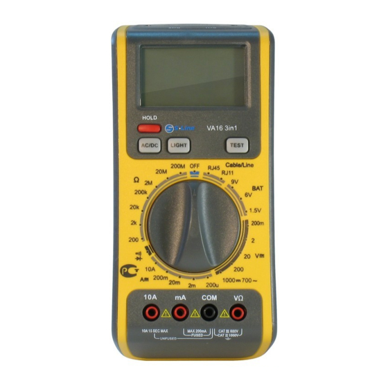
2. DESCRIPTION The 3 in 1 digital multi-tester has been designed to combine the functions of Digital Multimeter, Telephone Line Tester and Network Cable Tester. ● DC voltage measurement, 5 ranges from 200mV to 1000V ● AC voltage measurement, 5 ranges from 200mV to 700V ●... - Page 7 ○ 9 RJ45 jack(Remote) ○ 10 Function/range select rotary switch ○ 11 Cable test key/Resent ○ 12 Back light key ○ 13 LCD display - 6-...
-
Page 8: Operating Instruction
3. OPERATING INSTRUCTION 3.1 MEASURING VOLTAGE 3.1.1 Connect the black test lead to the COM jack and the red test lead to the V/Ω jack. 3.1.2 Set the rotary switch at the desired “V” range position and connect test leads across the source or load under measurement. - Page 9 position and connect test leads in series with the load under measurement. 3.2.3 Put down the "AC/DC" when measuring the current. Meter will be transformed between DC and AC range. 3.2.4 If you need data hold when measuring, you can put on “HOLD”, it will hold the reading; if you put the button again, data hold will not continue.
- Page 10 3.4 MEASURING RESISTANCE 3.4.1 Connect the black test lead to the COM jack and the red test lead to the V/Ω jack. ( NOTE :The polarity of red lead connection is positive“+”) 3.4.2 Set the rotary switch at desired Ω range position and connect test leads across the resistance under...
- Page 11 3.5 TESTING BATTERY 3.5.1 Connect the black test lead to the COM jack and the red test lead to the V/Ω jack. 3.5.2 Set the rotary switch at the desired “BAT” range position and connect test leads across the battery. Position 1.5v load...
- Page 12 condition in the above descending order before detecting other fault conditions. The detection and indication of the presence of a fault is handled on a “one-per-test” basis. Once a fault is corrected, it is recommended the cable be tested again for other faults.
- Page 13 Fig.1 SHORT Fig.2 MISWIRE Fig.3 REVERSED Fig.4 SPLIT PAIRS Fig.5 RIGHT (PASS) 3.7.1 Connect the RJ45 test jack to one end of the cable to be tested. 3.7.2 Connect the remote unit to the other end of the cable. 3.7.3 Push TEST button to perform test. Example: The Cable Fault is a SHORT on Pair 1-2 and Pair 3-6, the LCD status will be as follows: Pair 1-2, Pair 3-6, Pair 4-5, Pair 7-8, SHIE and...
-
Page 14: Specifications
4. SPECIFICATIONS Accuracy is specified for a period one year after calibration and at 18 ºC to 28 ºC ( 64 ºF to 82 ºF) with relative humidity to 80 %. 4.1 GENERAL MAXIMUM VOLTAGE 1000V DC or 700V AC FUSE PROTECTION mA: F 200mA/250V 10A: no POWER SUPPLY... - Page 15 AC VOLTAGE Range Resolution Accuracy ± 1.2 % of rdg ± 3digits 200mV 0.1mV ± 0.8 % of rdg ±3 digits 10mV 200V 100mV ± 1.2 % of rdg ± 5 digits 700V Input Impedance: 10MΩ Frequency Range: 40Hz to 400Hz (for AC) Response : Average, calibrated in rms of sine wave 4.3 CURRENT...
- Page 16 AC CURRENT Range Resolution Accuracy ±2.0 % of rdg ± 3 digits 200µA 0.1µA 1µA ±1.0 % of rdg ± 3 digits 20mA 10µA ±1.8 % of rdg ± 3 digits 200mA 100µA ±3.0 % of rdg ± 5digits 10mA Overload Protection: F 200mA/250V fuse for 200µA to 200mA ranges Frequency Range: 40Hz to 400Hz (for AC)
- Page 17 200MΩ range). Note: On 200MΩ range, if short input, display will read 1MΩ, this 1MΩ should be subtracted from measurement results. Overload Protection: 250V dc or 250V ac rms 4.5 DIODE/CONTINUTY Range Description Diode Shows the approximate forward voltage drop Built –...
-
Page 18: Battery & Fuse Replacement
5. BATTERY & FUSE REPLACEMENT ”appears on the LCD display, it If the sign“ indicates that battery should be replaced. Remove screws on the back cover and open the case (see the right photo). Replace the exhausted battery with a new one. Fuse rarely need replacement and blow almost always as a result of the operator’s error. - Page 19 WARNING Before attempting to open the case, be sure that test leads have been disconnected from measurement circuits to avoid electric shock hazard. For protection against fire, replace fuse only with specified ratings: F 200mA/250V - 18-...
- Page 20 6. ACCESSORIES • Test Leads: Electric Ratings one set 1000V 10A ‚ Battery: 9V, NEDA one piece 1604 or 6F22 ③ Operating Manual one piece - 19...
Need help?
Do you have a question about the VA16 and is the answer not in the manual?
Questions and answers