
Summary of Contents for Solid DMS-1200
- Page 1 ALLIANCE Release 6 DAS Management System DMS-1200 Operations Manual Version 1.3. ©February 2016. All Rights Reserved. Confidential & Proprietary. www.solid.com...
- Page 2 SOLiD reserves the right to change the contents without prior notice. In no event shall SOLiD be liable for any damages resulting from loss of data, loss of use or loss of profits. SOLiD further disclaims any and all liability for indirect, incidental, special, consequential or other similar damages. This disclaimer of liability applies to all products, publications and services during and after the warranty period.
- Page 3 To authorize technical support or to establish a return authorization for defective units, make sure you have the SOLiD serial numbers available. Serial numbers are located on the back of the unit, as well as on the box in which it was delivered. Contact SOLiD for additional support information: support@solid.com...
-
Page 4: Table Of Contents
6 System Alarm Setup ....................45 Monitoring Alarms and Viewing Troubleshooting Tips ............... 46 Customizing Alarms ........................48 7 DAS Device Control ....................50 Using the Device Control Screens ....................51 Version 1.3. ©February 2016. All Rights Reserved. Confidential & Proprietary. www.solid.com... - Page 5 Viewing Trend Information ......................93 Monitoring System Event Logs ....................95 Viewing the System Inventory ....................97 10 SNMP Trap IDs and Alarm Descriptions ..............98 11 Glossary ........................ 101 Version 1.3. ©February 2016. All Rights Reserved. Confidential & Proprietary. www.solid.com...
-
Page 6: Dms-1200 Release 6 Overview
DMS-1200 Release 6 Operations Manual DMS-1200 Release 6 Overview The DMS-1200 REL6 is a DAS management system that provides an alarming, diagnostic, and control interface for one or more SOLiD ALLIANCE DAS platforms. The DMS-1200 provides these management functions for the DAS network: •... - Page 7 Remotely from an external NOC through the public Internet by connecting the DMS-1200 to your data network. The DMS-1200 server is based on the Ubuntu 12.04 LTS operating system. You can view the user interface in any standard web browser from a desktop or laptop computer. A Gigabit Ethernet switch is used when connecting multiple BIUs.
-
Page 8: Dms-1200 Specifications
DMS-1200 Release 6 Operations Manual DMS-1200 Specifications The DMS-1200 server is typically mounted in the head end rack above the ODUs and in close proximity to the BIUs. The server has an internal power supply and requires standard 120-240V AC power. A power cable ships with the unit. -
Page 9: Standards, Certifications And Emc Approvals
Do not use any solvents, chemicals, or cleaning solutions containing alcohol, ammonia, or abrasives on the DMS-1200 equipment. FOR EMERGENCY SHUTOFF INSTRUCTIONS SEE PAGE 23. 1.1.3 PC Requirements To view the DMS-1200 user interface, you can use any standard laptop or desktop computer with these minimum specifications. Type Specification Hardware At least one Ethernet Port. -
Page 10: Dms-1200 Front / Rear Panel
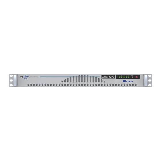
DMS-1200 Release 6 Operations Manual DMS-1200 Front / Rear Panel Figure 1.3 – DMS-1200 Front Panel View LED / Button Description Green indicates DMS operating within normal temperature range. Red 1. System Overheat indicates DMS internal temperature exceeds normal range. -
Page 11: Quick Start
DMS-1200 Release 6 Operations Manual Quick Start Several of the DMS-1200 features will be used for initial setup of the DMS and DAS, while others are used for ongoing maintenance. Links to common tasks are shown in the following tables:... -
Page 12: Hardware Installation
ODUs and in close proximity to the BIUs. The server has an internal power supply and requires standard 120-240V AC power. A power cable ships with the unit. The DMS-1200 server requires 1U in a standard 19-inch equipment rack but should have 1U above and below for air circulation. -
Page 13: Required Materials
Table 2.1 – Tools and Accessories for Installing DMS Equipment Installing the DMS Hardware 1. Using the rack mount brackets, install the DMS-1200 in the rack, making sure to leave 1U of space above and below the DMS and other DAS components. This gap provides air circulation to help dissipate heat from the equipment. -
Page 14: Connecting The Dms-1200 To The Das
2. Connect the other end into the Ethernet Port located on the front of the Main Central Processor Unit (MCPU) at the front of the BIU. The DMS will automatically assign an IP address to the BIU. Figure 2.1 – DMS-1200 to BIU Connection Section 2 – Hardware Installation... -
Page 15: Connecting Multiple Bius To The Dms-1200
Ethernet port and Automatic DHCP is enabled in your PC’s network settings. 2. Remote setup: To setup the DMS-1200 for remote login from an external NOC, connect one end of an Ethernet cable into the WAN port on the back of the DMS-1200. Connect the other end to your data network. -
Page 16: Login And Biu Assignment
DMS-1200 Release 6 Operations Manual Login and BIU Assignment You can log in to the DMS-1200 either while onsite or from an offsite location like a Network Operations Center (NOC). Before you can use the DMS-1200 to manage the DAS, you will need to register or “assign” each BIU in the system. -
Page 17: Logging In
IP address: 192.168.58.1 TIP: To set up a secure session (SSL), use https:// before the URL or IP address. b. If logging in remotely: open your web browser and enter the DMS-1200’s Outside IP Address. (See the section Setting the DMS IP Address on page 28.) -
Page 18: Assigning Bius
DMS-1200 Release 6 Operations Manual Assigning BIUs When you connect the DMS to the DAS, the DMS should automatically recognize the system’s BIUs and load BIU information to the Unassigned BIU list. From there, you will need to add the system’s BIUs to the Assigned BIU list before you can manage them using the DMS. -
Page 19: Viewing Remote Access Settings
DMS-1200 Release 6 Operations Manual b. If the BIU does not appear on the list, click Add. Enter the BIU IP address, then click Apply. 3. Check the communication Status. Green indicates a working connection is established. The system populates the BIU Name and Serial Number fields. -
Page 20: Using The Main Screen
DMS-1200 Release 6 Operations Manual Using the Main Screen The Main screen shows the current status of the DMS and provides access to the Navigation Bar menus and submenus. 3.3.1 System Status You can view the current DAS status, topology, alarm conditions and DMS connection status from the options at the top of the Navigation Bar. -
Page 21: System Topology View
DMS-1200 Release 6 Operations Manual 3.3.2 System Topology View Topology View shows the system hierarchy in graphical form and provides quick access to the Control screens for each device. 1. Click Topology to display the system hierarchy and current alarm status in graphical form. - Page 22 DMS-1200 Release 6 Operations Manual 4. Use the other features on the Topology screen according to these guidelines: The Backup feature creates an internal backup file of all operating settings for the BIU and the DAS components connected to that BIU.
-
Page 23: Emergency Shut-Off Function
3.3.3 Emergency Shut-off Function The Administrator can turn off all amplifiers in the remote units by clicking the Emergency button in the DMS-1200 main screen. For systems with multiple BIUs, the Administrator can turn off remotes on a per BIU basis. - Page 24 DMS-1200 Release 6 Operations Manual To turn on remotes: If the Emergency Shutoff screen is not showing, click the Emergency button. 4. To turn on amplifiers, either click on individual BIUs to turn on remotes just connected to that BIU, or click TURN ON ALL to turn on all remotes in the system.
-
Page 25: Navigation Bar Menus
DMS-1200 Release 6 Operations Manual 3.3.4 Navigation Bar Menus The menus on the Navigation Bar are used to set up and manage the DMS and DAS components. Navigation Bar Sub Menu Action / Status Manage DAS site information (location, installation Site Info contractor, technical support contact). -
Page 26: Dms-1200 Setup
DMS-1200 Release 6 Operations Manual DMS-1200 Setup This section provides instructions on using the Site Info and Network menus to set up the DMS- 1200 and network interfaces. In This Section Editing Site Info Setting the DMS IP Addresses Setting System Time... -
Page 27: Editing Site Info
DMS-1200 Release 6 Operations Manual Editing Site Info 1. On the Navigation Bar, click Site Info. 2. Edit Site Info details according to the following guidelines: Picture Option Action Site Name / Site Address Specify the location of the DAS site. -
Page 28: Setting The Dms Ip Addresses
Enter the Outside Subnet Mask address. Outside Gateway Enter the Outside Gateway address. Enter the internal IP address of the DMS-1200 server. This is the IP Inside IP Address address for the BIU port at the back of DMS-1200. Inside Subnet Mask Enter the Inside Subnet Mask. -
Page 29: Setting System Time
DMS-1200 Release 6 Operations Manual Setting System Time You can manually set the system time or use a Network Time Protocol (NTP) service. 1. On the Network menu, click System. 2. Edit the Time settings according to the following guidelines:... -
Page 30: Managing The Event Log
Managing the Event Log Using the Event Log settings, you can define how often the alarm and status logs are cleared. The DMS-1200 offers manual and auto modes. 1. On the Network menu, click System. 2. Edit the Event Log settings according to the following guidelines:... -
Page 31: Managing The Trend Log
DMS-1200 Release 6 Operations Manual Managing the Trend Log Use the Trend Log settings to manually delete all trend log data or setup an auto deletion routine. 1. On the Network menu, click System. 2. Edit the Trend Log settings according to the following guidelines:... -
Page 32: Scheduling The System Backup
DMS-1200 Release 6 Operations Manual Scheduling the System Backup Use the Scheduling Backup settings to turn on/off auto backup and set schedule and retention times. 1. On the Network menu, click System. 2. Edit the Scheduling Backup settings according to the following guidelines:... -
Page 33: Upgrading Dms Software
Upgrading DMS Software Periodic software upgrades are available for the DMS-1200 server. Contact SOLiD Support details. (You can also upgrade firmware for the DAS components using the DMS-1200. See the section Upgrading Firmware for DAS Components starting on page 83.) 1. -
Page 34: Rebooting The Dms Server
BIUs and load BIU information to the Unassigned BIU list. You will need to move unassigned BIUs to the Assigned BIU list before you can manage the BIU using the DMS-1200. If a connected BIU is not automatically recognized by the DMS, you can also manually add it to the Assigned BIU list. - Page 35 DMS-1200 Release 6 Operations Manual b. If the BIU does not appear on the Unassigned list, click Add. Enter the BIU IP address. Then click Apply. 3. Check the communication Status. Green indicates a working connection is established. The system populates the BIU Name and Serial Number fields.
-
Page 36: Managing Noc And Snmp Settings
Network Operation Center (NOC). 4.10.1 Set the SNMP Heartbeat The Heartbeat is a periodic message that notifies the NOC that the DMS-1200 is online and operational. When the Heartbeat feature is enabled, the DMS-1200 will send a message to the NOC according to the Heartbeat time interval. -
Page 37: Set The Snmp V2 Community And Trap Manager
To support SNMP v2, you will need to configure the Community and Trap manager. The SNMP community text string is like a user ID or password that allows access to an SNMP agent. The Trap manager receives traps from the DMS-1200, for example at the NOC. 1. On the Network menu, click NOC Setup. -
Page 38: Set The Snmp V3 User And Trap Session
DMS-1200 Release 6 Operations Manual 4.10.3 Set the SNMP v3 User and Trap Session SNMP v3 provides secure access to devices by authenticating and encrypting packets over the network. To support SNMP v3, first configure user and trap session information. - Page 39 DMS-1200 Release 6 Operations Manual 3. In the SNMP Trap Session section, edit the settings according to these guidelines. Column Action / Status Specify IP address of a trap session, for example: 192.168.0.16 User Specify a User name. Manager Name Enter a descriptive name of the trap session.
-
Page 40: Setting Up Email Notification
DMS-1200 Release 6 Operations Manual 4.11 Setting up Email Notification The DMS-1200 can send emails to administrators or technicians to notify them of alarm conditions. You can customize the email notifications to report alarms according to the severity level. For example, some administrators may only want to be notified of “critical” alarms, while others may want to see all alarms reported by the system. -
Page 41: Managing Email Server Settings
DMS-1200 Release 6 Operations Manual 4.12 Managing Email Server Settings For the DMS-1200 to send emails, you must first define settings for the email server on your network. 1. On the Network menu, click Email. 2. Click the SMTP Server tab. -
Page 42: User Account Setup
In This Section Adding / Deleting User Accounts Viewing Active Users Related Topics Email Notification: The DMS-1200 can send emails to system users (like administrators or technicians) to notify them of alarm conditions. (See the Setting up Email Notification section.) -
Page 43: Adding / Deleting User Accounts
Only Administrators can add or delete user accounts. 1. On the Management menu, click User Management. 2. Click the User tab to see a list of all registered users of the DMS-1200. 3. To add a user, click Add. 4. In the Add User dialog box, enter the user information. Fields with an asterisk (*) are required. -
Page 44: Viewing Active Users
DMS-1200 Release 6 Operations Manual 5. Click Apply when you are done adding user information. 6. To edit information for a user, like changing the password, click the Edit icon. 7. To delete a user, click Remove next to the user name. This action cannot be undone. -
Page 45: System Alarm Setup
Error conditions that produce Alarms for system components – like the BIU, MDBU, DOU, etc. – are pre-defined at the SOLiD factory. The Alarm menus allow you to view active alarms for these components, customize how they are reported, and see troubleshooting tips for resolving them. -
Page 46: Monitoring Alarms And Viewing Troubleshooting Tips
DMS-1200 Release 6 Operations Manual Monitoring Alarms and Viewing Troubleshooting Tips 1. On the Management menu, click Active Alarm. 2. Click Refresh. Using the drop-down lists at the top of the Active Alarm screen, filter the alarm list using any of the following criteria:... - Page 47 DMS-1200 Release 6 Operations Manual You can also filter by any Keyword in the Name and Alarm fields: place your cursor over the text in the field. Then click on the text to see the Input Keyword dialog box. Enter a search keyword then click OK to filter by that keyword.
-
Page 48: Customizing Alarms
Mask For a masked alarm, the DMS-1200 will not generate an SNMP trap, but it will continue to report the status of this device in its Alarm lists and Event log. - Page 49 DMS-1200 Release 6 Operations Manual 5. To customize Alarm Levels, click on the Alarm Level tab. 6. Edit the label text, if desired, and associate a color for each Alarm Level that will be used for all Alarm reporting. 7. Click Apply when you are done.
-
Page 50: Das Device Control
DMS-1200 Release 6 Operations Manual DAS Device Control The DMS-1200 supports several functions for monitoring and controlling the DAS devices: • Initial System Commissioning – The initial system commissioning process comes after hardware installation and prepares the DAS to handle live network traffic. Two methods... -
Page 51: Using The Device Control Screens
DMS-1200 Release 6 Operations Manual Using the Device Control Screens 1. From the Control menu, click Command. 2. Select the target device from the Tree Menu or the Menu Bar drop-down lists to load its control screen. The status for each device is shown in one of three states: Green = Device is operating normally. -
Page 52: Setting Biu Parameters
DMS-1200 Release 6 Operations Manual Setting BIU Parameters The BIU Control screen allows you to monitor and manage settings for the individual BIU, MDBUs, VHF/UHF services, and External Alarms. 7.2.1 BIU Setup 1. In the Tree Menu or Menu bar, click on the BIU to load its Control screen. -
Page 53: Mdbu, Vhf / Uhf Setup
You can see the Min / Max values for the parameter by clicking in the field. TIP: SOLiD’s recommended device settings can be found in the document: ALLIANCE DAS Tech Note - Commissioning with DMS-1200 available from SOLiD support. 2. Configure TX and RX settings for the MDBU according to the guidelines in the following... - Page 54 DMS-1200 Release 6 Operations Manual User MDBU Field Description Configure Tx PLL Lock Tx Phase Locked Loop status. Green = Normal (locked). Red = PLL unlocked. (Not applicable to VHF/UHF setup.) Tx In Power Shows Tx input power on that port (±2dB) and status: Green = within high/low limits.
-
Page 55: External Alarm Setup (Optional)
DMS-1200 Release 6 Operations Manual 7.2.3 External Alarm Setup (Optional) Three dry contacts are located at the BIU back panel that can be used to support external alarms for reporting conditions like a module failure, high temperature condition or power failure. These alarms can be connected to the auxiliary input of the Base station or any other dry-contact application. - Page 56 DMS-1200 Release 6 Operations Manual To Activate Alarms for Dry Contacts 1. From the MDBU Control screen, click the External Alarm tab. 2. Check the External ALM Enable box if you want to activate contacts #1, #2, and/or #3. 3. For each enabled contact, check the Enable box for each condition you would like reported.
-
Page 57: Setting Odu Parameters
DMS-1200 Release 6 Operations Manual Setting ODU Parameters The ODU Control screen allows you to monitor and manage settings for the ODU and the Donor Optic Units (DOUs) in the ODU. 7.3.1 ODU / DOU Setup 1. In the Tree Menu or Menu bar, click the ODU you want to configure to load its control screen. -
Page 58: Setting Oeu Parameters
DMS-1200 Release 6 Operations Manual Setting OEU Parameters The Optical Expansion Unit (OEU) has two types of optical modules: E-Optic module for connecting the OEU to the ODU, and up to two DOUs for connecting to ROUs. The DOUs used in the OEU are the same units used in the ODU and have the same configuration options. - Page 59 DMS-1200 Release 6 Operations Manual E-Optic Field Action / Description User Configure LD Power Displays current laser diode power of E-Optic module. Green = normal. Red = power is below reference power current. PD Power Displays current photo diode power received from ROU or OEU.
- Page 60 DMS-1200 Release 6 Operations Manual The OEU Control screen also includes the configuration fields for the DOUs installed in the OEU. Each DOU has four ports. Active ports are lit in blue; inactive are greyed. 3. Configure each active port on the DOUs according to these guidelines:...
-
Page 61: Setting Remote Optic Unit (Rou) Parameters
TIP: SOLiD’s recommended settings for all remote units and drive units can be found in the document: ALLIANCE DAS Tech Note - Commissioning with DMS-1200 available from SOLiD support. -
Page 62: Lrou Setup
DMS-1200 Release 6 Operations Manual 7.5.1 LROU Setup This section describes how to set up the low-power (1W) remote optic unit (LROU). 1. In the Tree Menu or Menu bar, click on the LROU to configure. In the LROU setup screens, some fields show current settings and are not user configurable. - Page 63 DMS-1200 Release 6 Operations Manual 3. Configure the Optic Information according to the guidelines in following table: User ROU Field Action / Description Configure LD Power Shows laser diode power of R-Optic module. Green = normal. Red = Power is below reference power.
-
Page 64: Lrdu Setup
DMS-1200 Release 6 Operations Manual 7.5.2 LRDU Setup This section describes how to set up the low-power remote drive units (LRDUs) located in the LROU or the Add-On Unit (AOR). In the Tree Menu or Menu bar, click on the LROU or AOR that contains the RDUs you want to configure. - Page 65 DMS-1200 Release 6 Operations Manual 3. Configure the RX settings according to the following guidelines: User Field Action / Description Configure RX Values Rx PLL Lock Rx Phase Locked Loop status. Green = normal. Red = PLL unlocked. Rx In Power Shows Rx input power on that port (±2dB).
-
Page 66: Mrou Setup
DMS-1200 Release 6 Operations Manual 7.5.3 MROU Setup This section describes how to set up the mid-power remote unit (MROU). 1. In the Tree Menu or Menu bar, click on the MROU to configure. In the MROU setup screens, some fields show current settings and are not user configurable. - Page 67 DMS-1200 Release 6 Operations Manual 3. Configure the Optic Information according to the guidelines in following table: User ROU Field Action / Description Configure LD Power Shows laser diode power of R-Optic module. Green = normal operation. Red = Power is below reference power.
-
Page 68: Mrdu Setup
DMS-1200 Release 6 Operations Manual 7.5.4 MRDU Setup This section describes how to set up the mid-power remote drive units (MRDUs) installed in the MROU or the Add-On Unit (AOR). 1. In the Tree Menu or Menu bar, click on the MROU or AOR that contains the RDUs you want to configure. - Page 69 DMS-1200 Release 6 Operations Manual 3. Configure the RX settings according to these guidelines: User Field Action / Description Configure RX Values Rx PLL Lock Rx Phase Locked Loop status. Green = normal. Red = PLL unlocked. Rx In Power Shows Rx input power on that port (±2dB).
-
Page 70: Hrou (Titan) Setup
TIP: SOLiD’s recommended device settings can be found in the document: ALLIANCE DAS Tech Note - Commissioning with DMS-1200 available from SOLiD support. 2. Configure the System Information according to the following guidelines: Section 7 – DAS Device Control... - Page 71 DMS-1200 Release 6 Operations Manual User HROU Field Action / Description Configure ROU Name Enter a name to be used to Identify ROU throughout the system. Maximum 40 alpha-numeric characters. F/W Version Firmware version of the ROU CPU. Temperature Current temperature of ROU. Also shows temperature alarm status.
- Page 72 DMS-1200 Release 6 Operations Manual 3. Configure the Optic Information according to these guidelines: User HROU Field Action / Description Configure LD Power Shows laser diode power of R-Optic module. Green = normal. Red = Power is below reference power.
-
Page 73: Hrdu (Titan) Setup
DMS-1200 Release 6 Operations Manual 7.5.6 HRDU (TiTAN) Setup This section describes how to set up the high-power remote drive units for the TiTAN main units (HMRU) and add-on units (HARU). 1. In the Tree Menu or Menu bar, click on the HMRU or HARU that contains the drive units you want to configure. - Page 74 DMS-1200 Release 6 Operations Manual 3. Configure the RX Values for the drive unit according to these guidelines: User Field Action / Description Configure RX Values Rx PLL Lock Rx Phase Locked Loop status. Green = Normal. Red = PLL unlocked.
- Page 75 DMS-1200 Release 6 Operations Manual 4. Configure settings for the fan units according to these guidelines. User Field Action / Description Configure FAN (Insert) Shows status of fan. Green = normal operation. Red = fan is not functioning. FAN Enable Click the toggle to turn fan unit On/Off.
-
Page 76: Nhrou (Thor) Setup
DMS-1200 Release 6 Operations Manual 7.5.7 NHROU (THOR) Setup This section describes how to set up the THOR high-power remote optic unit (NHROU). 1. In the Tree Menu or Menu bar, click on the NHROU to configure. In the setup screens, some fields show current settings and are not user configurable. Other fields allow you to configure parameters for the device. - Page 77 DMS-1200 Release 6 Operations Manual 3. Configure the Optic Information according to these guidelines: User ROU Field Action / Description Configure LD Power Shows laser diode power of R-Optic module. Green = normal operation. Red = Power is below reference power.
-
Page 78: Green Mode Setup (Thor Nhrou Only)
DMS-1200 Release 6 Operations Manual 7.5.8 Green Mode Setup (THOR NHROU Only) The 20W (THOR) NHROU offers a “Green Mode” setting, which can reduce the remote’s power consumption. Green Mode can be activated by either time of day, TX power levels or both conditions. -
Page 79: Nhrdu (Thor) Setup
DMS-1200 Release 6 Operations Manual 7.5.9 NHRDU (THOR) Setup This section describes how to set up the high-power remote drive units (HRDUs). From the HRDU configuration screens, you can change settings for remote drive units in the HROU and for the external alarm feature. - Page 80 DMS-1200 Release 6 Operations Manual 3. Configure the RX settings according to these guidelines: User Field Action / Description Configure RX Values Rx PLL Lock Rx Phase Locked Loop status. Green = normal. Red = PLL unlocked. Rx In Power Shows Rx input power on that port (±2dB).
-
Page 81: Pimd Level Measurement (Thor Nhrou Only)
DMS-1200 Release 6 Operations Manual 7.5.10 PIMD Level Measurement (THOR NHROU Only) The 20W NHROU can measure passive intermodulation (PIMD), a form of intermodulation distortion that can occur in passive components like antenna ports, coaxial connectors and cables. Excessive PIMD can reduce the receive sensitivity of the DAS affecting the system’s reliability, capacity and data rate. -
Page 82: External Alarm Setup (Thor Nhrou Only)
DMS-1200 Release 6 Operations Manual 7.5.11 External Alarm Setup (THOR NHROU Only) The NHROU supports an External dry contact alarm feature for both output and input alarms. Output alarms can be sent to any dry contact application. External ALM #1 supports output alarms. An event indicates active output on the alarm. -
Page 83: Upgrading Firmware For Das Components
Update firmware for all system components from the Control > Firmware Download menu. 1. Obtain the latest firmware files from SOLiD Support. Load the firmware on your PC. 2. On the Control menu, click Firmware Download. 3. Click Choose File. Select the firmware file from your PC’s file directory and click Open from the Windows dialog box to confirm. -
Page 84: Backing Up And Restoring Device Settings
DMS-1200 Release 6 Operations Manual Backing up and Restoring Device Settings You can save DAS operational settings in a backup file and restore the settings as needed. You can also download a report in spreadsheet format showing current settings for each DAS device. -
Page 85: Restore Settings
DMS-1200 Release 6 Operations Manual 7.7.2 Restore Settings 1. To restore backups of DAS control settings, click Restore from the Device Control screen. 2. From the dialog box, check the Use box for the backup file to use. 3. Click Run. -
Page 86: System Commissioning With Easyset
DMS-1200 Release 6 Operations Manual System Commissioning with EasySet EasySet is SOLiD’s quick commissioning solution that supports these functions: • Auto Setup –set up all automatic functions (i.e., Auto Level Control, Auto Gain Control, Auto Gain Setting) at one time from a single screen. -
Page 87: Commissioning The Das
DMS-1200 Release 6 Operations Manual Commissioning the DAS The Auto Setup function provides a single screen for setting up all automatic functions in the DAS (i.e., Auto Level Control, Auto Gain Control, Auto Gain Setting). The Commissioning function optimizes all system parameters to the user-defined levels set in the Auto Setup process. When... - Page 88 DMS-1200 Release 6 Operations Manual 4. Adjust TX Input and RX Output settings as desired. The following tables offer guidelines for each setting as well as SOLiD recommendations. You can see the Min / Max values for the parameter by clicking in the field.
- Page 89 DMS-1200 Release 6 Operations Manual ROU / RDU User Configuration SOLiD Fields Recommendation Turn On. Set to max On/Off toggle for Auto Limit Control. When On, system TX Output power output for that will apply attenuation when this value is met or...
-
Page 90: Running Auto Setup Without System Commissioning
DMS-1200 Release 6 Operations Manual Running Auto Setup without System Commissioning When executing EasySet with System Commissioning, all parameters are optimized and the system performs PIMD measurement. This process can take a few minutes, and during this time call drops in the DAS could occur. -
Page 91: Calculating Power Distribution
DMS-1200 Release 6 Operations Manual Calculating Power Distribution The Power Distribution function automatically calculates the attenuation level required to equally distribute TX power levels according to the number of channels and the type of input signal (i.e., 700LTE, 1900, AWS, etc.). For dual BIU configurations, this function will allocate the same amount of power to each band in both the primary and secondary BIU. -
Page 92: Restoring Factory Defaults
DMS-1200 Release 6 Operations Manual Restoring Factory Defaults This function resets the parameters for the MDBUs and Remote Units to factory defaults. Factory Set applies to all BIUs and associated remotes in the DAS. 1. Click Factory Set and OK to confirm. -
Page 93: Trend Data, Event Logs And System Inventory
DMS-1200 Release 6 Operations Manual Trend Data, Event Logs and System Inventory Viewing Trend Information Trend data is available from the Control > Trend menu to monitor performance of DAS devices. 1. On the Control menu, click Trend. 2. From the Tree Menu, select the device. - Page 94 DMS-1200 Release 6 Operations Manual 3. From the Type drop-down list, select the trend you want to see in the graph. These will vary according to the Device. 4. From the Period drop-down list, select the time interval to be used in the graphs X axis – 15 minute or 1 day intervals.
-
Page 95: Monitoring System Event Logs
DMS-1200 Release 6 Operations Manual Monitoring System Event Logs The Event Log shows alarm, control, and security events. 1. On the Navigation Bar, click Event Log. 2. Filter the log as desired. Two methods are available. a. Using the drop-down lists at the top of the window, filter the log according to these guidelines. - Page 96 DMS-1200 Release 6 Operations Manual b. To filter by any Keyword in the Name and Message fields, place the cursor over the text in the field. Then click on the text to see the Input keyword dialog box. Click OK to filter.
-
Page 97: Viewing The System Inventory
DMS-1200 Release 6 Operations Manual Viewing the System Inventory The Inventory screen shows all currently connected DAS network components. You can print the inventory and download a file in spreadsheet format. 1. On the Navigation Bar, click Inventory. 2. From the BIU drop down list, select a specific BIU or All to show the inventory for all BIUs connected to the DMS-1200. -
Page 98: Snmp Trap Ids And Alarm Descriptions
(MIB) files provided for SNMP traps and object identifiers (OID). These are used by the DMS-1200 to manage components on the DAS network. Suggested Priority Levels and Hysteresis are shown for each alarm. TIP: All Trap Names start with “dms1200REL6Alarm” and all the Object IDs start with 1.3.6.1.4.1.35043.1.1.1201. - Page 99 DMS-1200 Release 6 Operations Manual Object ID (OID): 1.3.6.1.4.1.35043.1.1.1201. Trap Name: dms1200REL6Alarm Suggested Suggested Trap Name End Description Priority Level Hysteresis (seconds) 4.25 OeuOpticCompFail Major (4) TX Optic Compensation Fail 4.26 OeuLinkFail Major (4) Link Failure 4.27 LrouHighTemp Major (4) High Temperature Alarm 4.28...
- Page 100 DMS-1200 Release 6 Operations Manual Object ID (OID): 1.3.6.1.4.1.35043.1.1.1201. Trap Name: dms1200REL6Alarm Suggested Suggested Trap Name End Description Priority Level Hysteresis (seconds) 4.60 HrouBatteryLow Critical (5) Battery Low Alarm 4.61 HrouDoorOpen Minor (3) Door Open 4.62 HrouFanFail Major (4) Fan Failure 4.63...
-
Page 101: Glossary
Optic Distribution Unit. The ODU converts the R F signal to an optical signal and transmits it via fiber to the ROU. Optic Expansion Unit. The unit in the SOLiD DAS topology that expands a DAS to include multiple buildings and structures using only one strand of fiber. - Page 102 DMS-1200 Release 6 Operations Manual SMTP Simple Mail Transfer Protocol SNMP Simple Network Management Protocol. An IP based protocol for managing devices on an IP network. Secure Sockets Layer. A protocol for encrypting and transmitting private data via the Internet.
Need help?
Do you have a question about the DMS-1200 and is the answer not in the manual?
Questions and answers