Yamaha EZ-EG Service Manual
Hide thumbs
Also See for EZ-EG:
- Owner's manual (2 pages) ,
- Short manual (2 pages) ,
- Supplementary manual (3 pages)
Table of Contents
Advertisement
SERVICE MANUAL
本资料由OKXIA视听皮带资源库www.okxia.cn提供
CONTENTS
SPECIFICATIONS ··································································· 3
PANEL LAYOUT ······································································· 4
CIRCUIT BOARD LAYOUT ······················································ 5
BLOCK DIAGRAM ··································································· 6
DISASSEMBLY PROCEDURE ················································ 7
LSI PIN DESCRIPTION ··························································· 9
IC BLOCK DIAGRAM ···························································· 11
CIRCUIT BOARDS ································································ 12
TEST PROGRAM ·································································· 16
INSPECTIONS ······································································· 18
MIDI IMPLEMENTATION CHART ·········································· 19
PARTS LIST
OVERALL CIRCUIT DIAGRAM
PK
011675
HAMAMATSU, JAPAN
Copyright (c) Yamaha Corporation. All rights reserved. PDF-K724
'03.02
Advertisement
Table of Contents

Related Manuals for Yamaha EZ-EG


Summary of Contents for Yamaha EZ-EG
- Page 1 LSI PIN DESCRIPTION ··························································· 9 IC BLOCK DIAGRAM ···························································· 11 CIRCUIT BOARDS ································································ 12 TEST PROGRAM ·································································· 16 INSPECTIONS ······································································· 18 MIDI IMPLEMENTATION CHART ·········································· 19 PARTS LIST OVERALL CIRCUIT DIAGRAM 011675 HAMAMATSU, JAPAN Copyright (c) Yamaha Corporation. All rights reserved. PDF-K724 '03.02...
- Page 2 IMPORTANT NOTICE This manual has been provided for the use of authorized Yamaha Retailers and their service personnel. It has been assumed that basic service procedures inherent to the industry, and more specifically Yamaha Products, are already known and understood by the users, and have therefore not been restated.
-
Page 3: Specifications
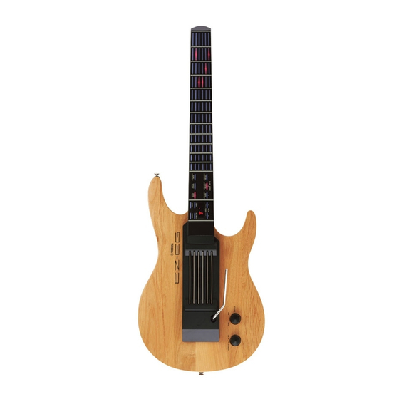
Dimensions (w x d x h) 809 x 300 x 72 mm (32" x 11-3/4" x 3") Weight 1.6 kg (3 lbs. 8oz.) (w/o batteries) Supplied Accessories Tremolo Arm, Strap, C-Clip x 2, Pick, AC Power Adaptor, EZ-EG Song Chord Chart, USB-MIDI Interface (UX16), CD-ROM... -
Page 4: Panel Layout
EZ-EG PANEL LAYOUT Body Frets Tremolo Arm Control Section [VOLUME] Control knob Strings [STANDBY/ON] Control switch Control Section Connectors 18 19 VALUE [+]/[-] buttons MIDI IN/MIDI OUT connectors Display PHONES/OUTPUT jack [BALANCE] button DC IN 9V jack [TUNING] button [TEMPO] button... -
Page 5: Circuit Board Layout
EZ-EG CIRCUIT BOARD LAYOUT Body assembly CN801 AM-1 Lower case assembly CN501 CN604 CN601 CN701 CN602 Neck assembly AM-2 AM-3 Strings sensor unit CN902 CN901 MUTE 1/2 Vibrato arm unit... - Page 6 SENSOR SPEAKER STRING TREMOLO LD90 9,10 UNIT S1–S6 SW MATRIX UNIT PIEZO S[0–11] K1–K6 S[0–11] D[0–7] D[0–7] SENSOR 15 36 8,9 MUTE 1/2 L[0–15] L[0–15] LED MATRIX 7 Seg LED Driver CLOCK D[1–7] TREMOLO L[12–14] TA1–3 8.00 MHz VR901 AM-3 AM-2 AM-2 1–7...
-
Page 7: Disassembly Procedure
EZ-EG DISASSEMBLY PROCEDURE Lower Case Assembly DM Circuit Board (Time required: about 5 minutes) (Time required: about 10 minutes) Pull out the POWER knob and the VOLUME knob. (Fig. 1) Remove the lower case assembly. (See procedure 1.) Remove the seven (7) screws marked [150]. The lower case Remove the four (4) screws marked [220]. - Page 8 EZ-EG AM-3 Circuit Board Strings Sensor Unit, Upper Case (Time required: about 15 minutes) (Time required: about 15 minutes) Remove the lower case assembly. (See procedure 1.) Remove the lower case assembly. (See procedure 1.) Remove the DM circuit board. (See procedure 3.) Remove the DM circuit board.
-
Page 9: Lsi Pin Description
EZ-EG PN Circuit Board, Key Top Rubber (Time required: about 8 minutes) Remove the lower case assembly. (See procedure 1.) The neck is attached to the body. It cannot be removed. Remove the three (3) screws marked [N100]. The earth plate Remove the two (2) screws marked [N70] from the finger- can then be removed. - Page 10 EZ-EG HG73C205AFD (XU947C00) SWX00B (Tone Generator) DM: IC101 NAME FUNCTION NAME FUNCTION Initial clear CMA3 Program address bus RFCLKI PLL Clock CMA8 Program address bus PLL Control CMA2 Program address bus AVDD_PLL Power supply read signal AVSS_PLL Ground CMA1 Program address bus...
-
Page 11: Block Diagram
EZ-EG IC BLOCK DIAGRAM 74HCU04DT (XZ110A00) HD74LVC08FP (XU720A00) MM74HC14SJX (XW104A00) Hex Inverter Quad 2 Input AND Hex Inverter DM: IC607 DM: IC306 DM: IC702 TC74HC4053AFT (XV944A00) µPC4572G2-T1 (XF634A00) µPD6379AGR (XR998A00) Multiplexer/Demultiplexer NJM2904V(TE1) (XR532A00) D/A Converter Dual Operational Amplifier DM: IC701... -
Page 12: Circuit Boards
EZ-EG CIRCUIT BOARDS AM-1 (X2281C0) ··········································· 13 PN (X2282C0) ··············································· 14/15 AM-2 (X2281C0) ··········································· 13 MUTE 1/2 (X2284B0) ··································· 13 AM-3 (X2281C0) ··········································· 13 MUTE 2/2 (X2284B0) ··································· 13 DM (X3209A0) ·············································· 12 Note: See parts list for details of circuit board component parts. - Page 13 EZ-EG AM-1 Circuit Board AM-3 Circuit Board TREMOLO to DM-CN501 to DM-CN602 Component side VOLUME : VR801 and SW801 are mounted POWER ON/ in pattern side. STANDBY : Do manual solder to JK801 after dip-soldering. BATTERY MIDI IN MIDI OUT...
- Page 14 EZ-EG PN Circuit Board to DM-CN701 STRING-1 STRING-2 STRING-3 STRING-4 STRING-5 STRING-6 Component side 2NA-V861540-1...
- Page 15 EZ-EG PN Circuit Board FRET-1 FRET-2 FRET-3 FRET-4 FRET-5 FRET-6 FRET-7 FRET-8 FRET-9 FRET-10 FRET-11 FRET-12 PLAY MODE STRUM CHORD BOTH DEMO SOUND SONG VALUE+ VALUE- TEMPO BALANCE CAPO TUNING Pattern side 2NA-V861540-2...
-
Page 16: Test Program
EZ-EG TEST PROGRAM Preparation PA-D09 (AC adaptor) is used. Set the [MASTER VOLUME] to maximum. Jigs: Frequency counter, level meter (with JIS-A filter), MIDI cable Note) Connect a stereo plug to the [PHONES/OUTPUT] jack at 33 ohms. Please refer to the Internet site below for information and the procedure for transferring data. - Page 17 EZ-EG TEST 7-seg. LED for Each Test Test Function and Judgment criteria Check the switches and the LEDs on the panel. Turn on the switches as shown on the LEDs in the sequence indicated in TABLE 1 (P.18). A sound is generated while the fret switch is on. (Without key stick) Press the [DEMO] switch to interrupt operation.
-
Page 18: Inspections
EZ-EG <TABLE1> DEMO SOUND SONG STRUM CHORD BOTH TEMPO BALANCE CAPO 1st fret of 2nd fret of 12th fret of 1st fret of 12th fret of TUNING – 1st string 1st string 1st string 2nd string 6th string 6 11 12... -
Page 19: Midi Implementation Chart
EZ-EG MIDI IMPLEMENTATION CHART YAMAHA [ Easy Guitar ] Date: 26-Nov-2002 Model EZ-EG MIDI Implementation Chart Version: 1.0 Function... Transmitted Recognized Remarks Basic Default 1 - 6 1 - 16 Channel Changed 1 - 16 Default Mode Messages Altered **************... - Page 20 EZ-EG EZ-EG functions as a 16-channel multi-timbral tone generator, and incoming data does not affect the panel voices or panel settings. However, the MIDI messages listed below do affect the panel voices and songs. • MIDI Master Tuning Exclusive <GM System ON>...
-
Page 21: Parts List
PARTS LIST CONTENTS OVERALL ASSEMBLY ···························································································································· 2 STRINGS SENSOR UNIT ······················································································································· 4 ELECTRICAL PARTS ························································································································ 6~11 Notes: DESTINATION ABBREVIATIONS Australian model M: South African model British model O: Chinese model Canadian model Q: South-east Asia model German model Taiwan model European model U.S.A. - Page 22 EZ-EG OVERALL ASSEMBLY Vibrato Arm Neck Assembly Strings Sensor Unit (See page 4.) N110 N130 N130a N100 Vibrato Arm Unit The neck is attached to the body It cannot be removed. Body Assembly Lower Case Assembly L120 L120 L140 L120...
-
Page 23: Parts List
EZ-EG PART NO. DESCRIPTION REMARKS REF NO. QTY RANK OVERALL ASSEMBLY EZ-EG Overall Assembly (V851660) Overall Assembly (WA53130) V9561200 Body Assembly Body (V851670) BB801510 End Pin Chrome VB793700 Felt EN230140 Oval Head Tapping Screw 3.0X25 CHROME V8519900 Upper Case V8529300 Bind Head Tapping Screw-P 3.0X30 MFZN2BL... - Page 24 EZ-EG PART NO. DESCRIPTION REMARKS REF NO. QTY RANK L130 V8521800 Battery Cover L140 Connector Assembly C&C 11P 160L (V938330) : New Parts RANK: Japan only STRINGS SENSOR UNIT 230b (With no pattern) 230a (With a pattern) is attached to...
- Page 25 EZ-EG PART NO. DESCRIPTION REMARKS REF NO. QTY RANK V8523100 STRINGS SENSOR UNIT EZ-EG Sensor Base (V852350) X2279A00 Speaker Speaker Wire SP L=60 WHITE/RED (V886700) V8615800 Spacer Sensor Holder A (V852320) Sensor Holder B (V852330) Sensor 7BB12-9A6 Piezo (V905470) EP630220 Bind Head Tapping Screw-P 3.0X8 MFZN2BL...
-
Page 26: Electrical Parts
EZ-EG ELECTRICAL PARTS PART NO. DESCRIPTION REMARKS REF NO. QTY RANK ELECTRICAL PARTS EZ-EG AAX34840 Circuit Board AM-1 (V611530)(X2281C0) AAX34850 Circuit Board AM-2 (V861530)(X2281C0) AAX34860 Circuit Board AM-3 (V861530)(X2281C0) AAX34830 Circuit Board (V847030)(X2280C0) AAX43860 Circuit Board (WA08980)(X3209A0) AAX34870 Circuit Board... - Page 27 EZ-EG PART NO. DESCRIPTION REMARKS REF NO. QTY RANK Connector Assembly 2426&1018 3P 100L (V644610) AAX34830 Circuit Board (V847030)(X2280C0) AAX43860 Circuit Board (WA08980)(X3209A0) C0101 UX061270 Ceramic Capacitor (chip) 27P 50V J C0102 UX061270 Ceramic Capacitor (chip) 27P 50V J C0103...
- Page 28 EZ-EG PART NO. DESCRIPTION REMARKS REF NO. QTY RANK C0711 UX062100 Ceramic Capacitor (chip) 100P 50V J CN501 VV068500 Connector Base Post M2426XXR 11P SE CN601 VV068300 Connector Base Post M2426XXR 9P SE CN602 VV067700 Connector Base Post M2426XXR 3P SE...
- Page 29 EZ-EG PART NO. DESCRIPTION REMARKS REF NO. QTY RANK R0050 RG006560 Carbon Resistor (chip) 5.6K 0.1 J R0051 RG008100 Carbon Resistor (chip) 100K 0.1 J R0052 RG007100 Carbon Resistor (chip) 10K 0.1 J -0057 RG007100 Carbon Resistor (chip) 10K 0.1 J...
- Page 30 EZ-EG PART NO. DESCRIPTION REMARKS REF NO. QTY RANK R0604 RG007100 Carbon Resistor (chip) 10K 0.1 J R0611 RG008100 Carbon Resistor (chip) 100K 0.1 J R0701 RG006470 Carbon Resistor (chip) 4.7K 0.1 J -0704 RG006470 Carbon Resistor (chip) 4.7K 0.1 J...
- Page 31 EZ-EG PART NO. DESCRIPTION REMARKS REF NO. QTY RANK LD046 V8573500 KPH-1608SRC-PRV 8F-4Str LD047 V8573500 KPH-1608SRC-PRV 8F-5Str LD048 V8573500 KPH-1608SRC-PRV 8F-6Str LD049 V8573500 KPH-1608SRC-PRV 9F-1Str LD050 V8573500 KPH-1608SRC-PRV 9F-2Str LD051 V8573500 KPH-1608SRC-PRV 9F-3Str LD052 V8573500 KPH-1608SRC-PRV 9F-4Str LD053 V8573500 KPH-1608SRC-PRV...
-
Page 32: Parts List
EZ-EG OVERALL CIRCUIT DIAGRAM 1/2 ( DM ) EZ-EG : Ceramic Capacitor Note: See parts list for details of circuit board component parts. DC-DC CONVERTER PQ1CZ1T (XR404A00) µPC2933T-E1 (XS516A00) OP AMP DC-DC CONVERTER REGULATOR +3.3V INVERTER OP AMP 1: VIN... -
Page 33: Parts List
EZ-EG OVERALL CIRCUIT DIAGRAM 2/2 ( AM-1, AM-2, AM-3, MUTE 1/2, PN ) EZ-EG 本资料由OKXIA视听皮带资源库www.okxia.cn提供 to DM-CN601 AM-1 AM-3 BATTERY MUTE 1/2 (SUM 3 x 6) to DM-CN602 DC-IN 9V to DM-CN604 to DM-CN501 28CA1-8822925 28CC1-8824158 PHONE/OUTPUT PIEZO SENSOR POWER AMP...
Need help?
Do you have a question about the EZ-EG and is the answer not in the manual?
Questions and answers