Table of Contents
Advertisement
Advertisement
Table of Contents
Troubleshooting

Subscribe to Our Youtube Channel
Summary of Contents for DoraniX ThermaPrint 64
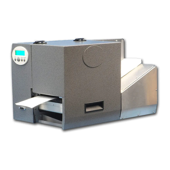
- Page 1 ThermaPrint 64 User’s Manual from DoraniX...
-
Page 2: Table Of Contents
Thermaprint 64 User Manual Table of Contents Quick Start Menu ........................ 4 Printer ..........................5 Printer Interface ......................5 Power Stacker ......................... 6 Single-Start Catch Tray....................7 Ramp Positioning ......................7 Separator ......................... 8 Software Settings ......................8 X-adjust print location ....................9 Introduction ........................ - Page 3 Thermaprint 64 User Manual INTERF. PARAM......................28 SYSTEM PARAMETERS ................... 28 Foil end warning ....................... 28 Foil warn stop ......................28 Autom. dot check ...................... 28 Early dottest ......................29 Latest dottest ......................29 Dottestarea from......................29 Dottestarea to ......................30 Print Interpret.
-
Page 4: Quick Start Menu
Thermaprint 64 User Manual Quick Start Menu... -
Page 5: Printer
Thermaprint 64 User Manual Printer 1. Remove printer from box and place all shipping materials in a location where they can be used later should the printer need to be shipped back for repair. 2. Follow the setup instructions in the following pages for any options your printer may have. -
Page 6: Power Stacker
Thermaprint 64 User Manual Power Stacker Parts 6 red screws (4 large, 2 small) 1 sheet metal shield 1 stacker housing 2 stacker rods 2 4mm screws 1 stacker tray Magnetic guide(s) (standard: could change if custom design needed) Assembly 1. -
Page 7: Single-Start Catch Tray
Thermaprint 64 User Manual Single-Start Catch Tray Parts 2 red-capped screws 1 single-start catch tray Assembly Attach the tray to the front of the printer using the 2 red screws. Options Turn Single-Start Function On/OFF Go into the menu and go to System Parameters > Periph. Device > Single Start (to enable function) or none (to disable function) and then press Online to select. -
Page 8: Separator
Thermaprint 64 User Manual If the ramp does not seem to help the feeding process as it should after placed as shown, move it slightly either forward or back as necessary until it reaches the desired feeding performance. If supplied with a 1” wide ramp, it will likely need to be placed between the agitator wheel and the wall of the printer. -
Page 9: X-Adjust Print Location
6ips. If you feel as if this speed is not what it should be, please contact DoraniX technical support at 303-271-0986. Label Length: It is very important that the length of the product is set correctly in the software. -
Page 10: Introduction
Below, in Figure 1, is a picture of the Thermaprint 64 with the cover opened, and provides a detailed call out of the various components and modules. The terms provided in Figure 1 will be used throughout the rest of this manual for consistency. - Page 11 Thermaprint 64 User Manual ribbon onto the ribbon supply mandrel so that the ribbon will unwind with the coated side facing down. Place an empty ribbon core on the ribbon take-up mandrel. For coated side in ribbons, the ribbon roll will unwind in a counter-clockwise direction and the ribbon will come off the top side of the roll.
-
Page 12: Operation
Below is a graphical explanation of how to access, navigate, and exit the menu system within the Thermaprint 64. A full list of all the available sub menus (Print Info, Print Parameters, etc.) and functions (Printer Status, Print Speed, etc.) within each sub menu is available in Appendix A. -
Page 13: Troubleshooting
Cut + Online + Feed Restarts the printer Troubleshooting There are 2 types of error messages given by the Thermaprint 64, self-acknowledging messages and error reports. Messages beep once and display a short message detailing the message. They acknowledge themselves after a moment, and go away on their own. Generally these... -
Page 14: Troubleshooting
Thermaprint 64 User Manual turn the beeper off, but leave the error displayed, and pressing the enter button will acknowledge the error and return the machine to the state it was in when the error was interrupted. It may be necessary to press the feed button to resume printing if that is when the error occurred. - Page 15 Thermaprint 64 User Manual Ensure that the sensor is set to the correct mode. To do this, enter the menu system, enter the SYSTEM PARAMETERS submenu, and under the option Light sens. type ensure that the correct sensor type is selected. Check the provided recommended settings to determine the correct sensor type.
-
Page 16: Maintenance
Thermaprint 64 User Manual Maintenance Interval and Cleaning products Regular servicing and cleaning work is necessary for safe operation and high running performance. The servicing intervals are dependent on the operation and ambient conditions, daily operating times, and the print medium. Regularly clean the print head and feed roller by removing any paper, adhesive, and ribbon residues using a dust-free cloth and a neutral cleaning solution. -
Page 17: Changing The Print Head
Thermaprint 64 User Manual 6. After cleaning, return the print head module to its original position and re-tighten the thumb screws. 7. Press the thumb screw on the tapered edge of the square shaft and ensure the exact positioning of the print head module on the contact shaft. Also pay attention to the position of the print head in relation to the edge of the label. -
Page 18: Cleaning The Belts And Rollers
Thermaprint 64 User Manual Fig. 8: Take care not to touch the connector contacts (1) or the thermal edge (2) when removing the print head. CAUTION! - The print head is a sensitive electronic component and can be damaged by electrostatic charges. Therefore, discharge any bodily static electricity before coming into contact with the print head by touching the base plate of the printer. - Page 19 Thermaprint 64 User Manual 4. Unscrew the two thumb screws on the print head module until the entire print head module can be rotated clockwise on the contact shaft. The print head does not need to be removed. Mark the position of the print head on the contact shaft if it is not against the inside wall or outside stop.
-
Page 20: Appendix A: Menu System And System Preferences
Appendix A: Menu System and System Preferences In this appendix, submenus will have their names bolded and fully capitalized. The functions within each submenu will be underlined, with the description and any selections indented to allow for quick visual access. Changing the values and settings for many of these parameters can severely and negatively affect print quality and speed, while also possibly affecting product detection and transportation. -
Page 21: Font Status
Figure 2A: Sample Memory Status printout Font status Print samples of all installed characters, bar codes and line samples (several pages). The section of the printout titled Font Library shows a list of the internal fonts and line styles and the section titled Barcode Library shows a list of the internal 1D and 2D barcode formats. -
Page 22: Service Status
Figure 4A: Sample Barcode Library printout. Service Status Print the Service status report to read about operation time, no. of services, no. of exchanged parts and other matters of service interest (one page). -
Page 23: Dottest Endless
Figure 5A: Sample Service Data printout Dottest endless Not for use with Thermaprint 64. See Dottest punched. Dottest punched Dot test for application with punched label stock. This function prints a pattern which enables trained personnel to check the adjustment as well as the function of the print head. -
Page 24: Print Parameters
Figure 6A: Sample Reference Label PRINT PARAMETERS Print speed The print speed (material feed) can be adjusted according to the ribbon and material combination being used in order to optimize the contrast depth and the density of the print image. inch/s Setting range: see table;... -
Page 25: Material Type
(hole gaps, self-adhesive material with register gaps). The detected gap position corresponds to the start of the label. Endless: If material is to be used without gaps. Not recommended for the Thermaprint 64. Punched: If material is to be used with gaps (default setting) Material length The material length (label length) is the distance between the gaps, measured from the front edge (beginning) of a label to the front edge of the next label. -
Page 26: Punch Offset
Punch offset The zero position can be determined offset in millimeter units from the detected gap position, as shown in Figure 7A. Figure 7A: Visual representation of Punch offset setting. xxx mm: Setting range: -5 to +max. label length; Unit interval: 0.1mm Default setting: 0 mm Maximum offset in feed direction: -5 mm Minimum offset against feed direction: +max. -
Page 27: Ean Sep. Lines
EAN sep. lines Parameter for controlling of EAN or UPC barcodes if they are printed without read line. With readl. only (Default) The separation bars at the beginning, end and in the middle of the barcode are only long, if the barcode is printed with a read line. Always long The separation bars at the beginning, end and in the middle of the barcode are always long, regardless if the barcode is printed with or without read line. -
Page 28: Punch Mode
• Maximum offset in feed direction: +5.0 mm • No offset: 0.0mm • Minimum offset against feed direction: -5.0 mm Punch mode Determine whether the sensor threshold level is set manually or automatically. Automatic Use this setting for materials with a contrast zone or gap in the label. Automatic is the default setting, suitable for all materials with which there is a difference in the transparency between the product and gap of more than 2 values Manual Use this setting for materials with several varying contrast zones. -
Page 29: Interf. Param
A setting value of 50 means that all readings over 50 are considered product, therefore the printer will consider the labels as the product, and the black bars will not affect printing. A setting between the values of 30 and 60 is ideal for this application. INTERF. -
Page 30: Early Dottest
from, Dottestarea to determine the conditions under which the dot check is executed. The four specified parameters appear in the menu only if continuous has been selected. Power on only The dot check is preceded immediately after powering on the printer. -
Page 31: Dottestarea To
Dottestarea to Only displayed if SYSTEM PARAMETER > Autom. dot check = Continuous. Upper border of the dot check area. The value sets the distance in mm to the left print head end, looked at on the print head from above. x mm Setting range: refer to Tab. -
Page 32: Ribbon Autoecon
Ribbon autoecon. The ribbon feed can be interrupted during print periods with the ribbon automatic economy parameter. This saves ribbon, particularly with long labels with a minimum print area. The automatic function should only be activated with unprinted areas from approx. -
Page 33: Single Job Mode
Single job mode In single job mode (also stop mode) the printer stops after every job and waits until the operator restarts the print process. Deactivated Single job mode is switched off (default setting). Activated Single job mode is switched on. The printer always displays "Start next job", before starting a new print job. -
Page 34: Voltage Offset
• xx%: Up to xx% temperature reduction with a hot print head. Voltage offset The voltage offset increases the head voltage and therefore the head temperature which e.g. was set by Easy Plug command (HV). xx% Setting range: 0 to 20%; Unit interval: 1% Default setting: 0% Miss. -
Page 35: Periph. Device
Reflex Material end detection by means of a reflex sensor. Transparent Material end detection by means of a transmission sensor. Disabled No material end detection. Periph. device After installation, options must be selected under "Peripheral device" in order to be assured of the corresponding sensor queries and printer reactions. -
Page 36: Start Source
Edge The rising / falling signal edge triggers the printing of exactly one label (Default setting). See parameter Signal edge on page 23. Start source Choose a signal source for the start signal: Foot switch Optional foot switch is used to generate the start signal. Light barrier (Default setting) Photoelectric switch at the dispensing edge which detects the taking off of the printed product. -
Page 37: Service Function
interrupted print job, is deleted! Service Function Do not adjust any of the settings in this sub-menu without contacting a service technician. Heat Settings When printing, the heat should be set dependent on the ribbon being used. The optimal heats for various ribbons can be seen in the table below. Ribbon Heat (%) -
Page 38: Appendix B: External Attachments
Appendix B: External Attachments Power Stacker Parts 6 red screws (4 large, 2 small) 1 sheet metal shield 1 stacker housing 2 stacker rods 2 4mm screws 1 stacker tray Magnetic guide(s) (standard: could change if custom design needed) Assembly 1. - Page 39 Options Turn Single-Start Function On/OFF Go into the menu and go to System Parameters > Periph. Device > Single Start (to enable function) or none (to disable function) and then press Online to select. Change the number of products printed at a single time ...
-
Page 40: Appendix C: Parts Callout
Appendix C: Parts Callout Part Name Part Number 1 Printhead Pressure Selector 98220 2 Ribbon Take-Up Mandrel (64-04/05, 64-06, 64-08) 98319, 98672, 99938 3 Ribbon Supply Mandrel (64-04/05, 64-06, 64-08) 98318, 98673, 99937 4 Seperator Gap Adjustment Knob 99000 5 Ribbon Drive Platen (64-04/05, 64-06, 64-08) 98171, 98584, 99608 6 Ribbon Guide (64-04/05, 64-06, 64-08) 98137, 98589, A0214... -
Page 42: Appendix D: Replacement Parts List
Appendix D: Replacement Parts List Part Name Part Number Printhead Pressure Selector 98220 Ribbon Take-Up Mandrel (64-04/05, 64-06, 64-08) 98319, 98672, 99938 Ribbon Supply Mandrel (64-04/05, 64-06, 64-08) 98318, 98673, 99937 Seperator Gap Adjustment Knob 99000 Product Guide Adjustment Knob 99001 Printhead Hold-Down Screws A1004... - Page 43 37 Blue Transport Belt (Rough) 99009 38 Extension Feed Tray 99015 39 Static Brush 99016 40 Static Brush Ground Cable 99017 41 Red Capped Thumb Screws (4mm) 99018 42 Red Capped Thumb Screws (1/4”) 99019 43 Feed Shaft (6” Printer) 99020 44 Feed Shaft (10”...
-
Page 44: Appendix E: Universal Interface Board (Optional)
Appendix E: Universal Interface Board (Optional)
Need help?
Do you have a question about the ThermaPrint 64 and is the answer not in the manual?
Questions and answers
I need to purchase replacement print heads for my Doranix Thermal Printer 64. What type of head is it and what is the part number?