Advertisement
Table of Contents
- 1 Table of Contents
- 2 Pre-Installation Instructions
- 3 Bypass Valve
- 4 General Installation
- 5 Installation Instructions
- 6 Manual Regeneration
- 7 Troubleshooting Guide
- 8 Specifications
- 9 Component Parts Breakdown & List
- 10 Control Valve Breakdown
- 11 Control Valve Parts List
- 12 Installation Fitting Assemblies
- 13 Quick Reference Guide
- Download this manual
Advertisement
Table of Contents

Related Manuals for Sterling IFS10

Summary of Contents for Sterling IFS10
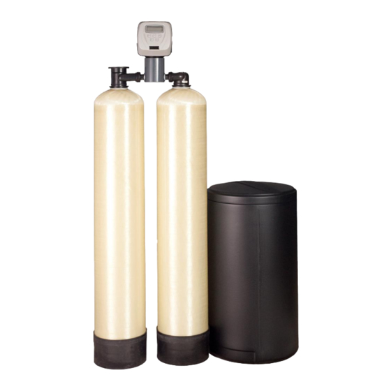
- Page 1 Installation Instructions and Owner’s Manual IFS Series Iron Filter / Softener System Sterling Water Treatment 12630 US Highway 33 N Churubusco, IN 46723 Phone (260) 693-1972 Fax (260) 693-0602 www.sterlingwatertreatment.com IFS Instruction Manual 140326.docx...
-
Page 2: Table Of Contents
TABLE OF CONTENTS Pre-installation Instructions Page 2 Bypass Valve Page 5 General Installation Page 6 Installation Instructions Page 7 Control Valve Programming – Set Time-of-Day Page 9 Control Valve Programming – Initial Settings Page 9 Control Valve Operating Displays Page 11 Troubleshooting Guide Page 12 Specifications... -
Page 3: Pre-Installation Instructions
7.0, lower values indicate acidic water. The IFS performs best when the pH is 7.0, or higher. The IFS10 uses Iron Pro media blend in the filter in order to elevate low pH for proper iron oxidation. - Page 4 Water Supply Unlike other iron filters that do not use chemicals to oxidize the iron, the IFS iron filter portion does not require additional plumbing such as solenoid valves, pressure switches or pressure tanks. This filter will function properly when the water supply is furnished by a jet pump, submersible pump, variable speed (constant pressure) pump or community water supply.
- Page 5 The manufacturer has set the water treatment unit’s sequence of cycles, cycle times, salt dose, exchange capacity and gallon capacity. The salt dose refill time has been preset. The dealer should read this page and guide the installer regarding hardness, day override, and time of regeneration, before installation: For the installer, the following sections should be read: ...
-
Page 6: Bypass Valve
Bypass Valve The bypass valve is used to isolate the control valve from the plumbing system's water pressure in order to perform control valve repairs or maintenance. The 1" full flow bypass valve incorporates four positions including a diagnostic position that allows a service technician to have pressure to test a system while providing untreated bypass water to the building. -
Page 7: General Installation
General Installation GENERAL INSTALLATION & SERVICE WARNINGS The control valve, fittings and/or bypass are designed to accommodate minor plumbing misalignments. There is a small amount of “give” to properly connect the piping but the water softener is not designed to support the weight of plumbing. -
Page 8: Installation Instructions
HAND TIGHTEN UNION NUTS ONLY. DO NOT OVERTIGHTEN. Outlet to service Inlet from water supply Brine Refill Elbow and BLFC Retainer Clip Brine Line Flow Control Assembly Drain Line Flow Control Assembly DLFC Retainer Clip (DLFC Elbow Fitting not shown) FIGURE 3: Top View of IFS10... - Page 9 STEP 6: Shut off water at main supply. Relieve pressure by opening nearest faucet. On private well systems, turn off power to pump and drain pressure tank. SHUT OFF POWER OR FUEL SUPPLY TO WATER HEATER. STEP 7: Cut main supply line as required to fit plumbing to inlet and outlet of bypass valve. DO NOT PLUMB INLET AND OUTLET BACKWARDS.
- Page 10 Programming Procedures for the IFS 1. Set Time of Day: Time of day should only need to be set after extended power outages or when daylight saving time begins or ends. If an extended power outage occurs, the time of day will flash on and off indicating that the time should be reset.
- Page 11 2. Programming cont’d: STEP 4 -- Regeneration Hour: The manufacturer has factory set 2:00 am as the default. This is the buttons. “AM/PM” toggles hour of day for regeneration and can be reset by using after 12. The default time is 2:00 a.m. (recommended for a normal household). Press next to go to step 5.
-
Page 12: Manual Regeneration
Operating Displays for the IFS 1. General Operation: When the system is operating, one of the three displays may be shown. Pressing next will alternate between displays. One of the displays is always the current time of day. The second display shows the current treated water flow rate through the system in Gallons Per Minute (gpm). - Page 13 TROUBLESHOOTING PROBLEM CAUSES SOLUTIONS A) Loose nut at either end of the brine line B) Brine line inserted into the brine tank 1) Tighten nuts at either end of brine line overflow fitting 2) Verify brine line is installed correctly rather than 3) Verify softener drain line is not connected connected to the...
-
Page 14: Troubleshooting Guide
1) See “Brine tank overfills” section (Page 12) “E” in Brine Tank 2) Resolve drain line issues Overfill section) 3) Contact Sterling technical support for C) Rinse cycle is short Salty Water assistance in verifying \ adjusting Rinse D) Salt setting too high... - Page 15 TROUBLESHOOTING (continued) PROBLEM CAUSES SOLUTIONS A) Outlet is on a switch Display shows B) Power outage 1) Use an un-switched outlet incorrect time-of-day C) Control valve was 2) Reset time-of-day or time-of-day flashes reset 3) Replace circuit board if needed D) Defective circuit board ERROR CODE:...
-
Page 16: Specifications
SPECIFICATIONS: UNIT MODEL NUMBER IFS10 MEDIA VOLUME (ft CAPACITY (grains) @Minimum Salt Setting (6#/ft 18,000 @Factory Salt Setting (9#/ft 21,000 @Maximum Salt Setting (15#/ft 32,000 SERVICE FLOW RATES (gpm) Continuous Peak PRESSURE LOSS (psi) @ Continuous Flow Rate @ Peak Flow Rate... - Page 17 THIS PAGE INTENTIONALLY LEFT BLANK...
-
Page 18: Component Parts Breakdown & List
Component Parts Breakdown... - Page 19 Nut, 1” Quick Connect CV3151 OX-7 Back Tube Adaptor CV3150 Split Ring Retainer Complete Control Valve includes backtube assy IFS10 VLV ASSY W/BP (ref #12) and bypass valve CD1400 Distributor Head CD1220-01 Distributor Head w/Fillport Distributor Tube, 1” x 54”...
-
Page 20: Control Valve Breakdown
Control Valve Breakdown... -
Page 21: Control Valve Parts List
Control Valve Parts List REF # Part Number Description CV3002CC Drive Assembly, IM Series CV3186 Power Cord with Transformer CV3003 Meter and Cable Assembly CV3006 Bypass Valve, Less Fittings CV3175CC-01GR Front Cover, Gray CV3107-01 Drive Motor CV3108CC Circuit Board CV3004 Drive Cap Assembly CV3135 O-ring, -228... -
Page 22: Installation Fitting Assemblies
Installation Fitting Assemblies 3/4" & 1" PVC SOLVENT ELBOW 1" PVC MALE NPT ELBOW Part # Description Part # Description 3/4" & 1" PVC solvent CV3007-01 1" PVC male NPT CV3007 elbow assy elbow assy CV3151 Nut, 1" quick connect CV3151 Nut, 1"... - Page 23 Installation Fitting Assemblies Continued 1" BRASS SHARK BITE 3/4" BRASS SHARK BITE Part # Description Part # Description 1" brass shark bite CV3007-13 3/4" brass shark bite CV3007-12 assembly assembly CV3151 Nut, 1" quick connect CV3151 Nut, 1" quick connect CV3150 Split ring CV3150...
- Page 24 Installation Fitting Assemblies Continued 3/4" QUICK CONNECT Description Part # 3/4" QUICK CONNECT QFNCR4 (*2 required) SERVICE WRENCH - CV3193 Although no tools are necessary to assemble or disassemble the valve, the Service Wrench, (shown in various positions on the valve) is available to aid in assembly or disassembly.
-
Page 25: Quick Reference Guide
Quick Reference Guide...
Need help?
Do you have a question about the IFS10 and is the answer not in the manual?
Questions and answers