Table of Contents
Advertisement
Solar water heating systems
Installation • Operation • Maintenance
CLI U12 SD0(W/L/F/P)118 El B/U
CLI U12 SK0(W/L/F/P)218 El B/U
CLI U12 SK0(W/L/F/P)318 El B/U
Solar with electric element back-up
CLI U12 SD0(W/L/F/P)119 HX B/U
CLI U12 SK0(W/L/F/P)219 HX B/U
CLI U12 SK0(W/L/F/P)319 HX B/U
Solar with heat exchanger back-up
CLI U12 SD0(W/L/F/P)11(10/12) NG B/U
CLI U12 SK0(W/L/F/P)21(10/12) NG B/U
Solar with natural gas back-up
CLI U12 SD0(W/L/F/P)11(11/13) LP B/U
CLI U12 SK0(W/L/F/P)21(11/13) LP B/U
Solar with propane back-up
The solar energy system described in this manual, when properly installed and maintained,
This certification does not imply endorsement or warranty of this product by SRCC.
meets the minimum standards established by the SRCC.
CLI U12 SD0(W/L/F/P)118 AUX EL
CLI U12 SK0(W/L/F/P)218 AUX EL
CLI U12 SK0(W/L/F/P)318 AUX EL
Solar pre-heat to electric tank water heater
CLI U12 SD0(W/L/F/P)118 AUX GAS
CLI U12 SK0(W/L/F/P)218 AUX GAS
CLI U12 SK0(W/L/F/P)318 AUX GAS
Solar pre-heat to gas tank water heater
CLI U12 SD0(W/L/F/P)118 AUX TLG
CLI U12 SK0(W/L/F/P)218 AUX TLG
CLI U12 SK0(W/L/F/P)318 AUX TLG
Solar pre-heat to tankless gas water heater
Advertisement
Table of Contents

Related Manuals for Velux CLI U12 SD0W118 El B/U

Summary of Contents for Velux CLI U12 SD0W118 El B/U
- Page 1 Solar water heating systems Installation • Operation • Maintenance CLI U12 SD0(W/L/F/P)118 El B/U CLI U12 SD0(W/L/F/P)118 AUX EL CLI U12 SK0(W/L/F/P)218 El B/U CLI U12 SK0(W/L/F/P)218 AUX EL CLI U12 SK0(W/L/F/P)318 El B/U CLI U12 SK0(W/L/F/P)318 AUX EL Solar with electric element back-up Solar pre-heat to electric tank water heater CLI U12 SD0(W/L/F/P)119 HX B/U CLI U12 SD0(W/L/F/P)118 AUX GAS...
-
Page 2: Table Of Contents
Page – 36 − Installation check list Page – 6 Part 5: Specifications Page – 37 − VELUX solar system with electric or gas back-up Page – 7 − VELUX solar collector Page – 37 − VELUX solar system with boiler back-up Page –... -
Page 3: Part 1: Product And Safety Information
Local installation regulation Installation of the VELUX solar water heating system may be governed by local rules and regulations for this type of product. The installation must be done in accordance with those regulations. Always use the latest edition of codes. The installation, adjustment, service and maintenance of the VELUX solar water heating system must be done by a licensed professional who is qualified and experienced in the installation, service and maintenance of solar hot water systems. -
Page 4: Part 2: General Information
The VELUX solar water heating system is designed to produce domestic hot water from either solar collectors, an electrical backup, a gas backup, or a boiler back up (provided by others). The VELUX systems can also be used as a solar preheat system to conventional electric, gas, or tankless water heaters (provided by others). -
Page 5: Solar Storage Tank
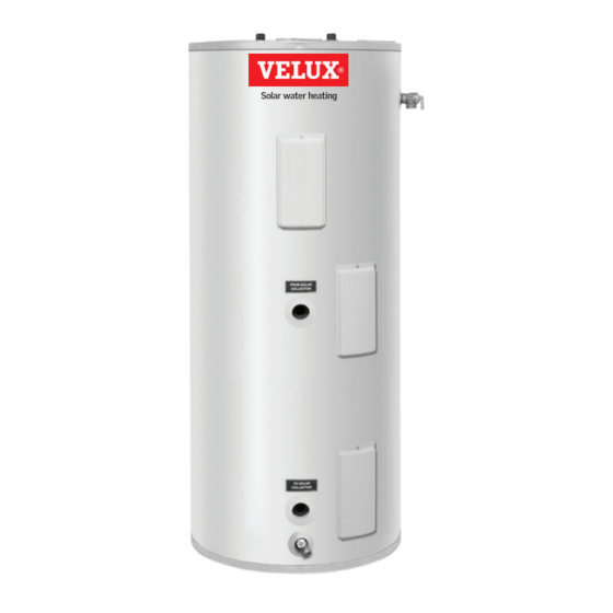
Solar storage tank All VELUX solar water heating systems will include a solar storage tank with the solar heat exchanger located in the bottom section of the tank to heat the entire water volume of the tank. The thermostatic controls for the electric, gas, or boiler back up shall be located in the upper portion of the tank to provide back up heat if the solar collector is not providing enough heat to maintain the upper operating set point of the tank. -
Page 6: Installation Check List
Part 3: Solar water heater system installation The Contractor shall obtain all required permits and approvals for installing the solar system. The installation shall conform to all federal, state and local regulations governing solar water heating system installations. The contractor shall adhere to sound building safety and trade practices. - Page 7 VELUX solar water heating system with electric or gas back-up System models: CLI U12 SD0(W/L/F/P) 118 El B/U CLI U12 SD0(W/L/F/P) 1110 NG B/U CLI U12 SD0(W/L/F/P) 1111 LP B/U CLI U12 SK0(W/L/F/P) 218 El B/U CLI U12 SK0(W/L/F/P) 2110 NG B/U CLI U12 SK0(W/L/F/P) 2111 LP B/U...
- Page 8 VELUX solar water heating system with boiler back-up System models: CLI U12 SD0(W/L/F/P) 119 HX B/U CLI U12 SK0(W/L/F/P) 219 HX B/U CLI U12 SK0(W/L/F/P) 319 HX B/U 1. Collectors 2. Flashing/racking 3. Connector tube 4. Flextubes 5. Air Separator 6.
- Page 9 VELUX water heating system with tankless back-up System models: CLI U12 SD0(W/L/F/P)118 AUX TLG CLI U12 SK0(W/L/F/P)218 AUX TLG CLI U12 SKO(W/L/F/P)318 AUX TLG 1. Collectors 2. Flashing/racking Cold water 3. Connector tube Hot water 4. Flextubes 5. Air Separator 6.
-
Page 10: Velux Solar Pre-Heat Water Heating System
VELUX solar pre-heat water heating system System models: CLI U12 SD0(W/L/F/P)118 AUX EL CLI U12 SD0(W/L/F/P)118 AUX GAS CLI U12 SK0(W/L/F/P)218 AUX EL CLI U12 SK0(W/L/F/P)218 AUX GAS CLI U12 SK0(W/L/F/P)318 AUX EL CLI U12 SK0(W/L/F/P)318 AUX GAS 1. Collectors 2. -
Page 11: Velux Solar System Components
VELUX solar system components Listed below are the components included in the VELUX water heating systems. 1. VELUX solar collector: Absorbs the sun’s energy and transfers this energy into the heat exchanger located on the bottom of the solar storage tank. - Page 12 4. Pump station controller: Operational control center for VELUX solar systems. All solar loop system safety devices, temperature gauges, pressure gauges, fill valves and drain valves are housed within or attached to the pump station controller. Consists of the following components: a.
- Page 13 VELUX flexible piping: Pre-insulated corrugated stainless steel flexible piping designed specifically for VELUX solar loop Tank temperature sensor piping. VELUX has designed a special cone shaped fitting which ensures a tight and secure connection to collectors without requiring a gasket or o-ring seal.
-
Page 14: Solar Collector Orientation
Solar collector orientation Operating your VELUX solar water heater for optimal efficiency is based on the correct orientation, pitch, and location of the solar collectors. In North America, collectors should be oriented due south, however they may be oriented up to 45 degrees east or west of due south with minimal losses in solar gain. -
Page 15: Collector Location On 16" O.c. Rafters
Collector location on 16” o.c. rafters CLI U12 4000 • 2 Collector layout • 16” o.c. rafters CLI U12 4000 • 3 Collector layout • 16” o.c. rafters Part 3: Solar water heater system installation – 15... -
Page 16: Collector Location On 24" O.c. Rafters
Collector location on 24” o.c. rafters CLI U12 4000 • 2 Collector layout • 24” o.c. rafters CLI U12 4000 • 3 Collector layout • 24” o.c. rafters 16 – Part 3: Solar water heater system installation... - Page 17 3. Mark off the location for the flexible piping penetration locations. Verify that there are no roof joists or obstructions prior to drilling, then drill, or cut openings for piping penetrations. 4. Carefully place collectors on roof. Place collector against temporary support and align them so that the flexible piping connections align with the openings cut into the roof deck.
- Page 18 -- the cone shaped end connections on these pipes are designed specifically for use with VELUX collectors. Route the ZFR pipes between the collectors and attach to collectors. Secure nuts securely using wrench.
- Page 19 Locate the collector temperature sensor, couplant tube, and extension cable. Locate the collector temperature sensor well in the top left corner of the collector bank (last collector in the collector array with “hot” pipe connected). Fill the collector sensor port with couplant and then insert sensor into the sensor well. Secure the sensor in place with insulating tape. 10.
-
Page 20: Flashing Installation
National Roofing Contractors Association (NRCA) or other qualified body. 1. Install the bottom pan flashings and gutters and secure in place using metal tabs as referenced in the VELUX flashing instructions. Do not drive roofing nails, screws, or other fasteners, through the flashings to secure. -
Page 21: Solar Storage Tank And Pump Station Controller Location
The components on the potable side of the system may require future service or maintenance, so it is recommended that the connections be made with brass unions. You must use the VELUX pipe and fittings when plumbing the solar loop for the solar storage tank and the expansion tank. -
Page 22: Inspection Of Solar Storage Tank
Solar storage tank and pump station controller installation The design and installation of the VELUX solar water heating system should be done by qualified individuals that have been trained in the proper installation techniques for VELUX solar water heating systems. It is important that good design and installation practice be followed to assure that your system will operate properly. -
Page 23: Expansion Tank Installation
Expansion tank installation 1. Locate the expansion tank wall bracket to the right of the pump station controller and secure to wall. The wall bracket screws should screw directly into a wall stud, or ⁄ ” plywood backer board. 2. Attach one end of expansion tank flex connector securely to pump station using pipe tape and the gasket provided. Tighten the flexible pipe nut securely. -
Page 24: Air Separator And Fittings To Tank
Air separator and fittings to tank 1. Connect the air separator to the solar heat exchanger at the upper port marked “FROM SOLAR COLLECTOR” using the brass nipple provided. Install the flextube connection fittings provided to the air separator and .solar heat exchanger lower port marked “TO SOLAR COLLECTOR”. - Page 25 CPVC piping or other code approved piping (not provided with VELUX solar system). Part 3: Solar water heater system installation – 25...
-
Page 26: Potable Water Piping
Potable water piping The design and installation of the VELUX solar water heating system should be done by qualified individuals. It is important that good design and installation practice be followed to assure that your system will operate properly. Failure to follow installation guidelines for your VELUX solar water heating system could cause component failure and possible safety issues. - Page 27 3. Connect the 3/4” hot and cold water service pipes to the hot water quick connect fitting and cold water quick connect fitting, respectively, as shown. Insure that the service piping connections are inserted into the quick connect fittings to a depth of 1 1/2”. Connect 3/4”...
-
Page 28: Tank And Collector Temperature Sensor Connection To Pump Station Controller
Tank and collector temperature sensor connection to pump station controller 1. Route the solar collector sensor, storage tank bottom sensor, and storage tank top sensor wires to the solar pump station controller and remove the solar system control panel front cover for access to the temperature sensor terminal blocks. -
Page 29: Electrical Connection
Electrical connection (VELUX solar water heating system with electric back-up only) Refer to the Installation/Operation manual provided with your solar storage tank, and keep it with this manual at all times. WARNING Tank must be filled with water before unit is turned on! The heating element will be damaged if energized for even a short... -
Page 30: Gas Connection
Gas connection (VELUX solar water heating system with gas back-up only) For installation and operation instructions, refer to the Installation/Operation manual provided with your solar storage tank. The Installation/Operation manual for your water heater must be kept with this manual at all times. - Page 31 Venting connection (VELUX solar water heating system with gas back-up only) WARNING The venting system must be installed properly following all local codes or in the absence of local codes, the latest edition of the National Fuel Gas Code (ANSI Z223.1-latest edition), or in Canada, The Natural Gas and Propane Installation Code (B149.1-00 latest edition).
-
Page 32: Charging The Potable Water System
The propylene glycol heat transfer fluid provided acts as a freeze protection fluid and must be used to protect the system from freezing. The VELUX propylene glycol provided is rated as nontoxic. A 40% propylene glycol/60% water mixture should be used, however, you must use a mixture most appropriate for your climate. -
Page 33: Commissioning The Solar System
Commissioning the solar system Prior to filling the solar collectors with heat transfer fluid, ensure that the collectors have been covered for a minimum of 1 hour. The solar loop piping should be pressure tested with air (80 psi) and checked for leaks before you pressurize the solar collector loop with glycol. -
Page 34: Programming System Controller
Programming system controller IMPORTANT The factory default settings on the solar system controller OPERATION MENU is OFF -- this prevents system pumps from operating until the system has been commissioned. To turn on the system, change the setting to AUTOMATIC (Active)for normal operation. -
Page 35: Part 4: Maintenance
Vacation planning Solar water heaters can build up very high temperatures when there is no daily draw on the system. Your VELUX solar water heating system controller is programmed to protect your system from overheating. When leaving your home for extended periods of time, no special shut down procedures are required. -
Page 36: Estimated Life Of Components
Estimated life of components Proper care and maintenance of your solar system will determine the life expectancy of the individual components of the system. Refer to the manufacturers’ warranty of the individual components for warranty coverage. To obtain warranty service, call your local service or installing contractor. WARNING Following installation of the T &... -
Page 37: Part 5: Specifications
Part 5: Specifications VELUX solar collector VELUX collectors feature: • Copper absorber plate coated with highly selective coating having emissivity < 0.05 and absorptivity > 0.95 • Absorber coating applied by cathode sputtering process • Collector flow tubes laser welded to the absorber plate •... -
Page 38: Velux Flextubes And Connections
Gasket-free conical connection for connection to VELUX solar collectors The flextubes are pre-insulated to allow for quick and easy installation Adjustable length end for connection to VELUX pump stations and solar tanks using lock ring, nut and gasket VELUX flexible pipe specifications Max operating pressure... - Page 39 VELUX glass lined solar storage tank (with electric back-up) • Glass lined steel tank • Dual backup heating elements • Two protective aluminum anode rods • Direct heat transfer with immersed incoloy elements • R-value of R-17 • T&P relief valve – included •...
- Page 40 VELUX glass lined solar storage tank (with back-up heat exchanger) • Glass lined steel tank • Internal single wall glass coated steel back-up heat exchanger • Three protective aluminum anode rods • T&P Relief Valve – Included • R-value of R-17 •...
- Page 41 VELUX glass lined solar storage tank (with atmospheric gas backup) • Glass Lined Steel Tank • Flammable Vapor Ignition Resistant technology (FVIR) (TFF 060 2205 and TFF 060 3205) • Two Protective Aluminum Anode Rods • Backup Low NOx Burner (Ultra Low NOx Burner with •...
- Page 42 VELUX glass lined solar storage tank (with power vent gas backup) • Glass Lined Steel Tank • Flammable Vapor Ignition Resistant technology (FVIR) (TFF 060 4205 and TFF 060 5205) • Two Protective Aluminum Anode Rods • Backup Low NOx Burner – Comply with SCAQMD Rule 1121.
-
Page 43: Velux Solar Pump Station
120 Volt, 2 Amp Maximum design pressure 145 psi Maximum temperature (sustained) 250 °F Maximum temperature (short-term) 320 °F VELUX solar pump station component technical data Pressure relief valve 87 psi Pressure gauge 0 - 87 psi Temperature gauges 250 °F Flow meter 0.5 - 3.5 gpm... -
Page 44: Velux Heat Transfer Fluid
VELUX heat transfer fluid – Inhibited propylene glycol-based heat transfer fluid Typical concentrations of DOWFROST fluid required to provide freeze and DOWFROST heat transfer fluid is a burst protection at various temperatures formulation of 94.0 percent propylene glycol and a specially designed package of industrial... -
Page 45: Propylene Glycol Emergency Overview
Propylene glycol emergency overview Potential health effects Exposed to Potential health effects First aid May cause slight transient (temporary) eye irritation. Corneal injury is unlikely. Mists may cause Flush eyes with plenty of water. eye irritation. Prolonged contact is essentially non-irritating to skin. -
Page 46: Part 6: Component Lists
Part 6: Component lists VELUX solar system kits Parts breakdown System models System component Part number Quantity Collector CLI U12 4000 CLI U12 SD0L 118 El B/U Flashing system EDL U12 0000 CLI U12 SD0L 118 AUX EL CLI U12 SD0L 118 AUX GAS... -
Page 47: Parts Breakdown
VELUX solar system kits Parts breakdown System models System component Part number Quantity Collector CLI U12 4000 CLI U12 SD0W 118 El B/U CLI U12 SD0W 118 AUX EL Flashing system EDL U12 0000 CLI U12 SD0W 118 AUX GAS... - Page 48 VELUX solar system kits Parts breakdown System models System component Part number Quantity Collector CLI U12 4000 CLI U12 SD0F 118 El B/U Rack system ZFT 101 CLI U12 SD0F 118 AUX EL CLI U12 SD0F 118 AUX GAS Storage tank...
- Page 49 VELUX solar system kits Parts breakdown System models System component Part number Quantity Collector CLI U12 4000 CLI U12 SD0P 118 El B/U Rack system ZFT 100 CLI U12 SD0P 118 AUX EL CLI U12 SD0P 118 AUX GAS Storage tank...
-
Page 50: Part 7: Troubleshooting
Part 7: Troubleshooting Nature of trouble Possible cause Service Improper wiring. Check controller and tank wiring. a. Shorted wiring. Replace or repair. Provide adequate circuit or reduce b. Circuit overloaded. No Power – blown load. fuse or circuit breaker c. Improper wiring. Rewire per wiring diagram. - Page 51 Nature of trouble Possible cause Service No power to pump. Check controller and pump wiring. Check program - Refer to pump station Controller improperly set. manual “Control parameter” section. Pump does not operate (even though there is solar radiation and Sensor out of position.
-
Page 52: Velux Solar Srcc Og-300 Label Set
Please consult your installation manual for specific freeze tolerance information. A 40% concentration of DOWFROST propylene glycol and distilled water can protect your VELUX solar system to temperatures as low as -40˚ F. Lower concentrations of DOWFROST and distilled water will provide a lower level of freeze protection. -
Page 53: Maintenance Notes
Maintenance notes Notes Maintenance notes – 53... -
Page 54: Service Information
Service Information Installer information Installers name: Company: Address 1: Address 2: City: State: Zip: Phone number: Fax number: E-mail: Installation information Collectors: Model number: Serial number: Tank: Gallons: Aux: Orientation: Pitch: Installed date: 54 – Service Information... -
Page 55: Srcc Og-300 System Certification
SRCC OG-300 System Certification This product certified by: Solar Rating and VELUX America, Inc. Certification Corporation 104 Ben Casey Drive 1679 Clearlake Road Fort Mill, SC 29708 Cocoa, FL 32922 (321)638-1537 SRCC Document OG-300 www.solar-rating.org System Model: SRCC Certification Number:... - Page 56 XUS 20142-0311 VELUX America Inc. ©2011 VELUX Group 450 Old Brickyard Road • PO Box 5001 • Greenwood, SC 29648-5001 ® VELUX, VELUX logo are registered trademarks Tel 1-866-99-VELUX • Fax 1-864-943-2631 • www.veluxusa.com/solar...
Need help?
Do you have a question about the CLI U12 SD0W118 El B/U and is the answer not in the manual?
Questions and answers