Table of Contents
Advertisement
Quick Links
INSTALLER: LEAVE THIS MANUAL WITH THE APPLIANCE.
CERTIFIED UNDER CANADIAN AND AMERICAN NATIONAL STANDARDS: UL 391 5
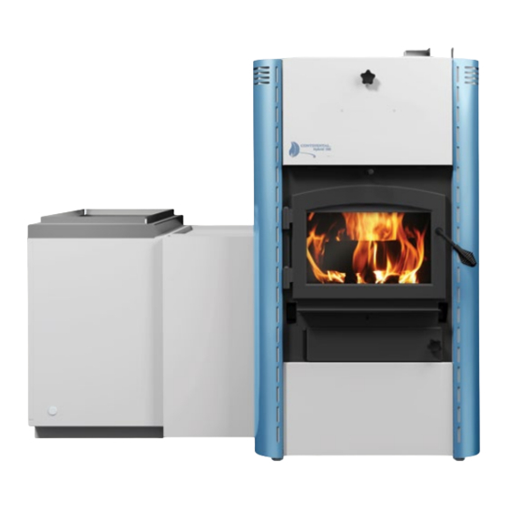
HYBRID 150/200
CHMF150/200
MULTI-FUEL FURNACES
SAFETY INFORMATION
WARNING
!
If the information in these instructions are not followed
exactly, a fi re or explosion may result causing property
damage, personal injury or death.
Please read entire manual before you install and use your
heater.
- This heater can be very hot when burning.
- Combustible materials such as fi rewood, wet clothing, etc.
placed too close can catch fi re.
- Children and pets must be kept from touching the heater when
it is hot.
- The chimney must be sound and free of cracks. Before
installing this unit, contact the local building or fi re or other
authority having jurisdiction and follow their guidelines.
- Operate only with the doors tightly closed.
- Do not use an elevated grate or otherwise raise the fi re.
- This heater is designed to burn natural wood only. Higher
effi ciencies and lower emissions generally result when
burning air dried seasoned hardwoods, as compared to
softwoods or to green or freshly cut hardwoods.
- Do not start a fi re with chemicals or fl uids such as gasoline,
engine oil, etc.
- Do not burn treated wood, coal, charcoal, coloured paper,
cardboard, solvents or garbage.
- Do not let the heater become hot enough for any part to glow
red.
Phone (705)721-1212 • Fax (705)722-6031 • www.continentalheatingandcooling.com •
$10.00
CONSUMER: SAVE THESE INSTRUCTIONS
RPT# 415-S-09b-2, 415-S-09c-8.3
Wolf Steel Ltd., 24 Napoleon Rd., Barrie, ON, L4M 0G8 Canada /
103 Miller Drive, Crittenden, Kentucky, USA, 41030
INSTALLATION
AND OPERATING
INSTRUCTIONS
Ed 2010, UL 727 9
Ed 2006, CSA B366.1-M91, CSA B140.4-04, CSA B212-00,
th
th
CSA B415.1-10.
!
WARNING
HOT GLASS WILL
CAUSE BURNS.
DO NOT TOUCH GLASS
UNTIL COOLED.
NEVER ALLOW CHILDREN
TO TOUCH GLASS.
hvac@continentalheatingandcooling.com
H1.10B
W415-1506 / A / 12.04.15
EN
FR
PG
91
Advertisement
Table of Contents

Related Manuals for Continental Heating & Cooling HYBRID 150

Summary of Contents for Continental Heating & Cooling HYBRID 150
-
Page 1: Safety Information
CERTIFIED UNDER CANADIAN AND AMERICAN NATIONAL STANDARDS: UL 391 5 Ed 2010, UL 727 9 Ed 2006, CSA B366.1-M91, CSA B140.4-04, CSA B212-00, CSA B415.1-10. RPT# 415-S-09b-2, 415-S-09c-8.3 HYBRID 150/200 CHMF150/200 MULTI-FUEL FURNACES SAFETY INFORMATION WARNING If the information in these instructions are not followed exactly, a fi... -
Page 2: Table Of Contents
TABLE OF CONTENTS INSTALLATION OVERVIEW INTRODUCTION DIMENSIONS GENERAL INSTRUCTIONS GENERAL INFORMATION 2.3.1 FEATURES 2.3.2 HEATING SPECIFICATIONS 2.3.3 ELECTRICAL SPECIFICATIONS 2.3.4 OPTIONAL MODULES 2.3.5 APPLICABLE STANDARDS 2.3.6 CALIFORNIA PROP65 RATING PLATE INFORMATION INSTALLATION PLANNING LOCATION AND CLEARANCES OUTSIDE COMBUSTION AIR UNCRATING AND ASSEMBLY CRATED UNIT CONTAINS RECOMMENDED STEP REMOVAL OF FURNACE FROM BASE OF SKID... -
Page 3: Installation Overview
DRAFT CONTROL FUEL LOADING AND BURN CYCLE 8.10 RE-LOADING THE APPLIANCE 8.11 FLASH FIRES 8.12 SMOKING 8.13 ASH REMOVAL PROCEDURES 8.14 INSPECTION OF HEAT EXCHANGERS, FLUES AND CHIMNEYS MAINTENANCE RUN-AWAY OR CHIMNEY FIRE FIRE EXTINGUISHERS AND SMOKE DETECTORS GLASS AND GASKET REPLACEMENT FIREBRICKS AND BAFFLES SELECTING WOOD GLASS REPLACEMENT... -
Page 4: Iom En
2.0 INTRODUCTION WARNING • THIS APPLIANCE IS HOT WHEN OPERATED AND CAN CAUSE SEVERE BURNS IF CONTACTED. • Do not operate appliance before reading and understanding operating instructions. Failure to operate appliance according to operating instructions could cause fi re or injury. •... -
Page 5: Dimensions
DIMENSIONS GENERAL INSTRUCTIONS WARNING BEFORE INSTALLING THIS APPLIANCE, CONTACT THE LOCAL BUILDING OR FIRE OR OTHER AUTHORITY HAVING JURISDICTION AND FOLLOW THEIR GUIDELINES. THIS APPLIANCE MUST BE INSTALLED BY A QUALIFIED INSTALLER. FOLLOW THE INSTALLATION DIRECTIONS. DO NOT OPERATE WITHOUT FULLY ASSEMBLING ALL COMPONENTS. IF THIS APPLIANCE IS NOT PROPERLY INSTALLED, A HOUSE FIRE MAY RESULT. - Page 6 AIR FLOW CIRCULATION AND HEAT TRANSFER COMBUSTION AIR FLOW W415-1506 / A / 12.04.15...
-
Page 7: General Information
GENERAL INFORMATION 2.3.1 FEATURES • Maximum log length of 24" (610mm) (CHMF150), • Outside air for combustion and 30” (762mm) (CHMF200) • Choice of glass door for radiant heat through front • Long burn time - up to 12 hours (CHMF150), 18 of furnace, or solid door to provide more heating hours (CHMF200) through exchange surfaces... -
Page 8: Installation Planning
3.0 INSTALLATION PLANNING WEAR GLOVES AND SAFETY GLASSES FOR PROTECTION. KEEP HAND TOOLS IN GOOD CONDITION, SHARPEN CUTTING EDGES AND MAKE SURE TOOL HANDLES ARE SECURE. DO NOT MAKESHIFT COMPROMISES DURING INSTALLATION. DO NOT BLOCK OR RESTRICT AIR. DO NOT IMPEDE AIR MOVEMENT ZONES MARKED “CLEARANCE TO COMBUSTIBLES”. H3.32 LOCATION AND CLEARANCES FOR C/HMF150 DO NOT INSTALL INTO ANY AREA HAVING A HEIGHT LESS THAN 6 FEET 3 INCHES... - Page 9 Insulating the intake liners is recommended in colder climates to prevent condensation from occurring. The 4" (102mm) inlet can also draw combustion air from the room provided adequate make up air is available. Fresh air makeup for the oil furnaces must follow criteria set in installation standard CSA B139-09 "Installation Code For Oil Burning Equipment", and installed by a certifi...
-
Page 10: Uncrating And Assembly
4.0 UNCRATING AND ASSEMBLY CRATED UNIT CONTAINS • Primary Air Control Kit • Main / Electrical Harness Kit (1 pc.) • Bricks (37 pcs. CHMF150, 53 pcs. CHMF200) • Baffl es (2 pcs.) • Secondary Air Tubes (4 pcs. CHMF150, 5 pcs. CHMF200) •... -
Page 11: Removal Of Furnace From Base Of Skid
REMOVAL OF FURNACE FROM BASE OF SKID FURNACE BASE LOOSEN OFF LOCK NUT ADJUSTMENT FOOT SECURING BRACKET REMOVE LAG BOLT BASE SKID CAUTION HIGH CENTRE OF GRAVITY! USE EXTREME CAUTION TO AVOID TOPPLING OF THE FURNACE "CRUSH HAZARD"! STEP #1: Push the furnace to one side until close to the weight tipping the skid. -
Page 12: Configuring Chmf150/200 As Left Or Right "Return Air" (Ra)
CONFIGURING CHMF150/200 AS LEFT OR RIGHT "RETURN AIR” (RA) The CHMF150/200 can be installed upstream with the return air, (also supply air from pre existing furnace "add on" confi guration), entering from the left or right hand sides of the furnace. The RETURN AIR RETURN AIR CHMF150/200 comes confi... -
Page 13: Mounting Primary Air Control
MOUNTING PRIMARY AIR CONTROL IMPORTANT: This step must follow the plenum installation in Section 6.0. The plenum is not shown in diagrams below, for clarity purposes. Location of the Primary Air Control in left and right RA. RIGHT HAND RA LEFT HAND RA 1. -
Page 14: Secondary Air Tubes
2. Assemble the control box as illustrated using the fasteners supplied. Main air control box is secured with (3) screws into the rear panel and (1) through the inside fl ange of the main box and into the furnace top. 3. - Page 15 STEP #2 ○ Once the secondary tube has been pushed completely to the right and the key has engaged the keyway, insert a hitch pin into the left most clearance hole of the secondary tube. STEP #3 ○ Carefully pivot the compressed vermiculite baffl es up onto the rear secondary air tubes as illustrated. En- sure that the top baffl...
-
Page 16: Door Handle Installation
DOOR HANDLE INSTALLATION WARNING BURNING YOUR APPLIANCE WITH THE DOORS OPEN OR AJAR CREATES A FIRE HAZARD THAT MAY RESULT IN A HOUSE AND OR CHIMNEY FIRE. DO NOT STRIKE OR SLAM DOOR. NEVER REMOVE THE DOOR WHEN THE APPLIANCE IS HOT. H3.1 NOTE: DOOR MAY NOT BE AS ILLUSTRATED... -
Page 17: Configuration Of Left And Right Return Air With Other Hybrid Modules
5.0 CONFIGURATION OF LEFT AND RIGHT RETURN AIR WITH OTHER HYBRID MODULES Hybrid CHMF150/200 as a "Add On" to existing furnace (see Section 5.1). In this application the HMFK-BMP50 blower module is not used. Hybrid CHMF150/200 as a Stand Alone Wood Furnace, (see Section 5.2). -
Page 18: Hybrid Chmf150/200 As A "Add On" To Existing Furnace
HYBRID CHMF150/200 AS A "ADD ON" TO EXISTING FURNACE THE INSTALLATION OF THE FURNACE MUST BE DONE IN ACCORDANCE WITH RULES OF AUTHORITIES HAVING JURISDICTION AND THE CAN / CSA B365-01 (R2006) STANDARD FOR SOLID FUEL BURNING APPLIANCES AND EQUIPMENT. THE HMF/CHMF 150/200 WOOD FURNACES ARE NOT INTENDED FOR USE AS AN “ADD ON”... - Page 19 • the equipment shall be installed in accordance with the instructions of the original furnace manufacturer and in a manner acceptable to the regulatory authority by qualifi ed personnel. The operation of the original furnace must be verifi ed for acceptable operation before and after installation of the "Add On".
- Page 20 INSTALLATION OF "ADD-ON" CONFIGURATION REQUIRES FIELD WIRING BY A CERTIFIED ELECTRICIAN. ALL WIRING TO CONFORM TO CSA 22.1. H3.40 Install wood limit switch: • Locate and drill a 7/8" hole in the side of the plenum on the same side as the location of the CHMF150/200 main wire harness, as illustrated.
- Page 21 • Secure all fl ag connectors to switch terminals, and route ground line to switch chassis. • Confi rm the set points by checking to see if the straight edge of the pointer indicates the correct temperature listed. WOOD FAN/LIMIT SET POINTS FAN ON SET POINT LEVER FAN OFF SET POINT LEVER CAUTION...
- Page 22 LOWER ELECTRICAL BOX - MAIN HARNESS CHMF150/200 “B” HARNESS CONNECTOR LINES 12 & N TO ENGAGE COIL CONTROL WIRE FOR ON RELAY BLOWER CONTROL ON ORIGINAL RELAY BLOCK FURNACE FIELD SUPPLIED IN INSTALLATION “ADD ON ” MODULE KIT NOTE - Instructions and specifi cations to be included in kit for: a) For ECM motor in original furnace •...
-
Page 23: Hybrid Chmf150/200 As A "Stand Alone" Wood Furnace
HYBRID CHMF150/200 AS A “STAND ALONE” WOOD FURNACE REQUIRED COMPONENTS: • CHMF150/200 Hybrid Furnace • HMFK-BMP50-1 Blower Box Module • HMFK-SOLID or HMFK-GLASS Door Kit STEPS: Completely assemble CHMF150/200 in required left or right hand "RA" confi guration as required. STEP #1 - #4 Follow Steps 1 to 4 from SECTION 5.1 - HYBRID CHMF150/200 AS A "ADD ON"... - Page 24 STEP #8 ○ Remove the access panel from the rear of the blower box module. ○ Route the harness from the rear of the lower electrical box of the main electric harness to access the hole on the side of blower box. ACCESS ○...
-
Page 25: Hybrid Chmf150/200 As A Combination "Wood/Oil" Furnace
HYBRID CHMF150/200 AS A COMBINATION “WOOD/OIL” FURNACE THE INSTALLATION OF THE WOOD OIL COMBINATION FURNACE MUST BE DONE IN ACCORDANCE WITH THE RULES OF THE AUTHORITIES HAVING JURISDICTION AND THE CAN / CSA B139-09 STANDARD FOR OIL BURNING HEATING APPLIANCES. H3.43 REQUIRED COMPONENTS: •... - Page 26 STEP #12 ○ Insert the stainless steel oil furnace combustion chamber/heat exchanger HMFK-CMBCH-1 (CHMF150) or HMFK-CCH200 (CHMF200), into the lower cavity of HMF150/200 body (see diagrams). Ensure the heat exchanger is on the same side as the blower. AIR FLOW DIRECTION FROM BLOWER MODULE AIR FLOW...
- Page 27 ○ Locate fl ange gasket over bolts of oil furnace mounting fl ange, prior to placing bottom front cover up to mounting fl ange. ○ Align mounting bolts on fl ange align with clearance holes in bottom front panel when panel loosely fi t in fi nal position. ○...
- Page 28 ALL 115V ELECTRICAL PRE ASSEMBLED HARNESSES MUST BE INSTALLED AS PER INSTRUCTIONS. NO 115V ELECTRIC CIRCUIT HARNESS OR FIELD WIRING MAY PASS THROUGH CLEARANCE SPACE BETWEEN HMF150/200 FURNACE BOTTOM AND FLOOR. FAILURE TO COMPLY MAY RESULT IN ELECTRIC SHOCK, FIRE, PROPERTY DAMAGE OR PERSONAL INJURY.
- Page 29 STEP #16 THE MOUNTING LOCATION AND MOUNTING BRACKET FOR THE OIL LIMIT SWITCH ARE NOT THE SAME FOR THE HMF150 AND HMF200. STRICTLY ADHERE TO THE INSTRUCTION SET PERTAIN- ING TO THE MODEL BEING INSTALLED. FAILING TO DO SO COULD RESULT IN POOR OPERATION, PROPERTY DAMAGE AND PERSONAL INJURY.
- Page 30 CHMF200 OIL LIMIT & OIL LIMIT & FURNACE FURNACE MOUNTING MOUNTING FLUE FLUE BRACKET BRACKET OIL LIMIT HARNESS OIL LIMIT BLOWER MODULE HARNESS HARNESS BLOWER MODULE HARNESS LEFT HAND RA CONFIGURATION RIGHT HAND RA CONFIGURATION FIGURE A - OIL FAN/LIMIT WIRING OIL FAN/LIMIT SET POINTS FIGURE B - FAN OFF SET...
- Page 31 NOTE Clearance holes in the 5" (127mm) fl ue plate cover may not align perfectly with the original pilot holes in rear face of the rear panel. There is adequate clearance between the oil furnace fl ue and the fl ue exit hole in the rear panel to accommodate any misalignment between the two caused by standard fabrication tolerances.
- Page 32 STEP #18 ALL INSTALLATION AND MAINTENANCE MUST BE PERFORMED BY A QUALIFIED/LICENSED IN- STALLER. INCORRECT INSTALLATION, ADJUSTMENT, AND USE OF THE OIL BURNER COULD RE- SULT IN SEVERE PERSONAL INJURY, DEATH OR SUBSTANTIAL PROPERTY DAMAGE FROM FIRE, CARBON MONOXIDE POISONING, SOOT OR EXPLOSION. H3.48 Connecting fuel to the oil module burner: ○...
-
Page 33: Hybrid Chmf150/200 As A Combination "Wood/Electric" Furnace
HYBRID CHMF150/200 AS A COMBINATION “WOOD/ELECTRIC” FURNACE REQUIRED COMPONENTS: • CHMF150/200 Hybrid Furnace • HMFK-BMP50 Blower Box Module • HMFK-EF15, -EF18, -EF20, -EF25 Electric Furnace Module (HMFK-EF25 is available for the CHMF200 only) • HMFK-SOLID or HMFK-GLASS Door Kit STEPS #1 - #4 Follow Steps 1 to 4 from SECTION 5.1 - HYBRID CHMF150/200 AS AN "ADD ON"... - Page 34 STEP #10 ○ Lift open side of electric furnace module so as to allow mounting fl ange on bottom edge of electric fur- nace box to clear top edge of retaining bracket fastened to the lower edge of the rectangular window, the furnace side.
- Page 35 STEP #12 ○ See SECTION 6.0 - PLENUM AND VENTING INSTALLATION. STEP #13 Fan Contact Wiring: ○ Take the wire harness (red, red, green) supplied in the Electric Furnace Kit and feed one end through the front electrical knock out in the base of the electric furnace module and secure the conduit fi tting with the locknut.
-
Page 36: Hybrid Chmf150/200 As A "Wood/Oil/Electric" Furnace
STEP #14 ○ See SECTION 8.0 - OPERATING INSTRUCTIONS. HYBRID CHMF150/200 AS A “WOOD/OIL/ELECTRIC” FURNACE REQUIRED COMPONENTS: • HMFK-CMBCH-1 (HMF150) or HMFK-CCH200 • CHMF150/200 Hybrid Furnace (CHMF200) Oil Combustion/Heat Exchanger • HMFK-BMP50 Blower Box Module • HMFK-WMO WMO Thermal Safety Switch •... -
Page 37: Plenum And Venting Installation/Clearance To Combustible Materials
6.0 PLENUM AND VENTING INSTALLATION/ CLEARANCE TO COMBUSTIBLE MATERIALS ALL PLENUM DUCTING AND VENTING INSTALLATION MUST CONFORM WITH CAN/CSA B365-01, CSA B139-09, AND NFPA 211. ALWAYS CHECK LOCAL BUILDING AND FIRE CODES , AND AUTHORI- TIES HAVING JURISDICTION. ALL PLENUM, DUCTING AND VENTING MUST BE INSTALLED BY A QUALIFIED INSTALLER. DO NOT USE MAKESHIFT COMPROMISES DURING INSTALLATION. -
Page 38: Venting Configuration For Wood/Oil Combination Furnace
THE USE OF A BAROMETRIC DAMPER ON A WOOD OR WOOD/OIL APPLIANCE CAN HAVE THE FOLLOWING CONSEQUENCES: 1. DILLUTION AIR ENTERING THROUGH THE BAROMETRIC DAMPER MAY PREMATURELY COOL EXHAUST PRODUCTS CREATING EXCESS CREOSOTE DEPOSITS INSIDE THE CHIMNEY LEADING TO A CHIMNEY FIRE HAZARD. 2. - Page 39 VENTING CLEARANCE TO COMBUSTIBLES AND SERVICE CLEARANCES LEFT HAND RA CONFIGURATION (REAR VIEW) LEFT HAND RA CONFIGURATION (SIDE VIEW BLOWER MODULE) 18” WOOD, WOOD/OIL FLUE (457mm) 18" (457mm) 18" (457mm) MAX 16" (406mm) WOOD, WOOD/OIL FLUE 9" (229mm) 9” 14" (356mm) (229mm) 14"...
-
Page 40: General Plenum And Ducting - Minimum Clearance To Combustibles
GENERAL PLENUM AND DUCTING - MINIMUM CLEARANCE TO COMBUSTIBLES All plenum and ducting clearances must satisfy specifi cation set forth in CAN/CSA-B365-10 and NFPA211. CLEARANCE SECTION IMPORTANT: COMBUSTIBLES Minimum ceiling heights required: • CHMF150 6ft 3in (1.9m) 6" (152mm) * 6"... -
Page 41: Chmf200 Shielding Specifications
6.3.2 CHMF200 SHIELDING SPECIFICATIONS ○ Shield must be constructed of sheet metal with a minimum thickness of 26 gauge. ○ Shield to be spaced out from combustible surface a minimum of 1" (25mm), using non-combustible spac- ers (air gap between combustible surface and shield must be maintained). ○... -
Page 42: Flue Configuration For "Add On" Furnace Configuration
FLUE CONFIGURATION FOR "ADD ON" FURNACE CONFIGURATION Separate chimneys are required when connecting the CHMF150/200 to a natural gas or propane furnace. UNDER NO CONDITIONS MAY A SOLID FUEL BURNING APPLIANCE SHARE A CHIMNEY THAT VENTS NATURAL GAS OR PROPANE EXHAUST. DO NOT USE MAKESHIFT COMPROMISES DURING INSTALLATION. -
Page 43: Measuring Draft
6.4.2 MEASURING DRAFT Using a manometer with appropriate scale range connect testing tube between manometer and chimney connector. End of testing tube should be inserted in chimney connector so approximately 1” (25mm) of tube protrudes into and perpendicular to exhaust stream. This measurement shall be taken approximately 12” (305mm) above elbow/T attached to the furnace fl... -
Page 44: Ember Stop
SAMPLES OF ALLOWABLE PLENUM/DUCTING ARRANGEMENTS CONTINUED ALLOWABLE PROHIBITED “ADD ON” EXISTING WOOD FURNACE (downflow FURNACE “ADD ON” or counterflow) or counte EXISTING WOOD FURNACE FURNACE HORIZONTAL EXISTING FURNACE DIVIDER “ADD ON” WOOD “ADD ON” FURNACE EXISTING WOOD FURNACE FURNACE “ADD ON” WOOD “ADD ON”... -
Page 45: Connecting A Chmf Furnace System To Air Conditioning
CONNECTING A CHMF FURNACE SYSTEM TO AIR CONDITIONING SUGGESTED KIT REQUIRED KIT HMFK-AC1 • Contains limit switches and damper HMFK-AC2 • Contains fi eld install relay blocks position/warning labels for interlocking and wiring required when using plenum damper controls to wood HMFK-BMP50(-1) Blower Module in furnace combustion air controls. -
Page 46: Seasonal Damper Positions
EXAMPLE OF AN ACCEPTABLE BYPASS DESIGN RETURN EVAPORATOR SEASONAL PLENUM COIL POSTION DAMPER LOCATION SUPPLY PLENUM BYPASS PLENUM HMFK-BMP50 BLOWER MODULE OR HMFK-GT TRANSITION KIT (HMFK- GT WITH NPV060 GAS FURNACE SHOWN) SEASONAL DAMPER LOCATION 6.7.1 SEASONAL DAMPER POSITIONS DAMPER ORIENTATION “WINTER MODE” DAMPER ORIENTATION “SUMMER MODE”... -
Page 47: Dimensional Considerations For Bypass Duct
6.7.2 DIMENSIONAL CONSIDERATIONS FOR BYPASS DUCT DIMENSION TO SUIT INSERTION DIMENSION TO SUIT DEPTH OF EVAPORATOR COIL INSERTION WIDTH OF 20.0” (508mm) MINIMUM EVAPORATOR COIL MAINTAIN 6.0” (152mm) MINIMUM BETWEEN BYPASS PLENUM AND MAINTAIN 1/2 DIMENSION “A” HMFK-BMP50(-1)/HMFK-GT MINIMUM BETWEEN BYPASS PLENUM AND WOOD FURNACE DIMENSION “A”... - Page 48 Example shows part of the control wiring Example shows part of the control wiring for wood, wood/electric, wood/oil, or for wood, wood/electric, wood/oil, or WOOD FURNACE wood/oil electric with air conditioning wood/oil electric with air conditioning TERMINAL STRIP “WINTER” LIMIT confi...
-
Page 49: Electrical Connections And Schematics
7.0 ELECTRICAL CONNECTIONS AND SCHEMATICS ALL ELECTRICAL WIRING AND CONNECTIONS MUST BE DONE BY A QUALIFIED ELECTRICIAN. THE ELECTRICAL INSTALLATION MUST SATISFY ALL RELEVANT ASPECTS OF CSA 22.1 AND IN PARTICULAR CAN/CSA-222.2 NO.0-M91, NO.3-M1988, NO. 23.1-M1986. ALL WIRING BRINGING 120V OR GREATER TO THE HMF150 AND ITS MODULES, SHALL BE AS SPECIFIED IN ELECTRICAL CODE BUT MUST HAVE WIRE INSULATION VALUE OF NO LESS THAN 90°C. -
Page 50: Selecting Air Conditioning Blower Speeds
ELECTRIC FURNACE HARNESS FOR WOOD/ FOR WOOD, ELECTRIC FURNACE HARNESS (NOT APPLICABLE FOR “WOOD/OIL” FURNACE) (NOT APPLICABLE FOR “WOOD ONLY” FURNACE) OIL, WOOD/ WOOD/ELECTRIC OIL/ELECTRIC COMBINATIONS COMBINATIONS (CHMF150) (CHMF150) (15,18,20 KW) (15,18,20 KW) TERMINAL BLOCK IN BLOWER TERMINAL BLOCK IN BLOWER MODULE MODULE CHMF150... - Page 51 AIR SPEEDS AVAILABLE WITH HMFK-BMP50-1: POWER FOR AIR CONDITIONING BLOWER OPERATION. TERMINATE ON APPROPRIATE MOTOR SPEED. SEE SECTION 7.3 FOR FURNACE SPEED SELECTIONS TERMINAL BLOCK IN BLOWER AVERAGE AIR MODULE SPEEDS BASED ON SUPPLY PLENUM STATIC PRESSURE OF 0.2” W.C.: 1000 CFM RED..
-
Page 52: Electric Schematics - General Harness Layout
ELECTRIC SCHEMATICS - GENERAL HARNESS LAYOUT 7.4.1 GENERAL HARNESS LAYOUT: ALL CONFIGURATIONS WOOD FURNACE FAN SPEED/HIGH LIMIT SWITCH NOTE: MOVE WIRE #5 TO TERMINAL #6 FOR “ADD ON”, “STAND ALONE” WOOD FURNACE, AND “WOOD/ELECTRIC” CONFIGURATIONS LIMIT 120 VAC POWER L1 N LINE OIL FURNACE FAN SPEED/HIGH LIMIT SWITCH... -
Page 53: General Harness Layout: Wood/"Add On" Configuration Including Continental Wood/Gas Combo
7.4.2 GENERAL HARNESS LAYOUT: WOOD/”ADD ON” CONFIGURATION INCLUDING CONTINENTAL WOOD/GAS COMBO WOOD FURNACE FAN SPEED/HIGH LIMIT SWITCH NOTE: MOVE WIRE #5 TO TERMINAL #6 FOR “ADD ON”, “STAND ALONE” WOOD FURNACE, AND “WOOD/ELECTRIC” CONFIGURATIONS LIMIT 120 VAC POWER L1 N G LINE 4 4 5 9 10 11 12 12 13 14 15 16 16... -
Page 54: General Harness Layout: Wood Configuration
7.4.3 GENERAL HARNESS LAYOUT: WOOD CONFIGURATION WOOD FURNACE FAN SPEED/HIGH LIMIT SWITCH NOTE: MOVE WIRE #5 TO TERMINAL #6 FOR “ADD ON”, “STAND ALONE” WOOD FURNACE, AND “WOOD/ELECTRIC” CONFIGURATIONS LIMIT 120 VAC POWER L1 N G LINE 9 10 11 12 12 13 14 15 16 16 LOWER JUNCTION BOX HMFK-BMP50-1 BLOWER BOX BLOWER... -
Page 55: General Harness Layout: Wood/Oil Configuration
7.4.4 GENERAL HARNESS LAYOUT: WOOD/OIL CONFIGURATION WOOD FURNACE FAN SPEED/HIGH LIMIT SWITCH LIMIT 120 VAC POWER L1 N G LINE OIL FURNACE FAN SPEED/HIGH LIMIT SWITCH 9 10 11 12 12 13 14 15 16 16 LIMIT LOWER JUNCTION BOX LINE (L1) WHITE... -
Page 56: General Harness Layout: Wood/Electric Configuration
7.4.5 GENERAL HARNESS LAYOUT: WOOD/ELECTRIC CONFIGURATION WOOD FURNACE FAN SPEED/HIGH LIMIT SWITCH NOTE: MOVE WIRE #5 TO TERMINAL #6 FOR “ADD ON”, “STAND ALONE” WOOD FURNACE, AND “WOOD/ELECTRIC” CONFIGURATIONS LIMIT 120 VAC POWER L1 N G LINE 9 10 11 12 12 13 14 15 16 16 LOWER JUNCTION BOX HMFK-BMP50-1 BLOWER BOX BLOWER... -
Page 57: General Harness Layout: Wood/Oil/Electric Configuration
7.4.6 GENERAL HARNESS LAYOUT: WOOD/OIL/ELECTRIC CONFIGURATION WOOD FURNACE FAN SPEED/HIGH LIMIT SWITCH NOTE: MOVE WIRE #5 TO TERMINAL #6 FOR “ADD ON”, “STAND ALONE” WOOD FURNACE, AND “WOOD/ELECTRIC” CONFIGURATIONS LIMIT 120 VAC POWER L1 N G LINE OIL FURNACE FAN SPEED/HIGH LIMIT SWITCH 9 10 11 12 12 13 14 15 16 16 LIMIT LOWER JUNCTION BOX... -
Page 58: Electric Schematics - Control Wiring Without Air Conditioning
ELECTRIC SCHEMATICS - CONTROL WIRING WITHOUT AIR CONDITIONING 7.5.1 CONTROL WIRING WITHOUT AIR CONDITIONING: ALL CONFIGURATIONS W415-1506 / A / 12.04.15... -
Page 59: Control Wiring Without Air Conditioning: "Add On" Furnace Configuration
7.5.2 CONTROL WIRING WITHOUT AIR CONDITIONING: “ADD ON” FURNACE CONFIGURATION W415-1506 / A / 12.04.15... -
Page 60: Control Wiring Without Air Conditioning: Wood Furnace Only Configuration
7.5.3 CONTROL WIRING WITHOUT AIR CONDITIONING: WOOD FURNACE ONLY CONFIGURATION W415-1506 / A / 12.04.15... -
Page 61: Control Wiring Without Air Conditioning: Oil Furnace Configuration
7.5.4 CONTROL WIRING WITHOUT AIR CONDITIONING: OIL FURNACE CONFIGURATION W415-1506 / A / 12.04.15... -
Page 62: Control Wiring Without Air Conditioning: Electric Furnace Configuration
7.5.5 CONTROL WIRING WITHOUT AIR CONDITIONING: ELECTRIC FURNACE CONFIGURATION W415-1506 / A / 12.04.15... -
Page 63: Control Wiring Without Air Conditioning: Oil/Electric Furnace Configuration
7.5.6 CONTROL WIRING WITHOUT AIR CONDITIONING: OIL/ELECTRIC FURNACE CONFIGURATION W415-1506 / A / 12.04.15... -
Page 64: Electric Schematics - Control Wiring With Air Conditioning
ELECTRIC SCHEMATICS - CONTROL WIRING WITH AIR CONDITIONING 7.6.1 CONTROL WIRING WITH AIR CONDITIONING: “ADD ON” FURNACE CONFIGURATION W415-1506 / A / 12.04.15... -
Page 65: Control Wiring With Air Conditioning: Wood Furnace Only Configuration
7.6.2 CONTROL WIRING WITH AIR CONDITIONING: WOOD FURNACE ONLY CONFIGURATION W415-1506 / A / 12.04.15... -
Page 66: Control Wiring With Air Conditioning: Wood/Oil Furnace Configuration
7.6.3 CONTROL WIRING WITH AIR CONDITIONING: WOOD/OIL FURNACE CONFIGURATION W415-1506 / A / 12.04.15... -
Page 67: Control Wiring With Air Conditioning: Wood/Electric Furnace Configuration
7.6.4 CONTROL WIRING WITH AIR CONDITIONING: WOOD/ELECTRIC FURNACE CONFIGURATION W415-1506 / A / 12.04.15... -
Page 68: Control Wiring With Air Conditioning: Wood/Oil/Electric Furnace Configuration
7.6.5 CONTROL WIRING WITH AIR CONDITIONING: WOOD/OIL/ELECTRIC FURNACE CONFIGURATION W415-1506 / A / 12.04.15... -
Page 69: Electric Schematics - Main Control Harness
ELECTRIC SCHEMATICS - MAIN CONTROL HARNESS L1 - TERMINAL 120 VAC GROUND N - TERMINAL FIELD WIRE POWER TO LOWER G - TERMINAL JUNCTION BOX TO WOOD HIGH LIMIT SWITCH TO SUMMER SWITCH MALE CONNECTOR FEMALE CONNECTOR FEMALE CONNECTOR WIRE SIDE VIEW WIRE SIDE VIEW WIRE SIDE VIEW G - GREEN... - Page 70 W415-1506 / A / 12.04.15...
-
Page 71: General Operating Instructions
8.0 GENERAL OPERATING INSTRUCTIONS OPERATION FOR HIGHER EFFIECIENCY AND LOWER EMISSIONS This appliance complies with Step 1.0 For Warm Air Furnaces Under The New Source Performance Standards (NSPS), published by the EPA in the Federal Register on March 16, 2015. This appliance has been certifi... -
Page 72: Control System - Wood Furnace
Carbon monoxide is a colourless, odourless, and tasteless gas that is toxic when inhaled, and can be fatal depending on concentration levels and exposure time. Note that although carbon monoxide will be present in poor combustion process that creates smoke (as described above), it is not necessary for smoke to be pres- ent while high levels of carbon monoxide are being created. -
Page 73: Power Outage Operation
8.3.1 POWER OUTAGE OPERATION HIGH TEMPERATURES CAN BUILD IN THE DUCT WORK, TO ENSURE AIR CIRCULATING IN A GRAV- ITY METHOD REMOVE AIR FILTER FROM FURNACE. ENSURE ALL SUPPLY AND RETURN AIR GRILLS ARE FREE FROM HOUSEHOLD OBJECTS OR DEBRIS, AND ENSURE ANY MANUAL DAMP- ERS IN THE DUCT NETWORK ARE FIXED IN A FULL OPEN CONDITION. -
Page 74: Control System - Summer Fan/Continuous Fan/Hrv's
CONTROL SYSTEM - SUMMER FAN/CONTINUOUS FAN/HRV’S A summer fan switch has been added to the main electric control box. This will provide low speed air circula- tion during the summer time when the furnace is not being used. Depress rocker switch to “Summer Fan” position, the switch will light and the fan will run. -
Page 75: Starting A Fire
STARTING A FIRE ALWAYS OPERATE THIS APPLIANCE WITH THE FIRE BOX DOOR CLOSED AND LATCHED EXCEPT DURING START UP AND RE-FUELING. ALWAYS WEAR GLOVES TO PREVENT INJURY. DO NOT LEAVE THE FIRE UNATTENDED WHEN THE DOOR IS UNLATCHED AS UNSTABLE WOOD COULD FALL OUT OF THE FIRE CHAMBER CREATING A FIRE HAZARD TO YOUR HOME. -
Page 76: Draft Control
Never use gasoline, gasoline-type lantern fuel, kerosene, charcoal lighter fl uid, or similar liquids to start or freshen-up a fi re in this appliance. Keep all such liquids well away from the appliance while it is in use. If using a fi... -
Page 77: Fuel Loading And Burn Cycle
draft may cause an excessive temperature in the appliance, glowing red appliance parts or an uncontrollable burn which can all lead to a chimney NOTE fi re or a permanent damage to the appliance. Differences in the chimney Roll up some newspaper, light it and place it near the appliance fl ue until height and draft may lower the chimney begins to draw. -
Page 78: Flash Fires
8.10 RE-LOADING THE APPLIANCE When refuelling open the bypass damper and then slowly open the door to prevent smoke spillage. Use a pair of long appliance gloves when feeding the fi re. Keep a small steel shovel nearby to use as a poker and to remove ashes. - Page 79 8.13 ASH REMOVAL PROCEDURES ASH REMOVAL DOOR SHALL ALWAYS BE TIGHTLY CLOSED EXCEPT WHEN COAL BED IS EXTIN- GUISHED AND ASH ARE BEING REMOVED FROM FURNACE. OPEN OR POORLY SEALED ASH REMOVAL DOORS DURING NORMAL OPERATION OF THE FUR- NACE CAN CAUSE A FORGE AFFECT ON THE FUEL LOAD AND CAUSE THE FURNACE TO OVER FIRE.
-
Page 80: Glass And Gasket Replacement
9.0 MAINTENANCE RUN-AWAY OR CHIMNEY FIRE WARNING A CHIMNEY FIRE CAN PERMANENTLY DAMAGE YOUR CHIMNEY SYSTEM. THIS DAMAGE CAN ONLY BE REPAIRED BY REPLACING THE DAMAGED COMPONENT PARTS. CHIMNEY FIRES ARE NOT COVERED BY THE LIFETIME LIMITED WARRANTY. H3.74 Run-away fi res can be the result of FOUR major factors: CAUSES: 1. -
Page 81: Selecting Wood
FIREBRICKS AND BAFFLES Inspect and replace all broken fi rebricks ad baffl es. CHMF150: CHMF200: OPERATION OF THE APPLIANCE WITHOUT THE BAFFLES OR FIREBRICKS WILL DAMAGE THE APPLIANCE, CHIMNEY AND THE SURROUNDING ENCLOSURE. H3.76 SELECTING WOOD WARNING THIS APPLIANCE IS DESIGNED TO BURN NATURAL WOOD ONLY. DO NOT BURN TREATED WOOD, COAL, CHARCOAL, COLOURED PAPER, CARDBOARD, SOLVENTS OR GARBAGE. -
Page 82: Glass Replacement
Burn only dry, clean unpainted wood that has been seasoned. It produces more heat and less soot or creosote. Freshly cut wood contains about 50% moisture while after proper seasoning only about 20% of the water remains. As wood is burned, this water boils off consuming energy that should be used in heating. -
Page 83: Creosote Formation And Removal
INSULATION INSERT REPLACEMENT At the end of each burning season inspect the fi re box door fi bre insulation and guard for deterioration or breakage. Replace if necessary. 1. When the appliance is cool, open the door and place the door frame down careful not to scratch the paint. -
Page 84: Maintenance Of The Exchangers
9.8.1 MAINTENANCE OF THE EXCHANGERS The three heat exchanger pipes should be inspected regularly during the burning season. Easy access is provided (without the use of tools); simply unscrew the common knob on the exchanger access door, Figure 1. Before cleaning the three exchanger pipes move the upper baffles of the combustion chamber forward (see Figure 2), and fully open the bypass damper. -
Page 85: Blower Motor Lubrication
FILTERS The furnace must not be operated without fi lters. In order to effi ciently and safely operate a slow combustion heating system, you have to ensure a regular maintenance. This means that the chimney, the joints and the fl ue must be kept in good condition and the air fi lters must be replaced regularly; use standard capacity pleated air fi... - Page 86 10.0 REPLACEMENTS Contact your dealer or the factory for questions concerning prices and policies on replacement parts. Normally all parts can be ordered through your Authorized dealer / distributor. WARNING FOR WARRANTY REPLACEMENT PARTS, A PHOTOCOPY OF THE ORIGINAL INVOICE WILL BE REQUIRED TO HONOUR THE CLAIM. FAILURE TO POSITION THE PARTS When ordering replacement parts always give the following information: IN ACCORDANCE WITH THIS...
-
Page 87: Trouble Shooting Guide
11.0 TROUBLE SHOOTING GUIDE WARNING TURN OFF THE ELECTRICAL POWER BEFORE SERVICING THE APPLIANCE. APPLIANCE MAY BE HOT, DO NOT SERVICE UNTIL APPLIANCE HAS COOLED. DO NOT USE ABRASIVE CLEANERS. SYMPTOM PROBLEM TEST SOLUTION - Burn a piece of newspaper to establish a draft. Smoke enters the Cold air blockage in chimney. - Page 88 12.0 WARRANTY CONTINENTAL® products are manufactured under the strict Standard of the world recognized ISO 9001 : 2008 Quality Assurance Certifi cate. CONTINENTAL® products are designed with superior components and materials, assembled by trained craftsmen who take great pride in their work. The complete appliance is again thoroughly inspected by a qualifi ed technician before packaging to ensure that you, the customer, receives the quality product that you expect from CONTINENTAL®.
- Page 89 13.0 SERVICE HISTORY 43.1 W415-1506 / A / 12.04.15...
- Page 90 14.0 NOTES 44.1 W415-1506 / A / 12.04.15...
Need help?
Do you have a question about the HYBRID 150 and is the answer not in the manual?
Questions and answers
Can I add on a heat pump instead of an AC coil to the continental hybrid 200 furnace??