Table of Contents
Advertisement
Chapter 1
Getting Started
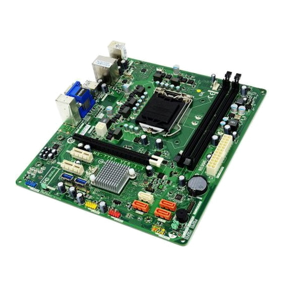
Thank you for choosing the 7797 v1.X series Micro-ATX
mainboard. The Series mainboards are based on Intel
®
B75 chipset for optimal system efficiency. Designed to
fit the advanced Intel
LGA1155 processor, the Series
®
mainboards deliver a high performance and professional
desktop platform solution.
Advertisement
Table of Contents

Related Manuals for MSI MS7797


Summary of Contents for MSI MS7797
-
Page 1: Getting Started
Chapter 1 Getting Started Thank you for choosing the 7797 v1.X series Micro-ATX mainboard. The Series mainboards are based on Intel ® B75 chipset for optimal system efficiency. Designed to fit the advanced Intel LGA1155 processor, the Series ® mainboards deliver a high performance and professional desktop platform solution. -
Page 2: Assembly Precautions
Getting Started Assembly Precautions ■ The components included in this package are prone to damage from electrostatic discharge (ESD). Please adhere to the following instructions to ensure successful computer assembly. ■ Always turn off the power supply and unplug the power cord from the power outlet before installing or removing any computer component. -
Page 3: Mainboard Specifications
7797 Mainboard Specifications Processor Support ■ Support 3 Generation Intel Core™ i7/ Core™ i5/ Core™ i3/ Pentium / Celeron ® ® ® Processors for LGA 1155 socket Chipset ■ Intel B75 chipset ® Supports Intel ® Memory Support ■ 2x DDR3 DIMMs support DDR3 1600/ 1333/ 1066 DRAM (16GB Max.) ■... -
Page 4: Connectors Quick Guide
Getting Started Connectors Quick Guide DDR3 ATX_CPU1 CPU_FAN1 Back Panel ATX_POWER1 PCIEX16_1 SATA1 PCIEX1_1 SATA2~4 PCIEX1_2 CLR_PWD1 ME_LOCK1 F_AUDIO1 F_USB30_1 F_PANEL1 F_USB30_2 F_USB2 JBAT1 F_USB1... -
Page 5: Table Of Contents
7797 Connectors Reference Guide Port Name Port Type Page Back Panel ATX_CPU1 ATX 4-pin Power Connector 1-13 ATX_POWER1 ATX 24-pin Power Connector 1-13 CLR_PWD1 Clear BIOS Password Jumper 1-22 CPU & Cooler Installation CPU_FAN1 Fan Power Connector 1-18 DDR3 DDR3 DIMMs 1-14 F_AUDIO1 Front Panel Audio Connector... -
Page 6: Back Panel Quick Guide
Getting Started Back Panel Quick Guide VGA Port Line-In Mouse USB 3.0 Port USB 2.0 Port Line-Out Keyboard USB 2.0 Port HDMI Port ▶ Mouse/Keyboard A combination PS/2 mouse/keyboard DIN connector for a PS/2 mouse/keyboard. ® ® ▶ Yellow Green/ Orange The standard RJ-45 LAN jack is for connecting to a Local Area Network (LAN). - Page 7 7797 ▶ HDMI Port The High-Definition Multimedia Interface (HDMI) is an all-digital audio-video interface that is capable of transmitting uncompressed streams. HDMI supports all types of TV formats, including standard, enhanced, or high-definition video, plus multi-channel digital audio on a single cable. ▶...
- Page 8 This mainboard is designed to support overclocking. Before attempting to overclock, please make sure that all other system components can tolerate overclocking. Any attempt to operate beyond product specifications is not recommend. MSI does not guarantee the damages or risks caused by inadequate operation beyond product...
-
Page 9: Cpu & Cooler Installation
7797 CPU & Cooler Installation When installing a CPU, always remember to install a CPU cooler. A CPU cooler is necessary to prevent overheating and maintain system stability. Follow the steps below to ensure correct CPU and CPU cooler installation. Wrong installation can damage both the CPU and the mainboard. - Page 10 Getting Started Inspect the CPU to check if it is Evenly spread a thin layer of properly seated in the socket. Press thermal paste (or thermal tape) on the loading lever down and lock it the top of the CPU. This will help in under the retention tab.
- Page 11 7797 Push down on the heatsink until the Inspect the mainboard to ensure that four clips get wedged into the holes the clip-ends have been properly on the mainboard. Press the four locked in place. hooks down to fasten the cooler. As each hook locks into position a click should be heard.
-
Page 12: Mounting Screw Holes
Getting Started Mounting Screw Holes When installing the mainboard, first install the necessary mounting stands required for a mainboard on the mounting plate in your computer case. If there is an I/O back plate that came with the computer case, please replace it with the I/O backplate that came with the mainboard package. -
Page 13: Atx 4-Pin Power Connector
7797 Power Supply ATX_POWER1: ATX 24-pin Power Connector This connector allows you to connect an ATX 24-pin power supply. To connect the ATX 24-pin power supply, align the power supply cable with the connector and firmly press the cable into the connector. If done correctly, the clip on the power cable should be hooked on the mainboard’s power connector. -
Page 14: Ddr3 Dimms
Getting Started Memory These DIMM slots are used for installing memory modules. For more information on compatible components, please visit http://www.msi.com/service/test-report DDR3 240-pin, 1.5V 48x2=96 pin 72x2=144 pin Dual-Channel mode Population Rule In Dual-Channel mode, the memory modules can transmit and receive data with two data bus channels simultaneously. -
Page 15: Installing Memory Modules
7797 Installing Memory Modules Unlock the DIMM slot by pushing the mounting clips to the side. Vertically insert the memory module into the DIMM slot. The memory module has an off-center notch on the bottom that will only allow it to fit one way into the DIMM slot. Push the memory module deep into the DIMM slot. -
Page 16: Expansion Slots
Getting Started Expansion Slots This mainboard contains numerous ports for expansion cards, such as discrete graphics or audio cards. PCIe (Peripheral Component Interconnect Express) Slot The PCIe slot supports the PCIe interface expansion card. PCIe 3.0 x16 Slot PCIe 2.0 x1 Slot Important When adding or removing expansion cards, always turn off the power supply and unplug the power supply power cable from the power outlet. -
Page 17: Internal Connectors
7797 Internal Connectors SATA1~4: SATA Connector This connector is a high-speed SATA interface port. Each connector can connect to one SATA device. SATA devices include disk drives (HDD), solid state drives (SSD), and optical drives (CD/ DVD/ Blu-Ray). * The MB layout in this figure is for reference only. SATA2 SATA1 SATA1 (6Gb/s) -
Page 18: Fan Power Connector
Getting Started CPU_FAN1: Fan Power Connector The fan power connectors support system cooling fans with +12V. If the mainboard has a System Hardware Monitor chipset on-board, you must use a specially designed fan with a speed sensor to take advantage of the CPU fan control. Remember to connect all system fans. -
Page 19: Front Panel Connector
7797 F_PANEL1: Front Panel Connector This connector connects to the front panel switches and LEDs. It is compliant with the Intel Front Panel I/O Connectivity Design Guide. ® Important On the connectors coming from the case, pins marked by small triangles are positive wires. -
Page 20: Usb 2.0 Expansion Connectors
Getting Started F_USB1~2: USB 2.0 Expansion Connector This connector is designed for connecting high-speed USB peripherals such as USB HDDs, digital cameras, MP3 players, printers, modems, and many others. * The MB layout in this figure is for reference only. USB 2.0 Bracket (optional) Important Note that the VCC and GND pins must be connected correctly to avoid possible... -
Page 21: Clear Cmos/Disable Me Jumper
7797 Jumper JBAT1: Clear CMOS Jumper There is CMOS RAM onboard that is external powered from a battery located on the mainboard to save system configuration data. With the CMOS RAM, the system can automatically boot into the operating system (OS) every time it is turned on. If you want to clear the system configuration, set the jumpers to clear the CMOS RAM. -
Page 22: Clear Bios Password Jumper
Getting Started CLR_PWD1: Clear BIOS Password Jumper The jumper is used to clear the BIOS password. If you want to clear the BIOS password, set the jumper to clear password. Normal Clear Password Important Please refer to the below steps to clear the password: Power off the system.
Need help?
Do you have a question about the MS7797 and is the answer not in the manual?
Questions and answers