Table of Contents
Advertisement
WATER HEATERS AND HEATING BOILERS
BTU/hr
If the information in this manual
is not followed exactly, a fire or
explosion may result causing
property damage, personal
ANSI STD Z21-13/Z21.13A
Certified to CSA 4.9-2004
ANSI STD Z21.10.3/Z21.10.3.b
Certified to CSA 4.1-2004, add.A,B
These appliances MUST be installed by a properly licensed individual in the City and State which the unit is
being installed. All start up adjustments and subsequent service work must be done by a similarly licensed
contractor or a factory trained service individual. Failure to comply could result in loss of warranty and or
severe personal injury, death and or substantial property damage. These instructions are required to be
kept with the appliance on the left side, in the pocket provided.
34000 Autry Street, Livonia, MI 48150 • 800.968.5530 • Fax 734.419.0209 • www.hamiltonengineering.com • LIT91127 REV 3/09
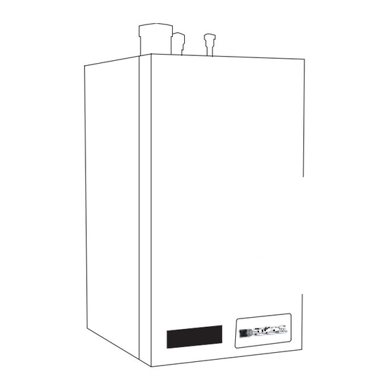
Installing, Operating & Maintaining
EVO 79 - 599 HIGH EFFICIENCY
INNOVA TIVE CONDENSING TECHNOLOGY
By Hamilton Engineering, Inc.
WARNING
injury or death.
New York
MEA 425-05-E
EVO DUO
EVO DUO
300,000 BTU/hr
300,000 BTU/hr
399,000 BTU/hr
630,000 BTU/hr
399,999 BTU/hr
630,000 BTU/hr
Do not store or use gasoline or other
flammable vapors and liquids in the vicinity
of this or any other appliance.
WHAT TO DO IF YOU SMELL GAS:
• Do not try to light any appliance
• Do not touch any electrical switch
• Do not use any phone in your building
Immediately call your gas supplier from a
neighbor's phone. Follow the gas supplier
instructions. If you can not reach your gas
supplier, call the fire department.
Massachusetts
Boilers: G1-06-06-24A
Heaters: G1-06-06-24B
WARNING
INNOVA TIVE CONDENSING TECHNOLOGY
By Hamilton Engineering, Inc.
EVO MICRO
EVO MICRO
80,000 BTU/hr
80,000
BTU/hr
136,000 BTU/hr
136,000 BTU/hr
180,000 BTU/hr
180,000 BTU/hr
199,000 BTU/hr
199,000 BTU/hr
SCAQMD
CEC Listed
Compliant Rule1146.2 California Energy Commission
Advertisement
Table of Contents

Subscribe to Our Youtube Channel
Related Manuals for Evo HW 79

Summary of Contents for Evo HW 79
- Page 1 Installing, Operating & Maintaining EVO 79 - 599 HIGH EFFICIENCY WATER HEATERS AND HEATING BOILERS INNOVA TIVE CONDENSING TECHNOLOGY By Hamilton Engineering, Inc. MICRO INNOVA TIVE CONDENSING TECHNOLOGY By Hamilton Engineering, Inc. EVO MICRO BTU/hr EVO MICRO EVO DUO EVO DUO...
-
Page 2: Using This Manual
USING THIS MANUAL USING THIS MANUAL SPECIAL ATTENTION BOXES DANGER Indicates a condition or hazard which Throughout this manual you will see these special attention boxes similar to this one, WILL cause severe personal injury, which are intended to supplement the death, or major property damage. -
Page 3: Table Of Contents
Internal Wiring Connection SERVICING Part 3 ....10–14 Servicing the EVO Placing EVO into Normal Operation 25 GAS CONNECTION Soft Lockout Codes Gas Connection... -
Page 4: General Information
1. GENERAL INFORMATION A. HOW IT OPERATES The EVO product line is an extremely high efficiency water heating product, requiring special venting and condensate removal precautions. Failure to follow all of the instructions contained in this manual may cause premature product failure that may not be covered under warranty. -
Page 5: Bevo Dimensions
0.75" 1.5" 19" 33" 19" 4" 4" 2.0" 0.75" 1.5" 19" 35" 26.5" 5" 5" 2.0" 1.0" 1.5" (TABLE 1-1) EVO INFORMATION Water Heater* Boiler** GPH* GPH* GPH* Input Shipping Model Output Output Recovery Recovery Recovery Weight BTU/hr BTU/hr BTU/hr @100°F T... -
Page 6: C Pre-Installation Requirements
(see Figure 1-4 on the next page). If the EVO is set up for liquefied petroleum (LP) gas, some geographic areas follow the Uniform Mechanical Code, section 304.6, “Liquefied petroleum gas burning appliances shall not be installed in a pit, basement or similar location where heavier-than-air gas might collect. -
Page 7: D Pressure Relief Valve 7 C
(FIGURE 1-4) HOW TO REMOVE THE FRONT COVER WARNING The EVO is certified as an indoor appliance. Do not install the EVO outdoors or locate where it will be exposed to freezing temperatures. This includes all related piping and components. If the EVO is subjected to flood water or submersed in water, the EVO must be replaced. -
Page 8: Electrical
A. ELECTRICAL CONNECTION The electrical connection for the EVO is on the bottom of the unit. There is a 1/2” knockout location for an electrical connection for the heater’s incoming power connection. All electrical wiring must be performed by a qualified licensed electrician in accordance with National Electrical Code ANSI/NEPA to and/or the Canadian Electrical Code, Part 1 CSA C22.1, or to the applicable codes and standards. - Page 9 External Outside Temperature Cascade Remote 0-10 VDC Power Supply Temperature Pump Lock Out Sensor Additional Connection Thermostat Sensor 60 Hz Signal Heat Source 208 - 240 VAC 208 - 240 VAC Thermistor Dry Contact Dry Contact Thermistor To Pump Fused switch or from a maximum 15 amp dedicated circuit breaker...
-
Page 10: Part 3
EVO from the gas line. In order to do this, you must shut the gas off using factory and field-installed gas cocks (following the lighting instructions in Part 6, Section B, Pages 23-24.) This will prevent high pressure from reaching the valve. -
Page 11: Gas Tables
D. GAS VALVE SETUP increase increase (DO NOT TOUCH!) (FIGURE 3-2) EVO MODELS 79-399 (FIGURE 3-3) EVO MODEL 599 Models 119–399 Model 599 34000 Autry Street, Livonia, MI 48150 • 800.968.5530 • Fax 734.419.0209 • www.hamiltonengineering.com • LIT91127 REV 3/09... - Page 12 GAS CONNECTION Measure the gas supply pressure at the pressure nipple [3] of the gas valve. The required gas supply pressure needed for these appliances to work properly is greater than 4” and less than 14” WC. This pressure range should be maintained during full gas load on the building where the appliance is installed.
-
Page 13: Setting Minimum Load
If the appliance is to be converted in the field for using Propane (LPG), the following steps must be taken: • Turn screw [1] (Figure 3-2, page 11) .75 of a full turn (270°) on models HW 79/199.1,three quarters of one turn (270°) on models HW 199/299 and 1 full turn (360°) on model HW399... -
Page 14: Gas Valve Replacement
Please note: Venting system may contain one or more of the above materials. The EVO is a direct vent appliance. The EVO is listed as a Category IV. Condensing Appliance. (The EVO Venting is rated at Zero Clearance to combustibles.) 34000 Autry Street, Livonia, MI 48150 •... -
Page 15: Venting The Evo
Note: For concrete construction or to meet certain fire codes, exhaust and inlet piping at the wall penetration to the EVO must be CPVC Schedule 40 or 80 or stainless. The balance from the penetrated wall to the outside may be PVC Schedule 40 or 80. - Page 16 VENTING Exhaust piping should be sloped back to the connection on the EVO, at least 1/4” per foot to remove additional condensate that forms within the pipe. The total combined length of pipe (intake piping plus exhaust piping added together) including elbow allowances intake and exhaust should not exceed the length shown in the vent table.
- Page 17 VENTING *IMpORTANT NOTE HAMILTON ENGINEERING, INC. RECOMMENDS A MINIMUM CLEARANCE OF 4 FEET WHERE THE EXHAUST PLUME CAUSED BY THE UNIT MAY OBSTRUCT VIEWS OR AFFECT THE COSMETIC LOOK OF THE BUILDING. IN CANADA, THERE IS A MINIMUM CLEARANCE OF 10 FEET. (FIGURE 4-1) EXIT TERMINALS OF MECHANICAL DRAFT AND DIRECT-VENT VENTING SYSTEM * REFERENCE: THE NATIONAL FUEL GAS CODE 2009 EDITION Through-the-Wall Vent Termination...
- Page 18 VENTING DIAGRAMS FOR SIDEWALL VENTING VENTING MULTIPLE UNITS, with vents all on same horizontal plane, spaced at least PLEASE NOTE: Exhaust must not terminate 8 inches apart, and at level of beneath an overhang! highest unit. 1/4" ft. slope to appliance Exterior wall All horizontal runs must 8"...
-
Page 19: Inlet Air Vent
1. Seal any unused openings in the common venting system. The EVO venting is NOT to be combined with this older venting system! 2. -
Page 20: Condensate Requirements
10 PSI water pressure, this assures that the EVO heat exchanger can be completely purged of air, failure to do so could cause damage. It is important to note that the EVO Boiler is flow dependent for proper efficiency and life expectancy;... -
Page 21: Fill & Purge Heating System
C. REMOVING AIR FROM THE HEAT EXCHANGER The EVO DUO (it is not necessary on an EVO MICRO) has an automatic air vent on the top of the appliance and the air vent cap must be loosened to allow trapped air to escape when the appliance is initially filled and put into operation. -
Page 22: Water Heating Piping
Relief Valve Location Pump Minimum manifold pipe size WATER HEATER Model Design T GPM P Supplied Single Double Triple Quad HW 79 6.6 @ 19.9' 23.5˚F 13.1˚C PMP 30213 1" 1" 1.5" 1.5" 22.2˚C 1" 1.5" 1.5"... -
Page 23: Start Up Procedures
Turn on the power to the EVO. The Setpoint Temperature of the EVO will appear in the display at this time. If a fault code appears, correct the fault before operating. The EVO will now run its pre-purge and ignition cycles, then begin heating, which will be indicated by the green “BURNER ON”... -
Page 24: Operating Instructions
START-UP PROCEDURES The EVO Heater shall be installed so the gas ignition system components are protected from water (dripping, spraying, rain, etc.) during appliance operation and service (circulator replacement, condensate trap, control replacement, etc.). C. OPERATING INSTRUCTIONS STOP! Make sure you have read the safety information above. -
Page 25: Part 7
Undo the two latches at the bottom of the cover (if applicable). Remove the cover. B. PLACING THE EVO INTO NORMAL OPERATION Replace the front cover in the normal position. Close the latches on the bottom of the cabinet (if applicable). -
Page 26: Soft Lockout Codes
SERVICING C. SOFT LOCKOUT CODES (TABLE 7-1) FMT 914 SOFT LOCKOUT CODES DISpLAY WILL AUTOMATICALLY DESCRIpTION CODE RESET whEN: Low water cut off (if equipped) opened The water level is restored Manual reset high limit or low gas pressure switch (if Must reset manually on safety control equipped) opened Outlet temperature too high... - Page 27 SERVICING IN MANY CASES, A “HARD LOCKOUT” WILL INDICATE THAT THERE IS SOMETHING WRONG WITH THE APPLIANCE, THAT SHOULD BE SERVICED OR REPAIRED. EXAMPLE: If there is a loss of flow due to an air bubble passing through the appliance (sensed via the water flow switch), the appliance will shut down and display a temporary fault (H1).
-
Page 28: Fault Causes
SERVICING E. FAULT CAUSES The numbers given in Tables 7-3 and 7-4 match with those in the following table to give the reason for the fault. (TABLE 7-5) FAULT CAUSES Room thermostat Pump not running or partially clogged Water pressure in the system too low (heat exchanger/radiator air bound) Fan speed control wiring not connected (unplugged) Fan blades are fouled - check for lint or dirt build-up on blades Fan is defective... - Page 29 SERVICING (TABLE 7-5) FAULT CAUSES (CONTINUED) Gas valve not correctly adjusted at maximum load Venting system has too much resistance (possibly partially blocked) Setting of the pressure switch is incorrect (setting = 7mbar) Electrical contacts are corroded Wiring to switch is disconnected or incorrectly connected Insufficient flow through the boiler Heat exchanger is beginning to accumulate scale The numbers given in Tables 7-3 and 7-4 match with those in the following table to troubleshoot.
- Page 30 SERVICING (TABLE 7-6) TROUBLESHOOTING THE FAULT (CONTINUED) First check that the pump is circulating like it should, that there are no obstacles between the appliance and the tank (or in any of the inlet/outlet piping), and that the appliance is still making noise.
-
Page 31: To Turn Off Gas To Appliance
650 watts. All standard pumps as supplied by Hamilton Engineering draw 550 watts or less. The EVO control system has the ability to control up to three (3) or two (2) pumps and a diverting valve. For details see EVO Configurations Manual (LIT91110) or contact Hamilton Engineering at 800.968.5530. -
Page 32: Temperature Sensor Reading Instructions
Show Indirect (Tank) Temp. Reset Button Show Cascade Temp. (Direct heated storage tank or common loop sensor) Reset Button Show Outside Temp. Reset Button Normal Display I. EVO SENSOR RESISTANCE TABLE (TABLE 7-7) EVO SENSOR TEMpERATURE RESISTANCE TEMpERATURE RESISTANCE RESISTANCE TABLE (OhM) (OhM) -
Page 33: Part 8
8. MAINTENANCE A. MAINTENANCE PROCEDURES Once a year, a qualified service technician should perform maintenance on your EVO equipment to ensure that everything is operating safely and efficiently. The owner can make necessary arrangements with a qualified heating contractor for proper maintenance of the heater. The equipment installer must also inform the owner that the lack of proper care and maintenance of the heater may result in a hazardous condition. -
Page 34: Condensate Cleaning Instructions
(try to avoid getting the back ceramic (target) wall of the unit wet). Flush the combustion chamber with fresh water. At this point, the EVO should be ready to power back up. Before powering up the EVO follow the steps below Re-install the burner assembly and rear target wall (ceramic insulation) Replace the (6) 6mm nuts to the burner plate. -
Page 35: Evo Controls
MAINTENANCE Turn the EVO back on** and monitor the condensate drain until flow has been established. Re-connect the condensate hose to the outside connection. **NOTE: when firing up the boiler for the first few times you may experience some fluttering of the gas burner that may result in a flame lockout. -
Page 36: Installation At High Altitudes
G. COIL ANTI-SCALING PREVENTION FEATURE The EVO controller (FMT 914) contains sophisticated software that enables it to monitor the rate of temperature rise through the heat exchanger. By doing this, it greatly reduces the possibility of heat exchanger failure due to scaling or fouling. -
Page 37: Water Heater Operating Sample
MAINTENANCE H. WATER HEATER OPERATING SAMPLE All of the following parameters are controlled by either a storage tank temperature sensor or the inlet tempera- ture sensor: • Setpoint = Target Temperature (120°F) Low fire only above this point • Offset = Off Setpoint (3) = 123°F off •... -
Page 38: Evo Micro Parts Breakdown
MAINTENANCE I. EVO MICRO (HW 79-199.1 & 199.8) PARTS BREAKDOWN NUMBER ON DRAWING pART DESCRIpTION pART NUMBER Front panel JKR 74076 Pressure Switch PRS 74326 Flue gas collector MSC 74112 Seal ring 60mm GKT 74022 Seal ring flue gas collector-heat exchanger... - Page 39 MAINTENANCE I. EVO MICRO (HW 79-199.1 & 199.8) PARTS BREAKDOWN (CONTINUED) NUMBER ON DRAWING pART DESCRIpTION pART NUMBER Nut with flange 6ea. (M6 x 0.1) MSC 74012 22,24 Electrode Assembly PLT 74058 Flow Switch Ignition cable with plug WRE 74064 Burner Gasket burner &...
-
Page 40: Evo Duo Parts Breakdown
MAINTENANCE J. EVO DUO (HW 299-599) PARTS BREAKDOWN 299-399 NO. ON pART DESCRIpTION pART NO. pART NO. pART NO. DRAWING Side panel JKR 74071 JKR 74071 JKR 74072 Front panel JKR 74073 JKR 74073 JKR 74074 3, 53, 56 Seal ring 115mm / 130mm... - Page 41 MAINTENANCE J. EVO DUO (HW 299-599) PARTS BREAKDOWN (CONTINUED) NO. ON pART DESCRIpTION pART NO. pART NO. pART NO. DRAWING Flow Switch Air / gas mixing pipe - fan to burner BNR 74018 BNR 74018 BNR 74016 Gasket air / gas inlet pipe & fan...
-
Page 42: Wiring Diagrams
Customer: ENGINEERING PH: (800) 968-5530 Description: Fax: (734) 419-0209 EVO duo (HWH 199-599 w/o 3-way) Dwg. Wiring Diagram with Heating Options No.: Checked. 34000 Autry Street, Livonia, MI 48150 • 800.968.5530 • Fax 734.419.0209 • www.hamiltonengineering.com • LIT91127 REV 3/09... - Page 43 Livonia, MI 48150 Customer: ENGINEERING PH: (800) 968-5530 Description: Fax: (734) 419-0209 EVO duo (HWH 199-599 w/3-way) Dwg. Wiring Diagram with Heating Options No.: Checked. 34000 Autry Street, Livonia, MI 48150 • 800.968.5530 • Fax 734.419.0209 • www.hamiltonengineering.com • LIT91127 REV 3/09...
- Page 44 HWH 79-199.1 HEATER BOILER WIRING DIAGRAM WITH 3 PUMPS 34000 Autry Street, Livonia, MI 48150 • 800.968.5530 • Fax 734.419.0209 • www.hamiltonengineering.com • LIT91127 REV 3/09 Page 44 of 50...
- Page 45 HWH 79-199.1 HEATER BOILER WIRING DIAGRAM WITH DIVERTING VALVE 34000 Autry Street, Livonia, MI 48150 • 800.968.5530 • Fax 734.419.0209 • www.hamiltonengineering.com • LIT91127 REV 3/09 Page 45 of 50...
- Page 46 Livonia, MI 48150 Customer: ENGINEERING PH: (800) 968-5530 Description: Fax: (734) 419-0209 EVO duo (HWD 199-599) Dwg. Wiring Diagram for Water Heaters No.: Checked. 34000 Autry Street, Livonia, MI 48150 • 800.968.5530 • Fax 734.419.0209 • www.hamiltonengineering.com • LIT91127 REV 3/09...
- Page 47 STANDARD INTERNAL WIRING DIAGRAM MODELS HWD 79-199.1 34000 Autry Street, Livonia, MI 48150 • 800.968.5530 • Fax 734.419.0209 • www.hamiltonengineering.com • LIT91127 REV 3/09 Page 47 of 50...
-
Page 48: Installation Requirements (Massachusetts)
INSTALLATION REQUIREMENTS Requirements for installation – Commonwealth of Massachusetts For all side wall horizontally vented gas fueled equipment installed in every dwelling, building or structure used in whole or in part for residential purposes, including those owned or operated by the Commonwealth and where the side wall exhaust vent termination is less than seven (7) feet above finished grade in the area of the venting, including but not limited to decks and porches, the following requirements shall be satisfied: 1. - Page 49 NOTES 34000 Autry Street, Livonia, MI 48150 • 800.968.5530 • Fax 734.419.0209 • www.hamiltonengineering.com • LIT91127 REV 3/09 Page 49 of 50...
- Page 50 NOTES 34000 Autry Street, Livonia, MI 48150 • 800.968.5530 • Fax 734.419.0209 • www.hamiltonengineering.com • LIT91127 REV 3/09 Page 50 of 50...
Need help?
Do you have a question about the HW 79 and is the answer not in the manual?
Questions and answers