
Related Manuals for Universal MRF-350


Summary of Contents for Universal MRF-350
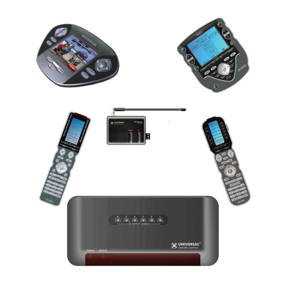
- Page 1 MRF-350 Installation Manual Optimizing Narrow Band Reception with the RFX-250 and MSC System Remotes...
- Page 2 MRF-350 Installation Manual ©2006 - 2013 Universal Remote Control, Inc. The information in this owner’s manual is copyright protected. No part of this manual may be copied or reproduced in any form without prior written consent from Universal Remote Control, Inc.
-
Page 3: Table Of Contents
able OnTenTs Introduction Features and Benefits Parts Guide Optimizing Range and Reliability Connecting IR and Setting Output Levels Front Blaster Overload Disabling the Front Blaster - Step by Step via PC Controlling An Array of Identical Components or Zones Identical Components/Zone - Step by Step via PC Programming For Multiple Equipment Locations Frequently Asked Questions Warranty... -
Page 4: Introduction
TaTiOn Introduction The MRF-350 base station is an “addressable” base station like the MRF-300. RF Addressing gives you the ability to control as many as 90 identical compo- nents throughout a house. However, the MRF-350 is equipped with the Narrow Band RF reception, so is only compatible with MSC System remotes. -
Page 5: Features And Benefits
Each MRF-350 has six “addressable” IR Line Outputs. For example, you can con- trol up to six identical TV’ s with one MRF-350 or route volume commands for a specific zone to a particular zone IR input on a multi-zone preamp. If you have... -
Page 6: Optimizing Range And Reliability
RF Interference (particularly devices with high speed microprocessors or hard drives). 2. Check that the address wheel on the bottom of the MRF-350 is set to ID#0 (the interference “sniffing” position). Slide off the mounting plate to reveal the RF ID# rotary switch. Check that the arrow pointer in the center of the wheel is pointed to 0, the default “interence sniffing”... - Page 7 MOVE the RFX-250 to a new location. 6. Observe the STATUS LED of the MRF-350. It is a little more sensitive than the RFX-250. If you see any flickering of this LED, move the RFX- 250 to a new location.
- Page 8 VALID RF ID#. Keep in mind that zero (0) is not a valid RF ID#. Watch the STATUS LED on MRF-350 - it should light every time you press a button on the remote. This will tell you that the signal was received and understood.
-
Page 9: Connecting Ir And Setting Output Levels
Input, cut the flasher off of the wire, strip the conductor is IR two conductors and connect to the rear panel IR DATA (Tip of the Input. The MRF-350 is only compatible with Plug). standard IR Inputs, not proprietary control sys- tems offered by some manufacturers. -
Page 10: Front Blaster Overload
Disable the Front Blaster. This will limit the number of components your MRF-350 can control to six. If you have more than six components you can purchase an additional MRF-350. -
Page 11: Controlling An Array Of Identical Components Or Zones
There are several considerations to take into account when you are installing an MRF-350 to control an array of identical components: 1. The RF ID# cannot be set to Code 0, the universal setting. You must use one of the fifteen unique IR Routing addresses. - Page 12 MRf-350 b TaTiOn step 3 - Copy The Programmed Device In tree view, right click on the device you programmed. From the context menu that appears, select COPY. step 4 - Paste The Programmed Device In tree view, right click on the first device that is NOT PROGRAMMED.
- Page 13 MRf-350 b TaTiOn Click on the “cell” for the first Signal Column identical TV, by crossing the device row with the Signals col- umn. TV1 Device Row select Rf from the three options shown for eaCh of the identical TVs. You may leave the other components of the system set to iR &...
-
Page 14: Programming For Multiple Equipment Locations
Rename button. Each LOCATION should have a unique ID#. It is ok to install multiple MRF-350’s in one location. step 4 - save and Download to your remote. Page 11... -
Page 15: Frequently Asked Questions
350, second, check that the flasher level is set to the minimum necessary, third, check that the emitter is facing the component, fourth, make sure the RFX-250 is correctly connected to the MRF-350 RF Inputs (Step 4, Page 3) Page 12... -
Page 16: Warranty
MRf-350 b TaTiOn 1. LIMITED WARRANTY AND DISCLAIMERS Universal Remote Control, Inc. (“URC”) warrants that URC equipment purchased directly from URC or from an authorized URC dealer or distributor shall be free from defects in material and workmanship under normal usage for a period of one (1) year from... - Page 17 MRf-350 b TaTiOn EXPRESSLY DISCLAIMS ALL WARRANTIES RELATING TO TECHNICAL SERVICES, EXPRESS, STATUTORY OR IMPLIED, INCLUDING BUT NOT LIMITED TO THE WARRANTIES OF QUALITY OR REASONABLE SKILL AND CARE, OR OUTCOME OR RESULTS. WITHOUT IN ANY WAY LIMITING THE GENERALITY OF THE...
-
Page 18: End User Agreement
MRf-350 b TaTiOn equipment is not eligible for URC tech support or software support, either. 2. URC'S LIMITATIONS OF LIABILITY IN NO EVENT SHALL URC BE LIABLE FOR INDIRECT, SPECIAL, INCIDENTAL, EXEMPLARY, PUNITIVE OR CONSEQUENTIAL DAMAGES OF ANY KIND OR LOSS OF PROFITS OR BUSINESS OPPORTUNITY, EVEN IF URC IS ADVISED OF THE POSSIBILITY OF SUCH DAMAGES. -
Page 19: Information To The User
Information To The User This equipment has been tested and found to comply with the lim- its for a Class B digital device, pursuant to part 15 of the FCC Rules. These limits are designed to provide reasonable protection against harmful interference in a residential installation. This equip- ment generates, uses and can radiate radio frequency energy and, if not installed and used in accordance with the instructions, may cause harmful interference to radio communications.
Need help?
Do you have a question about the MRF-350 and is the answer not in the manual?
Questions and answers