
Related Manuals for Samsung CE2974R


Summary of Contents for Samsung CE2974R
-
Page 1: Table Of Contents
MICROWAVE OVEN CE2974R (WHITE) SERVICE Manual MICROWAVE OVEN CONTENTS 1. Precaution 2. Specifications 3. Operating Instructions 4. Disassembly and Reassembly 5. Alignment and Adjustments 6. Troubleshooting 7. Exploded Views and Parts List 8. PCB Diagrams 9. Schematic Diagrams SRSC... - Page 2 (e) A Microwave leakage check to verify compliance with the Federal performance standard should be performed on each oven prior to release to the owner. Samsung Electronics...
-
Page 3: Precaution
10. Service technicians should remove their 16. Always connect a test instrument's ground watches while repairing an MWO. lead to the instrument chassis ground before connecting the positive lead; always remove the instrument's ground lead last. Samsung Electronics... - Page 4 PRECAUTION with the oven energized. Servicemen should remove their watches whenever DO NOT measure the voltage in the high voltage circuit working close to or replacing the magnetron. including filament voltage of magnetron. Samsung Electronics...
-
Page 5: Specifications
(IEC-705 TEST PROCEDURE) OPERATING FREQUENCY 2,450MHz MAGNETRON OM75PH(31) COOLING METHOD COOLING FAN MOTOR OUTSIDE DIMENSIONS 517(W) x 297(H) x 424(D) 2-2 Comparison Chart AUTO REHEAT AUTO COOK POWER LEVEL TIME SETTING AND WEIGHT AUTO DEFROST GRILL COOK COMBI COOK Samsung Electronics... -
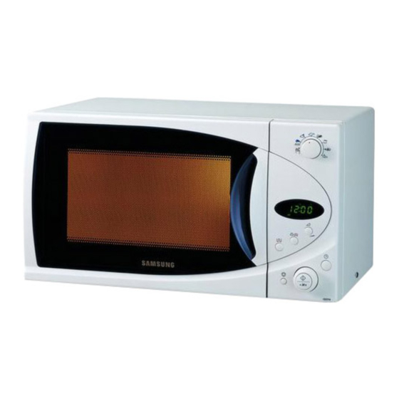
Page 6: Operating Instructions
Stop/Cancel Button Start Button/Dial Knob (cook time, weight and serving dishes) 3-2 Features & External Views Door Grill Safety Interlock Holes Light Ventilation Holes Door Handle Display Control Panel Glass Plate Roller Ring Door Latches Coupler 517mm 424mm Samsung Electronics... -
Page 7: Disassembly And Reassembly
HIGH VOLTAGE TRANSFORMER secondary and filament terminals. It is extremely dangerous to work on or near these circuits with the oven energized. DO NOT measure the voltage in the high voltage circuit including filament voltage of magnetron. Samsung Electronics... -
Page 8: Replacement Of Door Assembly
1. Insertion depth of the thin metal plate should be 0.5mm or less. 4-3-4 Removal of Key Door & Spring Remove pin hinge from Door "E" Detach spring from Door "E" and key door. Door "E" Key Door Spring Samsung Electronics... -
Page 9: Replacement Of Fuse/Drive Motor
Base Plate Drive Motor Cover 8. Connect all the leads to the drive motor. 9. Screw the deive motor cover to the base plate with a screw driver. 10. Remount the coupler in the correct position. Samsung Electronics... - Page 10 3. Lift up the control circuit board from the Ass'y Connector control box. 4. When reconnecting the FPC connector, make sure that the holes on the connector are properly screw engaged with the hooks on the Plastic Fastener. Samsung Electronics...
-
Page 11: Alignment And Adjustments
2. Isolate the magnetron from the circuit by disconnecting its leads. 3. A continuity check across the magnetron filament terminals should indicate one ohm or less. 4. A continuity check between each filament terminal and magnetron case should read open. Cooling Fins Samsung Electronics... -
Page 12: High Voltage Capacitor
¥ Primary switch 5. Confirm that the gap between the switch ¥ Monitor switch (COM-NC) housing and the switch actuator is no more than ¥ Monitor switch (COM-NO) 0.5mm when door is closed. ¥ Door Sensing S/W Samsung Electronics... - Page 13 NOTE 1: Variations or errors in the test procedure will cause a variance in the temperature rise. Additional power test should be made if temperature rise is marginal. NOTE 2: Output power in watts is computed by multiplying the temperature rise (step E) by a factor of 91 times the of centigrade temperature. Samsung Electronics...
-
Page 14: Procedure For Measurement Of Microwave Energy Leakage
; CENTRAL SERVICE CENTER 5-12-2 At least once a year have the microwave energy survey meter checked for accuracy by its manufacturer. Samsung Electronics... -
Page 15: Troubleshooting
H.V.Transformer component test procedure and replace if it is H.V.Capacitor defective. H.V.Diode, H.V.Fuse Magnetron 4. Open or loose wiring of power relay 5. Defective primary latch switch 6. Defective power relay or Ass'y PCB Replace PCB main. Samsung Electronics... - Page 16 Use plastic wrap or cover with a lid. Stir once or twice while cooking foods such as soup, cocoa, or milk. Noise from the turntable motor Noise may result from the motor. Replace turntable motor. when it starts to operate. Samsung Electronics...
-
Page 17: Exploded Views And Parts List
7. Exploded Views and Parts List 7-1 Exploded Views M14 M16 Samsung Electronics... -
Page 18: Main Parts List
DE61-30006A SUPPORTER-HEATER ALUMINA,5G,2ND-W/P DE61-70060A SPRING-PLATE SK-5,T0.5 DE47-00002A THERMOSTAT PW2N,-,-,100,110 GRILL-TCO DE62-20064A DUCT-AIR SECC1-P,T0.5 DE94-00176N ASSY DOOR CE2914R/BWT,RUSSIA/WHITE,FISH2 DE94-00138M ASSY CONTROL-BOX 230V50HZ,CE2974R/BWT,WHITE,FISH2,RUSSIA DE74-20015B TRAY-COOKING GLASS,T6.0,PI318,1050G,MW5630T DE92-90189U ASSY-GUIDE ROLLER 1.0CUFT(PPS)15.5 DE67-60081A COUPLER PPS,-,-,-,3RD-1.0/1.3 DE74-70081A RACK-WIRE HSWR,PI3,W268,H110,-,MW5584W DE27-10020C COIL-CHOKE TC-104,0.9UH*2,-,L31*W20*H32,-,ABS,AC250V/14 DE39-40409A WIRE HARNESS-E... -
Page 19: Door Parts List
HINGE-LOWER SCP1,T2.3,26,77,ZPC3,WHT,CE945 DE94-00173P ASSY DOOR-A CE2914R/BWT,WHITE/RUSSIA,FISH2 7-4 Control Parts List Ref. No. Parts No. Description Specification Q'ty Remarks DE67-40145A WINDOW-DISPLAY ACRYL,T2,W40,L77,SMOG,30G DE71-00031V COVER-PANEL ABS,CE2974R/BWT,-,-,WHITE,3RD-1.0,FISH2 DE72-00006V CONTROL-PANEL ABS,CE2974R/BWT,-,-,-,-,WHITE,RUSSIA DE66-20176E BUTTON-SELECT-C ABS(HR0370U),5G,-,WHT,M959 DE66-20175E BUTTON-SELECT-B ABS(HR0370U),5G,-,WHT,M959 DE66-00007A BUTTON-TRAY ABS,-,-,WHT,10G DE66-00010A BUTTON-CANCEL ABS,-,D16.3,WHT,5G DE66-20182J... -
Page 20: Standard Parts List
DE60-10098A SCREW-ASSY TAP TITE PH,TC,M4X8,SWRCH18A,ZPC2,GLD,W M/DRIV DE60-10122A SCREW-TAP TH TAP,TH,2-4X8,FE,FN C-CEIL DE60-20063A BOLT-FLANGE M4,10,ZPC3,YEL,MSWR HI-LOW DE60-20063A BOLT-FLANGE M4,10,ZPC3,YEL,MSWR HI-UPP DE60-10045A SCREW-TAP PH PH,M3,L6,FEFZY DE60-10088A SCREW-TAP PH PH,M3,L8,FEFZY,PLAIN DE60-10069A SCREW-TAP TH TH,M4,L10,FRFZY DE60-10082J SCREW-TAPPING TH,2S-4X8,MSWR3,ZPC,YEL,WS DE60-10012A SCREW-TAP TITE TH,+,3,M4,L10,SWR10,ZPC2,TOOTH Samsung Electronics... - Page 21 8. P.C.B Diagrams 8-1 P.C.B Diagrams Samsung Electronics...
- Page 22 3501-001068 RELAY-POWER 24Vdc,523mW,16A,1FormA,15mS,10 RY05 3501-001155 RELAY-MINIATURE 24VDC,200MW,3000MA,1FORMA,10MS,10MS RY02,RY04 3601-001126 FUSE-FERRULE 250V,1.6A,FA,CERAMIC,5X20MM FUSE 3708-001315 CONNECTOR-FPC/FC/PIC 12P,2mm,STRAIGHT,SN CN04 DE09-00049A IC-MCU HD404316-E02S,CE2974R/CE2774R,4BIP,SDIP IC01 DE26-20146A TRANS-L.V SLV-745EN,230V,50HZ,AC17/7V LVT1 DE30-20016A BUZZER CBE2220BA,STICK BUZ1 DE34-20071A SWITCH-ROTARY DC10V,1MA,SH,PA-1005A-003-000 ECD1 DE39-40723A WIRE HARNESS DC35V,C-959G,80mm,12PIN CN05 DE47-40024A HOLDER-FUSE FH-51H,7.5A...
-
Page 23: Schematic Diagrams
POWER MUST BE DISCONNECTED THERMOPLASTIC COVERED WIRE EXCEPT BEFORE SERVICING THIS APPLIANCE FOR HIGH VOLTAGE LEADS OR AS NOTED ON SPECIAL LEADS. MAGNETRON HIGH VOLTAGE DIODE TO CHASSIS HIGH VOLTAGE CAPACITOR SYMBOL COLOR ORANGE HIGH VOLTAGE BLACK TRANSFORMER Samsung Electronics...
Need help?
Do you have a question about the CE2974R and is the answer not in the manual?
Questions and answers