
Subscribe to Our Youtube Channel
Summary of Contents for Midland FLM60H
- Page 1 MIDLAND POWER DISTRIBUTION LIMITED qualit y servi ce support FLM60H User Manual www.midlandpower.co.uk...
-
Page 2: Table Of Contents
- FLAIL MOWER MANUAL - CONTENTS USE OF THE MANUAL................pag. 4 NOTICE ON THE MACHINE..............pag. 5 TECHNICAL DATA...................pag. 8 LIFTING AND TRANSPORTATION............pag. 9 MAIN PARTS OF THE MACHINE............pag. 10 CONTROLS AND ADJUSTMENTS............pag. 12 ASSEMBLY INSTRUCTIONS FOR THE HANDLEBARS AND FRONT SUPPORT WITH WHEELS............pag. 14 SAFETY INFORMATION A) GENERAL INSTRUCITONS..............pag. -
Page 3: Use Of The Manual
Operating and Safety Instruction FLAIL MOWER MOD. 610 FOREWORD This machine may only be utilized for the purpose for which it was designed, i.e. agricultural use, for the cutting of shoots, grass and brushwood. Any other use other than that stated, not covered or deducible from this Manual and the enclosed Engine Manual is "PROHIBITED". -
Page 4: Notice On The Machine
NOTICE ON THE MACHINE The symbols affixed to the machine serving to warn of danger during its use and maintenance are as follows: THE USER MUST READ THE INSTRUCTION MANUAL PROVIDED DANGER OF FOREIGN OBJECTS BEING THROWN OUTWARDS. KEEP A SAFE DISTANCE ALWAYS DISCONNECT THE CABLE FROM THE ENGINE SPARK PLUG. - Page 5 DANGER OF CRUSHING. KEEP A SAFE DISTANCE DANGER OF INJURY TO BOTH UPPER AND LOWER LIMBS. DO NOT PUT HANDS OR FEET INSIDE THE CUTTING ELEMENT WHILE IN MOTION DANGER OF GETTING CAUGHT UP IN ROTATING PARTS. DO NOT PUT HANDS IN THE ROTATING PARTS DANGER OF FOREIGN OBJECTS BEING THROWN OUTWARDS.
- Page 6 EAR DO NOT ALLOW CHILDREN NEAR THE MACHINE WHEN IN OPERATION.MUFFS MUST BE WORN CAUTION: HOT PARTS. DANGER OF BURNS. FIRE HAZARD The symbols affixed to the machine serve to warn of danger during its use and maintenance. It is vitally important to understand the meaning of the danger notices and all messages should be kept in legible condition.
-
Page 7: Technical Data
TECHNICAL DATA OF THE MODEL 610 ENGINE: petrol HONDA GX 200 K1 ENGINE CAPACITY: 4.8 kW (6.5 HP) ENGINE FILTER: dry filter WORKING WIDTH: 60 cm CUTTING HEIGHT: adjustable 20 - 80 mm CUTTING SYSTEM: 32 flail rotor SPEED GEARS: 2 forward gears –... -
Page 8: Lifting And Transportation
LTITUDE The altitude of the place in which the machine is to be used must not exceed 1500 m above sea level. EMPERATURE Minimum ambient temperature: -5°C Maximum ambient temperature: +50°C TMOSPHERIC ONDITIONS The electrical equipment will function correctly in atmospheric conditions with a relative humidity up to 50% at a temperature of 40°C and at 90% with a temperature up to 20°C (without condensate). -
Page 9: Main Parts Of The Machine
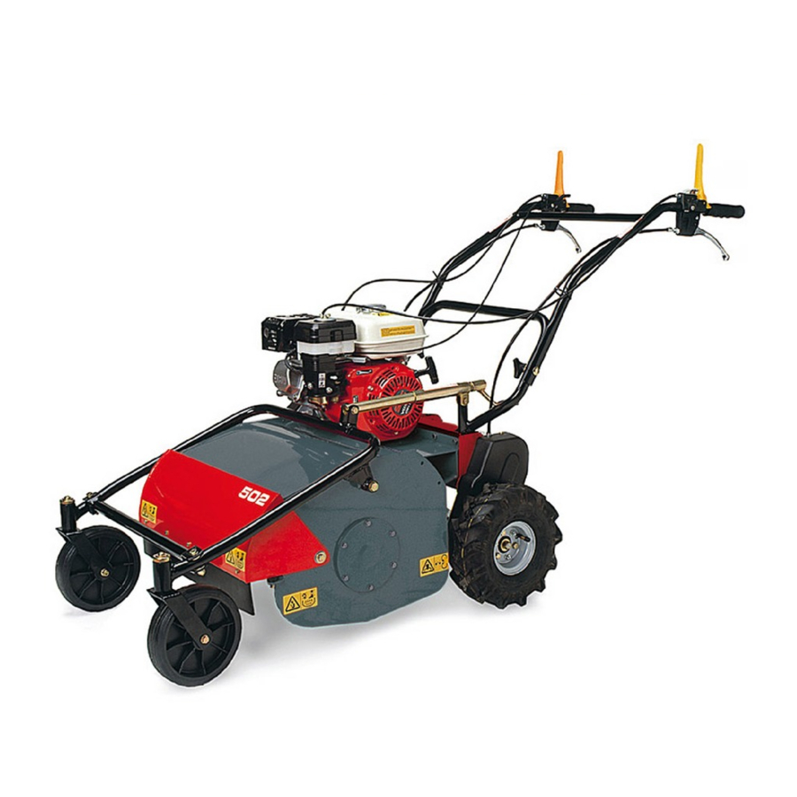
5. MAIN PARTS OF THE MACHINE The machine consists of the following main parts: FORWARD CLUTCH CONTROL LEVER ACCELERATOR CONTROL LEVER FLAIL ROTOR CLUTCH CONTROL LEVER RIGHT WHEEL RELEASE LEVER E1 - LEFT WHEEL RELEASE LEVER ENGINE FRONT WHEELS FRONT GUARD CUTTING HEIGHT ADJUSTMENT LEVER HANDLEBAR HEIGHT ADJUSTMENT LEVER ON/OFF SWITCH (1/0) - Page 10 Figure 1 Figure 2 - 11 -...
-
Page 11: Controls And Adjustments
6. CONTROLS AND ADJUSTMENTS A) FORWARD CLUTCH CONTROL LEVER This lever only has two positions: engage and disengage. Lowering the lever engages the clutch and releasing it disengages the clutch. The service brake is connected to this lever. The brake operates automatically when the clutch is disengaged. B) ACCELERATOR CONTROL LEVER This is used to adjust the number of engine revolutions according to the operations to be carried out. - Page 12 I) CUTTING HEIGHT ADJUSTMENT LEVER This lever serves to adjust the cutting height. Warning: if the cutting height is set too low the following undesirable consequences may occur: foreign objects such as stones, etc., may be thrown outwards dirt and mud may accumulate inside the rotor guard, thus impeding regular discharge of cut grass.
-
Page 13: Assembly Instructions For The Handlebars And Front Support With Wheels
7. ASSEMBLY INSTRUCTIONS FOR THE HANDLEBARS AND FRONT SUPPORT WITH WHEELS The flail mower is delivered with the handlebars and front support with wheels disassembled. Remove the cardboard packaging or crate (to be disposed of in an appropriate manner, in accordance with current regulations in force). To assemble, proceed as follows : Lift the handlebar and insert it in the support shown in Fig. -
Page 14: Safety Information
8. SAFETY INFORMATION Before using the flail mower it is essential that the operator has understood the warnings, do’s and don’ts and precautionary measures given in this manual and in the engine manual: the prevention of injury to the operator, third parties, animals or objects directly depends on observance of these instructions. -
Page 15: D) Working Use
Do not switch on and operate the flail mower in enclosed areas since the engine gives off carbon monoxide fumes which are colourless, odourless, tasteless and extremely dangerous. Take care when handling fuel. Fuel is highly flammable and its vapours explosive : - Only use an approved container. -
Page 16: E) After Work
When working in a stony or obstacle-riddled area try to remove as many objects as possible before commencing cutting. Then work at a greater cutting height than usual. WARNING Stones and other objects may be thrown outwards in direction of the operator or of other persons in the vicinity. -
Page 17: Transportation Of The Machine
9. TRANSPORTATION OF THE MACHINE LOADING AND UNLOADING FROM A VEHICLE For transportation it is pReferable to use a vehicle with an open bed. Choose firm, flat ground. Switch off the vehicle’s ignition, put into reverse gear, pull on the hand brake and block the tyres with chocks to prevent accidental movement of the vehicle. -
Page 18: Safety Systems And Guards
10. SAFETY AND GUARD SYSTEMS WARNING The safety devices must never be tampered with. It is necessary to understand how they work and safeguard their efficiency and correct operation. In the instance of doubt, prob- lems or malfunction contact your dealer. FORWARD CONTROL AND FLAIL MOVEMENT LEVERS When released both of these levers instantly disengage the transmission connected to them, thus automatically engaging their respective brakes, hence the machine service... -
Page 19: Starting And Driving The Flail Mower
12. STARTING AND DRIVING THE FLAIL MOWER The machine can be switched on once all the aforementioned preliminary operations have been carried out. Place the feed cock in the OPEN position (direction shown by the arrow, Fig. 4). Bring the choke to the CLOSED position for a cold start (direction shown by the arrow, Fig. - Page 20 DRIVING THE MACHINE WARNING When using the machine for the first time it is advisable to get the feel of it by executing manoeuvres on flat ground free of foreign objects. Cut in a straight line at low speed, slightly overlapping the section cut previously. After switching on the engine following the instructions given in the previous paragraph: 1.
-
Page 21: Cutting Tips
13. CUTTING TIPS 1. Before commencing cutting operations, read the safety instructions given in the previous sections. 2. Before engaging flail movement using the relative lever ( Figure 1 Ref. D) the guard (Fig. 1 Ref. H) must be fully lowered to prevent the outward projection of objects. 3. -
Page 22: B) Cable Control Adjustment
B) CABLE CONTROL ADJUSTMENT To adjust the cables place the machine on flat ground, switch off the engine and disconnect the wire from the spark plug. Figure 5 B1) RIGHT AND LEFT WHEEL RELEASE CABLES ( Fig. 5 Ref. A) Inspect or move the cable sheathing slightly to ensure play of 1-2 mm between the upper part of the cable and the adjustment screw (Fig. - Page 23 B2. BLADE ROTOR CONTROL CABLE BLADE ROTOR BRAKE CONTROL CABLE The two cables are controlled at the same time by the lever located on the handlebar in fig. 5 Rif. B. When the lever is operated the two cables engage simultaneously: the blade rotor moves, its brake becoming disengaged.
-
Page 24: C) Brakes Adjustment
C) BRAKE ADJUSTMENT To adjust the brake cables place the machine on a flat surface, switch off the engine and disconnect the spark plug wire. C1) ROTOR BRAKE Loosen and remove the screw (Fig. 7 Ref. B). Remove the brake adjustment device (Fig. 7 Ref. A ). Shorten or lengthen the threaded pin as necessary (Fig. -
Page 25: D) Belt Replacement And Adjustment
D) BELT REPLACEMENT AND ADJUSTMENT If a belt breaks or becomes worn it is advisable to change both belts connected to the engine at the same time. The replacement of just one belt alone may give rise to adjustment problems. Conversely, the blade rotor control belt is completely independent of the others, so for its replacement or adjustment carry out the following: D1) BLADE ROTOR DRIVE BELT... - Page 26 D2) FORWARD BELT Remove the brake adjustment device (Fig.7 Ref. A) by unscrewing the screw (Fig. 7 Ref. B) and slipping off the rotor engagement belt (Fig.12 Ref. A) turning the engine pulley anticlockwise. Slip off the transmission belt (Fig. 11 Ref. A) from the large pulley side (Fig. 11 Ref. B) and turning the engine pulley anticlockwise (Fig.
- Page 27 D3) ROTOR ENGAGEMENT BELT The rotor engagement belt should only be replaced and adjusted after having first replaced the forward belt( point D2) Remove the belt (Fig. 12 Ref. A) turning the engine pulley (Fig. 12 Ref. C) anticlockwise. Fit the new belt by slipping it onto the large pulley (Fig.
-
Page 28: E) Checking And Replacing The Flails
E) CHECKING AND REPLACING THE FLAILS Always check the state of the flails before commencing work. Do not forget to switch the engine off! Checking and replacement of the flails requires the assistance of another person to hold the handlebars down to tilt up the front part of the machine. The flails will be presented as shown in Figure 15. -
Page 29: F) Sharpening The Flails
To remove the flails proceed as follows: 1. Switch off the engine and disconnect the spark plug wire 2. Adjust the cutting height to maximum 3. Open the front housing. 4. Check the state of the flails. 5. Check that the flails are not cracked, bent, excessively worn or broken. If they are, either reverse them (turning them 180°) or replace them. -
Page 30: G) Checking And Replacing The Transmission Oil
G) CHECKING AND REPLACING THE TRANSMISSION OIL Check the transmission oil level using the relative level cap (Fig. 16 Ref. A). If oil leaks out upon removal of this cap then there is enough of it in the transmission. If not, remove the filling cap shown in Fig. -
Page 31: Maintenance And Storage
15. MAINTENANCE AND STORAGE All operations on the machine must be carried out exclusively by authorized personnel. Always switch off the engine when checking, adjusting or servicing the machine. Allow the machine to cool down before inspection. The belt guard (Fig. 9 Ref.s. D and C) and flail guards ( Fig. 1 Ref. H) must always be correctly installed and intact. -
Page 32: Cleaning The Machine
After use store the machine in a place where children have no access. Always allow the machine to cool down before putting it away. After use store the machine in a place where fuel vapours cannot reach a naked flame or sparks. -
Page 33: Decommissioning And Scrapping
18. DECOMMISSIONING AND SCRAPPING After the working life of the flail mower the user must have it dismantled and its components removed as per EEC directives or in accordance with current legislation in force in his country, taking particular care over the dismantling of the following materials of environmental impact: plastic parts rubber parts... -
Page 34: Ce Marking
21. CE MARKING The plate bearing the CE mark gives the main characteristics and information for the identification of the flail mower. Manufacturer’s details Machine model Serial number Year of construction Capacity in kW Weight in kg The above information must not be altered or modified in any way. It is up to the user to keep the plate clean, legible and in good condition. -
Page 35: Troubleshooting
22. TROUBLESHOOTING The following table illustrates some problems which may arise during operation. FAULT CAUSE MEASURES TO BE TAKEN Grass ejection insufficient 1. Grass wet 1. Wait until the grass has dried 2. Grass too long 2. Go over the grass twice, changing the cutting height 3. - Page 36 ENGINE FAULT CAUSE MEASURES TO BE TAKEN Engine sluggish at switch on accelerator not in start-up 1. move the accelerator to the position intermediate position Choke not closed 2. Close the choke when cold. Petrol does not arrive 3. Check the fuel tank and remove water sediment.
- Page 37 NOTES _________________________________________________________________ _________________________________________________________________ _________________________________________________________________ _________________________________________________________________ _________________________________________________________________ _________________________________________________________________ _________________________________________________________________ _________________________________________________________________ _________________________________________________________________ _________________________________________________________________ _________________________________________________________________ _________________________________________________________________ _________________________________________________________________ _________________________________________________________________ _________________________________________________________________ _________________________________________________________________ _________________________________________________________________ _________________________________________________________________ _________________________________________________________________ _________________________________________________________________ _________________________________________________________________ _________________________________________________________________ _________________________________________________________________ _________________________________________________________________ _________________________________________________________________ _________________________________________________________________ _________________________________________________________________ - 38 -...
-
Page 38: Ce Declaration Of Conformity
CE DECLARATION OF CONFORMITY The undersigned GALGI Srl Via Andrea Costa, 4 44042 Cento (FE) - Italy declares under its own responsibility that the new machine type: FLAIL MOWER model: serial number : from H000... to H000..year of construction: 2008 described as follows: Machine for agricultural use for the cutting of shoots, grass and brushwood...
Need help?
Do you have a question about the FLM60H and is the answer not in the manual?
Questions and answers
FLM60H parts list, part number for belts