Table of Contents
Advertisement
Advertisement
Table of Contents

Related Manuals for Winland EnviroAlert EA200


Summary of Contents for Winland EnviroAlert EA200
- Page 2 Limitations of the Alarm System or Device While your alarm system or device is reliable and sophisticated, it does not offer guaranteed protection against burglary, fire, or other emergency. Any security product, whether commercial or residential, is subject to compromise or failure-to-warn for a variety of reasons. These include: •...
-
Page 3: Table Of Contents
EnviroAlert EA200........ - Page 4 Using the EA200 / EA400 to Monitor Environmental Conditions ..... . . 39 Normal (Non-Alarm) Mode Display..........40 Alarm Mode Displays .
-
Page 5: General Information
General Information The EnviroAlert EA200 and EA400 provide alarm signals when monitored conditions ® exceed the user-programmable HIGH LIMIT or LOW LIMIT set points. The alarm signals are provided via relay outputs that can operate with alarm panels, process controls, security systems, or other similar automated equipment. All setup is done using the front panel keys and the LCD display , wh ich uses icons that indicate the setup and parameter being configured. - Page 6 Temperature: from –50° C to 150° C (–58° F to 299° F) Humidity: from 5% to 95% RH Presence of water The EA200 / EA400 is easily mounted directly to a 2-gang electrical enclosure, or to walls. EA200 EA400 Figure 1. EnviroAlert EA200 and EA400 D-011-0093...
-
Page 7: Enviroalert Ea200
EnviroAlert EA200 Figure 2 shows a simplified functional diagram of the EA200 interfaces and functions. The EA200 provides two Zones of monitoring as follows: Zone 1 – Zone 1 is permanently programmed as a temperature monitor using a temperature sensor built-in to the EA200. - Page 8 Figure 2. EA200 Functional Diagram D-011-0093...
-
Page 9: Enviroalert Ea400
EnviroAlert EA400 Figure 3 shows a simplified functional diagram of the EA400 interfaces and functions. The EA400 provides four Zones of monitoring as follows: Zones 1 through 4 – Each Zone is equipped with a sensor input connector that can be connected to any one of a variety of sensors (the EA400 is not equipped with a built-in sensor). - Page 10 Figure 3. EA400 Functional Diagram D-011-0093...
-
Page 11: Symbols On The Product Or Manual Labeling
Symbols on the Product or Manual Labeling Symbols on Product or Manual Symbol Definition Attention, consult accompanying documents or statements. For product disposal, ensure the following: • Do not dispose of this product as unsorted municipal waste. • Collect this product separately. •... -
Page 12: Display And Icons
Display and Icons Figure 4 shows and describes the display formats and icons. Figure 4. EA200 / EA400 Display and Icons D-011-0093... - Page 13 Display Icons Index Icon Function Date icon. Indicates EA200 / EA400 Date Set mode is accessed. Time Set display. Indicates Time Set mode is accessed. Time/Date/Year display. During setup, multiple function display for setting year (4-digit), date (month.day), and time (hours:minutes). Temperature/Humidity display.
- Page 14 Display Icons — continued Index Icon Function Limit display. Shows the programmed HIGH limit and LOW limit points where measured con- ditions exceeding limits will trigger an alarm for the related Zone. • When programmed for temperature, the limit range allowed is between 299 degree units to –58 degree units.
- Page 15 Display Icons — continued Index Icon Function Alarm Output Relay Mode icon. During programming, indicates selection of energized or de-energized alarm output relay state for the Zone being programmed. • Down arrow points to ENERGIZE when energized relay mode is selected (relay is energized with no alarms;...
- Page 16 Display Icons — continued Index Icon Function Temperature Sensor Type display. During temperature monitoring programming, sensor type (based on conditions expected for Zone) is entered. • RED is selected when a “Red” (high-temperature range) sensor is to be used. • BLUE is selected when a “Blue” (low-temperature range) sensor is to be used.
-
Page 17: Keys
Keys Figure 5 shows and describes the entry keys. Figure 5. EA200 / EA400 Keys D-011-0093... - Page 18 Entry Keys Index Function ALARM Multi-function key: SILENCE key • If alarm occurs, pressing key interrupts the auxiliary output relay for 10 minutes. • Pressing key along with ENTER key toggles EA200 / EA400 between Locked and Unlocked modes. TIME/DATE key When pressed in Unlocked mode, accesses Time/Date set mode.
- Page 19 Entry Keys — continued Index Function INCREASE Select programming mode or value by pressing INCREASE or DECREASE DECREASE key to: • Scroll through available selections pertaining to a mode. keys • Increase or decrease numeric value pertaining to a mode (for example, selection of temperature HIGH and LOW limits).
-
Page 20: Installation
Installation Tools and Supplies Required Below is a list of typically required tools and supplies: #2 Flat-Blade Screwdriver Sensors (not supplied; see “Accessories” on page 44) Sensor Wiring (typically 18-22 AWG twisted-pair; not supplied) Alarm Wiring (typically 18-22 AWG; see EA200 / EA400 Output (Alarm) Connections) Power Supply Requirements Power source must furnish REGULATED 11 to 14VDC (EA200-12 and EA400-12) or 23... -
Page 21: Selecting Mounting Location For Ea200 / Ea400
Selecting Mounting Location for EA200 / EA400 Select a mounting location for the EA200 / EA400 considering the following: Install the EA200 / EA400 where authorized personnel can readily access the device. If required, consideration should be made regarding a location that discourages unauthorized access. - Page 22 • At bottom of EA200 / EA400, pull the rear mounting plate down and away from the EA200 / EA400 main chassis. The retainer tabs on the main chassis will disengage from the holes in the rear mounting plate. • Completely remove the mounting plate from the EA200 / EA400 main chassis by disengaging the mounting plate upper hinges from the mating tabs on the EA200 / EA400 main chassis.
-
Page 23: Connecting The Ea200 / Ea400
Connecting the EA200 / EA400 Note: Make certain all wiring to be connected is passing through the opening in cen- ter of mounting plate. Note: All terminals must be connected to a Class 2 Power Limited Circuit complying with the National Electric Code NFPA 70, Article 725. Note: Where required, this equipment is to be isolated from the mains supply by a limited power source as specified in EN60950. - Page 24 Figure 6. EA200 / EA400 Connectors D-011-0093...
- Page 25 EA200 / EA400 Connectors Connector Function PWR IN Provides power connection for unit. Be sure to observe proper voltage requirements for both 12V and 24V models. CAUTION: Observe (+) and (-) polarity markings screened on circuit board. EA200 / EA400 can be damaged if power polarity is reversed.
- Page 26 EA200 / EA400 Connectors — continued SENSOR IN 3 EA200: Not available (blank position). EA400: Input for Zone 3 external temperature, water, or humidity sensor. SENSOR IN 4 EA200: Not available (blank position). EA400: Input for Zone 4 external temperature, water, or humidity sensor. WARNING: EA200 / EA400 relay outputs are intended only for use as low-voltage, low-current alarm connections, and not for direct switching or control of AC-mains powered loads.
- Page 27 EA200 / EA400 Connectors — continued OUTPUT 3 EA200: Not available (blank position). EA400: Form C relay alarm output for Zone 3. OUTPUT 4 EA200: Not available (blank position). EA400: Form C relay alarm output for Zone 4. EA200 / EA400 Power Connections CAUTION: Do not connect or disconnect power, sensor, or alarm wiring with power applied.
- Page 28 “Accessories” on page 44 for information regarding available sensors and their recommended applications. Note: The EA200 / EA400 can be used with earlier-version Winland temperature sensors (Model Numbers TA-S-D, TA-S-H, TA-S-L). However, for new installations it is recommended that the current Winland temperature sensors be used.
- Page 29 Sensor IN Corresponding Alarm Outputs Zone EA200 EA400 EA200 EA400 no external SENSOR IN 1 OUTPUT 1 OUTPUT 1 connection (+) (–) NC C NO NC C NO (built-in temp. Zone) SENSOR IN 1 SENSOR IN 2 OUTPUT 2 OUTPUT 2 (+) (–) (+) (–) NC C NO...
- Page 30 EA200 / EA400 Output (Alarm) Connections For all alarm loops to be controlled by the EA200 / EA400, install all required wiring from alarm loops to the EA200 / EA400 mounting location. Determine the alarm-to-Zone allotment to be used with the EA200 or EA400 being installed.
- Page 31 Figure 8. Typical Alarm Loop Wiring Configuration (External Power) D-011-0093...
- Page 32 Figure 9. Typical Alarm Loop Wiring Configuration (Self-Powered) D-011-0093...
- Page 33 Making certain wiring is not pinched or otherwise stressed, re-install the EA200 / EA400 main chassis onto the mounting plate (installed in Mounting the EA200 / EA400) as follows: • Engage the mating tabs on the EA200 / EA400 main chassis into the mounting plate upper hinges.
-
Page 34: Setup
Setup When powered-up, the EA200 / EA400 is ready to step through the stages where programming settings are entered. As an overview, the EA200 / EA400 entry progression is as follows: Lock / Unlock Date / Time Set Program (set up) Zones Note: Unless otherwise noted, all steps apply equally to EA200 or EA400. -
Page 35: Setting Time And Date
Setting Time and Date Press the TIME/DATE key. The Hours display appears. Enter current hour (flashing) by using the INCREASE or DECREASE keys to scroll to the current hour, then press the ENTER key. Enter the remaining data (in the sequence as shown below) for current date and time by similarly using the INCREASE or DECREASE keys to scroll to the desired setting, and then pressing the ENTER key. -
Page 36: Programming The Zones
Programming the Zones Program each Zone as follows: Press the ZONE key. The Zone display appears. Enter the Zone desired to be programmed (flashing) by using the INCREASE or DECREASE keys to scroll to the desired Zone, and then press the ENTER key. Enter the remaining data (from the choices in the sequence shown below) for the Zone being programmed by similarly using the INCREASE or DECREASE keys to scroll to the desired setting, and then pressing the ENTER key. - Page 37 Note: Sensor types (“Red”, “Blue” or plain °F or °C) refer to the Zone programming required for the type of sensor used: • settings are used for current-version thermistor temperature sensors TEMP-H-S and TEMP-H-W. • settings are used for current-version thermistor temperature sensors TEMP-L-S and TEMP-L-W.
- Page 38 Note: If a Zone is not to be used, set the Zone to Disabled ( ). If an unconnected Zone is not disabled, nuisance alarms may occur. Proceed to step 1 above to program other Zones. Note: All sensor selections (other than Disabled) require that the Zone be properly connected to the sensor type entered during programming.
- Page 39 When the Delay Time ( ) icon appears, if desired enter a Delay Time (in minutes) to be programmed (flashing) by using the INCREASE or DECREASE keys to scroll to the desired value, and then press the ENTER key. (Refer to Delay Time Entry Mode icon in Display and Icons for more information about delay function.) If delay is not desired, set to “0”, press the ENTER key, and proceed.
-
Page 40: Offset Adjustment
Offset Adjustment If desired, offset allows the temperature or humidity reading for the selected Zone to be offset by a value that correlates the reading displayed on the EA200 / EA400 with that of existing equipment. Note: Allow a minimum of 15 minutes for temperature being monitored to stabilize before making offset adjustments. -
Page 41: Changing Programming For A Previously Programmed Zone
Changing Programming for a Previously Programmed Zone A Zone can be re-programmed as desired at any time. Press the ZONE key and perform Zone programming as described in Programming the Zones. Locking the Program Settings The EA200 / EA400 can be locked after programming. Lock the EA200 / EA400 as follows: Simultaneously press and release the ALARM SILENCE and ENTER keys. -
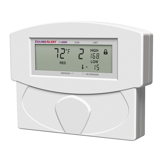
Page 42: Normal (Non-Alarm) Mode Display
Normal (Non-Alarm) Mode Display An example of a running display for a Zone programmed to monitor temperature is shown below. In general, normal non-alarm indication for any mode shows: The measured data pertaining to the Zone. No flashing data. (Alarm) icon. Alarm Mode Displays An example of a Alarm Display is shown below. -
Page 43: Viewing Alarm History
An alarm indication for any mode is shown by: Flashing data corresponding to the Zone where the alarm is occurring. (Alarm) icon will flash during an alarm, and is solid if time delay is activated. When time delay expires, icon will flash indicating an output relay has been activated for the Zone in alarm. -
Page 44: Troubleshooting
Press the DECREASE key to go to the next stored alarm. The next alarm is displayed as described in step 1. Press ALARM HISTORY to go back to the normal display. Clear the alarm history by pressing and holding the ALARM HISTORY key until (Clear) is displayed, then release the key. - Page 45 “Red” sensor is used, make cer- played for nominal actual tain Zone is set for RED °F or RED temperature of 80° F). °C.) ERR displayed EA200 / EA400 internal Contact Winland Technical Service calibration error at 1-800-635-4269. D-011-0093...
-
Page 46: Accessories
Accessories Note: In the table below, “Sensor Type Setting” specifies the appropriate sensor type selection to be entered during Zone programming for the sensor type listed. Where an accessory does not pertain to sensor type, this is denoted by “N/A” (not applicable). - Page 47 Accessories — continued Item (Model Number) Description Sensor Type Setting Waterproof Thermistor –50° C to 70° C (–58° F to 158° F) Low-Temp (“Blue”) Accuracy: +/-2°F setting Sensor (TEMP-L-W) 0° C to 105° C (32° F to 221° F) Waterproof Thermistor High-Temp (“Red”) Accuracy: +/-2°F setting...
- Page 48 Accessories — continued Item (Model Number) Description Sensor Type Setting Other Accessories Audible Alarm Buzzer that can be connected to Module auxiliary relay output to provide audi- ble alert of alarm (1.5 to 24VDC). (BZ-1) 3-piece Terminal Block Adapts stripped wire ends to the Adapter Kit header connector pins on EA200 / EA400 printed circuit board.
-
Page 49: Specifications
Specifications Specifications Item EA200 EA400 Dimensions Approximately 122 mm x 152 mm x 30.5 mm (4.8” H x 6.0” W x 1.2” D) Weight 0.25 kg (0.55 lb.) 0.27 kg (0.6 lb.) Mounting Mountable directly to 2-gang standard electrical enclosure using pre-drilled holes on EA200 / EA400 rear case. - Page 50 (using built-in temperature (wired) sensors correspond- sensor) ing to Zones 1 through 4. • (1) Connector for external Usable with Winland tempera- (wired) sensor ture, humidity, or water pres- corresponding to Zone 2. ence sensors (see • Usable with Winland “Accessories”...
- Page 51 Specifications — continued Item EA200 EA400 Sensor Type/Connection: • Temperature: 2-wire, 18-22AWG; maximum 304 m (1000 ft.) cabling length 3-wire, 18-22AWG; maximum 304 m (1000 ft.) cabling length • Humidity: 2-wire, 18-22AWG; maximum 304 m (1000 ft.) cabling length • Water Presence: Minimum Span Between High and •...
- Page 52 Specifications — continued Item EA200 EA400 Device Environmental Operating Range: • Humidity: 5 to 95% RH, non-condensing 0°C to 50°C (32° F to 122° F). Not for installation inside of • Temperature, Operating: coolers or freezers. • Ambient Environmental Quality: Indoor use intended, non-corrosive environment Conformity Certifications See page 52...
-
Page 53: Warranty And Service Information
Under no circumstances shall Winland’s liability under this limited warranty exceed the purchase price paid by the end user/purchaser for the product. No person, agent or dealer is authorized to give warranties on behalf of Winland nor to assume for Winland any other liability in connection with any of its products. -
Page 54: Weee Product Recovery/Recycling For Eu Customers
Directive, Winland Electronics must take back waste electrical or electronic equipment covered under the WEEE Directive, at its cost, for all product it puts on the market after July 1, 2006. The Return Process: Contact Winland via our website at www.winland.com and go to the WEEE link on the home page. - Page 55 Directive, Winland Electronics must take back waste electrical or electronic equipment covered under the WEEE Directive, at its cost, for all product it puts on the market after July 1, 2006. The Return Process: Contact Winland via our website at www.winland.com and go to the WEEE link on the home page.
- Page 56 D-011-0093 Rev. C Manufactured in the U.S.A by Winland Electronics 1950 Excel Drive, Mankato, MN, 56001 Outside MN Phone: 1-800-635-4269 Phone: 507-625-7231 Fax: 507-387-2488 ©Winland Electronics, Inc. 2005 www.winlandsecurity.com...
Need help?
Do you have a question about the EnviroAlert EA200 and is the answer not in the manual?
Questions and answers