Table of Contents
Advertisement
This manual contains operating instructions and maintenance schedules for the high pressure breathing air compressors. Operators
must read and understand all information inside the manual.
ATTENTION. This machine can be used only after a careful reading of this instruction manual. The machine may only
used to produce compressed air. Other use is strictly prohibited. The manufacturer and the supplier void all responsibility
for damage or injury resulting from failure to follow these instructions.
Before using the machine please put your attention to this
general information:
1. Personnel engaged to operate the machine must have read the
instruction manual before beginning work, especially the safety
notices chapter.
2. Personnel may not wear long hair loose, loose clothing or
jewellery, including rings.
3. Keep all safety and danger notices on the unit complete and in
readable condition.
4. No modifications may be made to the unit which could impair
safety without first obtaining permission from the suppliers.
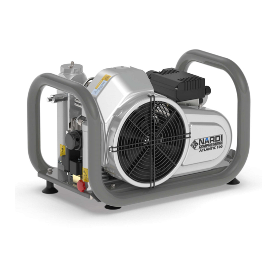
The ATLANTIC 100 high pressure compressors are designed to
compress air for breathing as required in diving and fire fighting
applications. The max pressure is 225 bar or 330 bar depending
on unit.
The compressor unit comprises the following major assemblies:
Il compressore è composto da:
. Compressor block
. Electric or petrol/diesel engine
. Filters
The compressor block ATLANTIC 100 is used to compress air in the high pressure range up to 330 bar (4500 psi). The compressor
block is of a four stage, four cylinders design. The cylinders are arranged in the 1st stage on the left, 2nd stage on the right, 3rd and
4th stage on the centre side looking from the filter side. The compressor blocks are particularly suitable for continuous operation
because of their rugged design and the corrosion resistant intermediate filter and cooler assemblies. Smooth running is a particular
feature of this Nardi design. The moving parts of the driving gear are all equally balanced. This results in a vibration-free running. The
driving gear is fitted with energy saving cylinder roller bearings. The upper and lower connecting rod bearings are also roller bearings.
Crankcase, cylinders and heads are obtained from the gravity dies. Connecting rod are extracted from casting dies. Cylinder are in cast
iron inside an aluminium pipe.
Instruction Manual
ATLANTIC 100
1. GENERAL INFORMATION:
5. Piping must be thoroughly checked (pressure and visual inspection)
by the operator at appropriate time intervals, even if no safety related
faults have been noticed..
6. Intervals stipulated or given in the instruction manual for recurring
checks/inspections must be adhered to.
7. It is absolutely essential that the workplace is appropriately
equipped for maintenance measures.
8. Work on/with the unit may only be carried out by reliable personnel.
Observe the legal minimum age permissible.
2. GENERAL INTRODUCTION:
. Filling assembly
. Protection and anti-vibration frame
. Automatic condensate drain*
. Electric control system**
. Automatic switch on/off*
. ALLUMINUM frame
(*) Optional extra according to order
3. COMPRESSOR PUMP UNIT
Page 1
Advertisement
Table of Contents

Related Manuals for nardi atlantic 100


Summary of Contents for nardi atlantic 100
- Page 1 3. COMPRESSOR PUMP UNIT The compressor block ATLANTIC 100 is used to compress air in the high pressure range up to 330 bar (4500 psi). The compressor block is of a four stage, four cylinders design. The cylinders are arranged in the 1st stage on the left, 2nd stage on the right, 3rd and 4th stage on the centre side looking from the filter side.
- Page 2 Instruction Manual Page 2 ATLANTIC 100 Description Intake Filter 1st stage Inter-cooler 1st stage 2nd stage Inter-cooler 2nd stage 3rd stage Inter-cooler 3rd stage 4th stage Inter-cooler 4th stage 10. Oil indicator 4. TECHNICAL DATA Compressor unit ATLANTIC 100 Operating pressure...
- Page 3 Observe switching on and off processes and monitoring indications according to the instructions manual. - Use only Nardi original parts and equipments. - Drain the valve regularly if manual drain valve. Check every ten minutes the valve if automatic drain valve.
- Page 4 Instruction Manual Page 4 ATLANTIC 100 6.2. Starting the unit: Unit with electric engine without compressor control system: The motor is switched on manually by pressing the start button. Machine does not be left alone during working. Check continuosly the right function.
- Page 5 Instruction Manual Page 5 ATLANTIC 100 8.2. Maintenance schedule: After first 25 operating hours Date Segnature Clean intake filter and intake filter cartridge Check Oil level ( Max. RED POINT ) Cartuccia Filtro Carboni – setaccio Check tightness of all cooler-pipes and couplings...
- Page 6 9.2. Type of oil : Using the correct oil is of vital importance for life and maintenance of the compressor. Nardi has a particular oil studied and tested for the best operation of his machine. Depending on the application of the compressor the requirements placed on the oil are:...
- Page 7 To avoid any ranger to your health or damage to your unit, change used up cartridges in good time. Never fill used up cartridges yourself. The filter material was chosen specifically by Nardi compressori for each kind of application. Never remove replacement cartridge from packaging prior to actual use otherwise highly sensitive molecular sieve will absorb water vapour from surrounding air and cartridge saturated.
- Page 8 Instruction Manual Page 8 ATLANTIC 100 9.11. Valves: The valve heads of the individual stages form the top part of Observe the correct sequence when fitting together again. the cylinders. The intake and pressure valves are fitted inside Check individual components for excessive wear. If the valve seat the valve heads.
- Page 9 Instruction Manual Page 9 ATLANTIC 100 Space Parts ATLANTIC 100: N° Pasts Description Quantity N° Pasts Description Quantity N° Description Quantity A001 Metal Cover Fan A020 Compressor crankcase A039 Safety O-ring piston 1st – 2nd A002 A021 Thickness A040 Piston 1st stage...
- Page 10 Instruction Manual Page 10 ATLANTIC 100 Space parts ATLANTIC 100: N° Descriptor Quantity N° Description Quantity N° Description Quantity A057 O-ring A077 Connections L 1/4'' tube 8mm A095 Screw A058 Cylinder 1st Stage A078 Inferior body valve 2 stage A096...
- Page 11 Instruction Manual Page 11 ATLANTIC 100 Space parts ATLANTIC 100: N° Description Quantity N° Description Quantity A113 Intercooler 1 – 2 Stage A121 Intercooler 3 Stage – separator A114 Fixing tube 1 – 2 Stage A122 Fixing tube 3 - separator...
- Page 12 Instruction Manual Page 12 ATLANTIC 100 Space parts ATLANTIC 100: N° Description Quantity N° Description Quantity N° Description Quantity mpres. A128 Connection L 1/4'' tube 8mm A143 Plug filter separator Inferior A157E60HZ Belt for electric engine 60 Hz A129 Screw...
Need help?
Do you have a question about the atlantic 100 and is the answer not in the manual?
Questions and answers