Table of Contents
Advertisement
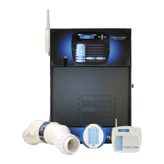
Aqua Logic Programming Flow Chart
PS-4 only
PS-4 only
G
LD
LINE
C
ON TROLS
North Kingstown, RI 02852 USA
denotes conditional items
092042H
Copyright © 2008 Goldine Controls
Aqua Logic
Aqua Logic
Aqua Logic
Aqua Logic
Aqua Logic
Automation and Chlorination
(actuators, cell & remote display not included - order separately)
Installation Manual
for models
AQL-PS-4
AQL-PS-8
AQL-PS-16
G
LD
LINE
C
ON TROLS
AQL-PS-8-V
AQL-PS-16-V
www.goldlinecontrols.com
888-921-7665
Advertisement
Table of Contents

Related Manuals for Aqua Logic AQL-PS-4

Summary of Contents for Aqua Logic AQL-PS-4
- Page 1 Aqua Logic Programming Flow Chart Aqua Logic Aqua Logic Aqua Logic Aqua Logic Aqua Logic denotes conditional items Automation and Chlorination PS-4 only (actuators, cell & remote display not included - order separately) Installation Manual for models AQL-PS-4 AQL-PS-8-V AQL-PS-8...
-
Page 2: Important Safety Instructions
If written proof of the date of the initial system installation is not IMPORTANT SAFETY INSTRUCTIONS provided to Goldline, the manufacturing datecode on the Aqua Rite, Aqua Rite Pro, Aqua Trol, Aqua Logic and Pro Logic electronics unit will be the sole determinant of the date of the initial system installation. -
Page 3: Table Of Contents
The following statement is applicable if any of the wireless accessories are connected to the Aqua Logic system. Table of Contents FCC Statement (Compliance Statement, Part 15.19): This device complies with Part 15 of the FCC Rules. Operation is subject to the following two conditions: (1) This device may not cause harmful interference, and (2) this device must accept any interference received, including interference that may cause undesired operation. -
Page 4: Before You Begin
Before You Begin 1. Check that the Aqua Logic is calling for the heater to turn on as indicated by the “Heater” LED being illuminated. If the “Heater” LED is illuminated, go directly to step 2; if not, then check the following: What’s Included... -
Page 5: Installation Steps
6. System Startup and checkout (page 36) Before Startup Before starting the Aqua Logic for the first time, be sure that the following items have been completed: 1. Pool/spa chemicals are within the recommended levels according to the chart on page 3. -
Page 6: General Water Chemistry
Select 6B Spa Rotates between all available remotes Salt is required only if you are using the chlorinator features on the Aqua Logic Control. If you are NOT > using the chlorinator, it is recommended that you follow all of the other chemistry recommendations be- Move to next menu item sides salt. -
Page 7: Salt
NOTE: If the pool does not have new water, add metal remover and non-copper based algaecide Valve3 Function to the pool, per manufacturer’s instructions. This ensures a quick, troublefree transfer to the Aqua Logic Manual On/Off (default) – the valve3 relay will alternate between turning on and off when system. - Page 8 (1.3) (1.4) (1.5) The Aqua Logic allows you to assign any one of a number of names (e.g. “Cleaner Valve, 80 ppm Waterfall valve, Solar Valve, etc.) to each of the valve output control function. This will make the Aqua Logic much more user friendly to the homeowner when they want to turn various valves on or off or program the timeclocks.
-
Page 9: Aqua Logic Control Center
Because the enclosure also acts as a heat sink (disperses heat from inside the box), it is proper operation to occur. important not to block the four sides of the control. Do not mount the Aqua Logic inside a panel or tightly enclosed area. -
Page 10: Optional Wired Remote Display/Keypad
Aux1 Group Rotates between Manual On/Off (default),Countdown Timer and Timeclock Timer: None(Manual) A single Base Station must be installed on the Aqua Logic in order to use any of the Goldline wireless > Move to next configuration menu item remote controls. With the Base Station installed, there is no limit on the number of wireless remotes that... -
Page 11: Optional Base Station
BASE-RF for AQL remote controls or AQL2-BASE-RF for AQL2 remote controls. To install the base station, remove the knockout on the upper left side of the Aqua Logic main control unit, insert the base When activating Group functions, be aware that the most recent Group function that is station, and then tighten the nut from the inside. -
Page 12: Standard" Pool/Spa Configuration
CHECK VALVE HEAT VALVE HEATER Low Speed of a 2-speed Filter Pump – the Aqua Logic will turn on the lights relay whenever POOL/SPA SUCTION PUMP VALVE FILTER the low speed operation of the filter pump is required. It is very important that the “2-speed”... -
Page 13: Dual Equipment" Pool/Spa - Separate Heaters
The Heater1 output should be connected to the spa heater—the heater will only turn on The Aqua Logic allows you to assign any one of a number of names (e.g. “Pool Light, Spa when the spa filter pump is running. -
Page 14: Dual Equipment" Pool/Spa - Shared Heaters
6. The chlorinator cell must be installed in the pool plumbing. If spillover is enabled, then the Aqua enabled, the Aqua Logic will continue to run the filter pump for 5 minutes after the heater turns off. During this period the filter pump LED will flash and also a “Heater Cooldown, Logic can chlorinate both the pool and spa (during spillover operation). -
Page 15: Turbo Cell
Goldline flow switch, the Aqua Logic monitors the state of water flow when the filter pump is temperature whenever the “Spa Filter” pump is running. on. If no flow is detected for more than 15 minutes, the Aqua Logic will shut down the pool 4. Solar heater control is NOT available for dual equipment systems. -
Page 16: Main Service
Grounding and Bonding Freeze Protect Toggle between Enabled (default) and Disabled Freeze Protection Connect a ground wire from the primary electrical panel to the Aqua Logic ground bus bar. Also ground Enabled > Move to next menu item or previous/next configuration menu each piece of high voltage (120 or 240VAC) equipment that is connected to the Aqua Logic control relays if “Freeze Protect”... -
Page 17: General Purpose Outlet
Rotates between Pool and Spa-Std (default) , Pool and Spa-Dual, knockouts on the lower right side of the Aqua Logic enclosure. Per code, the receptacle should be a Pool/Spa Setup Pool Only, and Spa Only options GFCI type. Alternatively, connect a standard receptacle to a GFCB. -
Page 18: Low Voltage Wiring
“Heater2” except for the terminal connections at the Aqua Logic control. The Aqua Logic provides a set of low voltage dry contacts that can be connected to most gas heaters or heat pumps with 24V control circuits. Refer to the diagram on the following page for a generic connection. -
Page 19: Configuration Menus
Goldline Tech support, 888-921-7665. Refer to the diagrams and the information on the follow- Aqua Logic is configured. For example, if the Aqua Logic is configured for a single heater, “Heater2” will not be available as an option in the Group menu. Also, under some circumstances, functions will be ing pages for more details on the connection to several popular heaters. -
Page 20: Configuration Setup
3. Leave jumper attached to terminals 4 & 5. The latest version of the Aqua Logic offers the ability to assign a Group function to a particular button. 4. Move “BYPASS” dipswitch on heater circuit board to “ON” position (up). - Page 21 Aqua Logic. Some homeowners see the “OFF” display and, thinking this is a mistake, change BLACK Jumper Removed the mode to “POOL” or “SPA” which then disables the remote control by the Aqua Logic. To Jumper Installed For Secondary(s) For Primary prevent this: Remove the heater touch pad connector (P5) which will disable the touchpad.
- Page 22 The Aqua Logic main unit can connect to a maximum of 3 remote wired display/keypads. One remote Control Center as shown below. Note that the terminals on both the Aqua Logic main unit and the PS-16 wired display/keypad is included with the Aqua Logic, additional wired display/keypads must be ordered Expansion Unit are numbered: Connect 1 to 1, 2 to 2, etc.
Need help?
Do you have a question about the AQL-PS-4 and is the answer not in the manual?
Questions and answers