
Related Manuals for McIntosh MC122


Summary of Contents for McIntosh MC122
- Page 1 OWNER’S MANUAL MC122 Power Amplifier MC122 McIntosh Laboratory, Inc. 2 Chambers Street Binghamton, New York 13903-2699 Phone: 607-723-3512 FAX: 607-724-0549...
-
Page 2: Purchase Date
Thank You Table of Contents Please Take A Moment NOTES: 1. Connecting Cables are available from the McIntosh Parts Department: Data and Power Control Cable Part No. 170-202 Six foot, shielded 2 conductor, with 1/8 inch stereo mini Serial Number: phone plugs on each end. -
Page 3: Important Safety Instructions
Safety Instructions IMPORTANT SAFETY Attention: pour pevenir les chocs elecriques pas INSTRUCTIONS! utiliser cette fiche polarisee avec un prolongateur, une prise de courant ou un autre sortie de courant, sauf si les lames peuvent etre inserees afond ans en PLEASE READ THEM BEFORE laisser aucune partie a decouvert. - Page 4 Safety Instructions con’t, Introduction and Performance Features Introduction Care of Equipment: Performance Features · Power Output · Repair of Equipment: High Current Output · Power Guard · Sentry Monitor · Thermal Protection · Convenient Hookup · Power Control...
-
Page 5: Installation
Installation Installation 17-1/2" 444mm 7/32" 17-1/16" 5.3mm 433.4mm 1/4" Outline of Front Panel Edge of Cutout End Caps Panel Height 3-1/16" 3-9/16" 3 1/2" 77.8mm (Front View) 90.0mm 88.9mm 3/16" 5.1mm Support Shelf Bottom of Cutout and Top of Support Shelf Must Coincide Mounting Surface Mounting Bracket at Both Sides of the Rear Panel. - Page 6 MC122 Rear Panel Controls and Connections MC122 Rear Panel Controls and Connections Connect the MC122 power Input LEVEL controls cord to a live AC outlet. Refer for Right and Left to information on the back channels panel to determine the correct...
- Page 7 How to Connect the MC122 How to Connect the MC122 McIntosh C15 Preamplifier To AC Outlet 1 2 3 4 5 6 7 8 9 1 2 3 4 5 6 7 8 9 1 2 3 4 5 6 7 8 9...
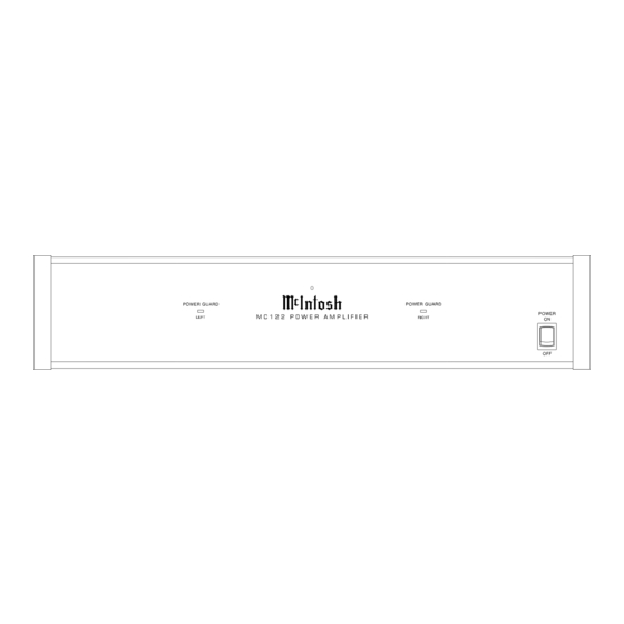
- Page 8 MC122 Front Panel Displays and Switch MC122 Front Panel Displays and Switch Power On Indicator POWER GUARD LED’s POWER Switch Turns light when the amplifier AC power on/off, or on/ channel POWER GUARD remote circuit activates...
- Page 9 How to Operate the MC122 Input Level Controls Figure 1 Power On Note: The MC122 Power Switch must be left in the On position and there must be a power control connection in order for the remote power turn on to function.
-
Page 10: Specifications
Specifications Specifications Power Output Per Channel Power Requirements Output Load Impedance NOTE: Refer to the rear panel of the MC122 for the correct Rated Power Band voltage Dimensions Dynamic Headroom Frequency Response Weight Total Harmonic Distortion Intermodulation Distortion Signal To Noise Ratio... - Page 11 Packing Instructions Packing Instructions...
Need help?
Do you have a question about the MC122 and is the answer not in the manual?
Questions and answers