Table of Contents
Advertisement
Advertisement
Table of Contents

Related Manuals for McIntosh MAC 1900


Summary of Contents for McIntosh MAC 1900
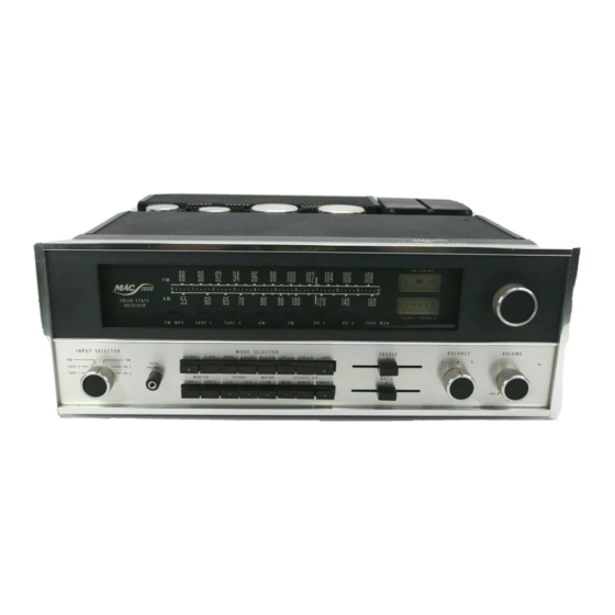
- Page 1 THE MAC 1900 SOLID STATE AM FM/FM STEREO RECEIVER Price $1.25...
-
Page 3: Table Of Contents
Your MAC 1900 AM-FM/FM stereo receiver will give you many years CONTENTS of pleasant and satisfactory performance. If you have any questions concerning Guarantee . . . the operation or maintenance of Installation . . . this receiver please contact: How to Connect . -
Page 4: Installation
Make sure that the bottom of the template rests on the shelf on which the MAC 1900 will sit. Mark the two locating holes ("B" holes on the mounting template). -
Page 5: How To Connect
How to Connect 1. CONNECTING TAPE RECORDERS To Record: Connect a cable from the L TAPE OUT 1 jack to the left high level input of a tape recorder. Connect a cable from the R TAPE OUT 1 jack to the right high level input of the tape recorder. Connect a second tape recorder in the same way to the L and R TAPE 2 OUTputs. -
Page 6: Record Players
An unbalanced 75 ohm antenna can be connected The MAC 1900 has been shipped with shorting to the MAC 1900. A "type F" connector is used to plugs in the phono inputs. Remove the shorting connect the 75 ohm coaxial cable to the back panel plugs only from the jack that will be used. -
Page 7: Antenna
Connecting - Record Players Maximum Performance Indicator Antenna and Ground FM ANTENNA OPTIONAL 75 FM ANTENNA INPUT MAXIMUM GROUND TO PERFORMANCE WATER PIPE INDICATOR OR ROD IN EARTH RECORD CHANGER OR TURNTABLE TURNTABLE RECORD CHANGER... -
Page 8: Loudspeakers
MAIN loudspeaker to the CONNECTING LOUDSPEAKERS: RIGHT MAIN SPEAKER push connector. Use lamp The MAC 1900 Power Amplifier is designed for cord, bell wire, or wire with similar type of insulation stereo connection only. Do not connect the MAC to connect the speakers to the amplifier. - Page 9 CONNECTING REMOTE 1 REMOTE 1 REMOTE 2 REMOTE 2 RIGHT LEFT LEFT RIGHT MCINTOSH SPEAKER SPEAKER SPEAKER SPEAKER LOUDSPEAKERS WITH THE ENVIRONMENTAL EQUALIZER MQ101 ENVIRONMENTAL EQUALIZER LEFT SPEAKER RIGHT SPEAKER...
-
Page 10: What The Controls Do And How To Use Them
TONE CONTROLS: fication. TAPE 2: Connects the output from a tape recorder The tone controls on the MAC 1900 are slide con- that has its own playback electronics to the high trols with a center detent to indicate the flat posi- level amplifying stage of the MAC 1900. -
Page 11: Using The Tuning Dial
The higher the indication, the stronger source signal from either of two tape recorders used is the signal. For AM tune for the maximum indication with the MAC 1900. The recorders used with the MAC on the meter. 1900 should have separate record and playback heads and separate record and play amplifiers. - Page 12 Example: Connect the output of recorder 1 to TAPE MONITOR 1 input on the MAC 1900. Connect the TAPE 1 OUTput on the MAC 1900 to the input of recorder 1. In the same way, connect the output of FILTERS recorder 2 to TAPE MONITOR 2 input on the MAC 1900.
-
Page 13: Balancing Your Stereo
leads on one of the loudspeakers only. When justed to optimum at the factory using precision test the sound comes from the midpoint between the instruments. speakers they are in PHASE. OUT . . . MUTING disconnected. TO BALANCE LOUDNESS IN . -
Page 14: Performance Limits
19,000 Hz pilot carrier. This signal causes the Tuner: 1.0 volt automatic circuit to switch the MAC 1900 to stereo. If Tape: 250 mV with rated input from low level in- a station is not broadcasting a 19,000 Hz pilot signal... - Page 15 verse, Stereo, Mono, L+R, L+R to right speaker only, HARMONIC DISTORTION: Does not exceed 1% at and L+R to left speaker only. 30% modulation TAPE MONITOR: Two pushbutton switches. Either of FREQUENCY RESPONSE: 3500 Hz at —6 dB down two tape recorders can be monitored by selecting ADJACENT CHANNEL SELECTIVITY: 30 dB mini- the TAPE MON.
-
Page 19: Technical Description
200 ohms. The millivolts without overload, a voltage far greater than output is fed to jacks on the rear at the MAC 1900. In the output of any current magnetic phono cartridge. the normal operation, both filters out, the filter am- Phono input overload is virtually impossible. - Page 20 It is a high voltage full automatic sensing device turns the AC power off to wave rectified and filtered supply. the MAC 1900. The MAC 1900 will turn on again when the temperature has returned to normal limits. This Two additional electronically regulated power additional protection assures you of the complete supplies are used in your MAC 1900.
- Page 21 This extreme shielding gives protection against radiation or interference. The SCA (Subsidiary Communication Authoriza- The RF circuits of the MAC 1900 exceed the FCC re- tion) signal must be removed from the composite quirements for suppression of oscillator radiation.
- Page 22 A high-quality loopstick antenna is provided. It can be rotated for maximum performance, optimum signal rejection or minimum interference. In each MAC 1900 the loopsticks are individually tuned for optimum performance. After tuning the loopstick is then sealed. This custom matching of the loopstick to the AM-RF front end maximizes the performance of the loopstick antenna.
-
Page 23: Block Diagram
Block Diagram... - Page 24 McINTOSH LABORATORY INC. 2 CHAMBERS ST., BINGHAMTON, N. Y. 13903 607-723-3512 Design subject to change without notice. Printed in U.S.A. 038-674...
Need help?
Do you have a question about the MAC 1900 and is the answer not in the manual?
Questions and answers