Table of Contents
Advertisement
INSTALLATION
INSTRUCTION
CONTENTS
GENERAL INFORMATION. . . . . . . . . . . . . . . . . . . . . . . . . 3
UNIT INSTALLATION. . . . . . . . . . . . . . . . . . . . . . . . . . . . . 5
VENTING. . . . . . . . . . . . . . . . . . . . . . . . . . . . . . . . . . . . . . . 6
UPFLOW/HORIZONTAL MODELS - . . . . . . . . . . . . . . . . 10
FILTERS INSTALLATION . . . . . . . . . . . . . . . . . . . . . . . . 10
UPFLOW/HORIZONTAL MODELS - . . . . . . . . . . . . . . . . 11
DOWNFLOW MODEL APPLICATION . . . . . . . . . . . . . . . 12
OPERATION AND MAINTENANCE. . . . . . . . . . . . . . . . . 23
TROUBLESHOOTING . . . . . . . . . . . . . . . . . . . . . . . . . . . 26
FURNACE ACCESSORIES . . . . . . . . . . . . . . . . . . . . . . . 28
SEQUENCE OF OPERATION . . . . . . . . . . . . . . . . . . . . . 29
WIRING DIAGRAM - UPFLOW / HORIZONTAL . . . . . . . 30
WIRING DIAGRAM - DOWNFLOW . . . . . . . . . . . . . . . . . 31
CAUTION: READ ALL SAFETY GUIDES BEFORE YOU
START TO INSTALL YOUR FURNACE.
SAVE THIS MANUAL
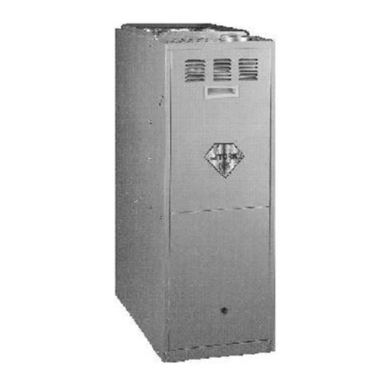
TWO-STAGE
MID-EFFICIENCY GAS-FIRED
TUBULAR HEAT EXCHANGER SERIES
MODELS: P*DU & G8D-UH (Upflow / Horizontal)
P*DD & G8D-DN (Downflow)
57 - 120 MBH INPUT
FOR YOUR SAFETY
WHAT TO DO IF YOU SMELL GAS
•
Do not try to light any appliance.
•
Open windows.
•
Do not touch any electrical switch;do not use any phone in
your building.
•
Extinguish any open flame.
•
Immediately call your gas supplier from a neighbor's phone.
Follow the gas supplier's instructions.
•
If you cannot reach your gas supplier, call the fire depart-
ment.
FOR YOUR SAFETY
Do not store or use gasoline or other flammable vapors and liq-
uids in the vicinity of this or any other appliance.
035-14527-000 REV A (599)
Form 650.77-N3U
Advertisement
Table of Contents

Subscribe to Our Youtube Channel
Related Manuals for Luxaire P*DU & G8D-UH series


Summary of Contents for Luxaire P*DU & G8D-UH series
-
Page 1: Table Of Contents
INSTALLATION TWO-STAGE MID-EFFICIENCY GAS-FIRED INSTRUCTION TUBULAR HEAT EXCHANGER SERIES MODELS: P*DU & G8D-UH (Upflow / Horizontal) P*DD & G8D-DN (Downflow) 57 - 120 MBH INPUT CONTENTS GENERAL INFORMATION......3 UNIT INSTALLATION. - Page 2 035-14527-000 REV A (599) Form 650.77-N3U CONTENTS GENERAL INFORMATION ......3 DESCRIPTION ........3 INSPECTION .
-
Page 3: General Information
035-14527-000 REV A (599) Form 650.77-N3U GENERAL INFORMATION damage may occur if installation procedures are not handled properly. DESCRIPTION This Category I furnace is designed for installation in a resi- dential or commercial application. A Category I furnace has a fan assisted combustion system equipped with an integral Each furnace in this series is a Category I furnace, mechanical means to draw products of combustion through... - Page 4 035-14527-000 REV A (599) Form 650.77-N3U Check the rating plate and power supply to be sure that elec- Where it will not interfere with proper air circulation in the trical characteristics match. All models use nominal 115 vac, confined space. 1phase, 60 Hz.
-
Page 5: Unit Installation
035-14527-000 REV A (599) Form 650.77-N3U UNIT INSTALLATION NOTE: Ducts must have the same cross-sectional area as the free area in the opening to which they are connected. The minimum dimension of rectangular ducts shall be three COMBUSTION AIR inches. All installations must comply with Section 5.3, Air for Com- One permanent opening, commencing within 12 inches bustion and Ventilation of the National Fuel Gas Code, ANSI... -
Page 6: Venting
035-14527-000 REV A (599) Form 650.77-N3U Combustion Air Quality VENTING The recommended source of combustion air is to use the out- door air supply. Excessive exposure to contaminated com- bustion air will result in safety and performance related problems. However, the use of indoor air in most applications is acceptable, except as follows: It is the responsibility of the installer to verify proper vent system operation. - Page 7 035-14527-000 REV A (599) Form 650.77-N3U Models P*DU & G8D—UH 57 / 46 / 800 / “A” 14-1/2 13-1/4 10-1/8 10-1/8 4-3/16 80 / 64 / 1200 / “A” 14-1/2 13-1/4 10-1/8 10-1/8 3-3/4 80 / 64 / 1600 / “B” 17-1/2 16-1/4 13-1/8 11-5/8...
- Page 8 035-14527-000 REV A (599) Form 650.77-N3U Models P*DD & G8D—DN 57 / 46 / 800 / “A” 14-1/2 13-1/4 12-1/4 10-1/8 4-3/16 80 / 64 / 1200 / “A” 14-1/2 13-1/4 12-1/4 10-1/8 3-3/4 80 / 64 / 1600 / “B” 17-1/2 16-1/4 15-1/4...
-
Page 9: Vent Safety Check Procedure
035-14527-000 REV A (599) Form 650.77-N3U VENT SAFETY CHECK PROCEDURE If improper venting is observed during any of the above tests, the venting system must be corrected. Any corrections or resizing of the common venting sys- tem must be in accordance with the National Fuel Gas Code, ANSI Z223.1 or Section 7, Venting Systems and Air Supply for Appliances, CAN/CGA B149.1 or.2 Instal- If this furnace is replacing a common-vented fur-... -
Page 10: Upflow/Horizontal Models
035-14527-000 REV A (599) Form 650.77-N3U UPFLOW/HORIZONTAL MODELS - UPFLOW APPLICATION Supply Plenum Connection Attach the supply plenum to the fur- nace outlet duct connection flanges. This is typically through the use of S cleat material when a metal plenum is used. -
Page 11: Upflow/Horizontal Models
035-14527-000 REV A (599) Form 650.77-N3U Side Return - External Filter Bottom Return Locate and knock out the square corner locators. These indi- Bottom return applications normally pull return air through a cate the size of the cutout to be made in the furnace side base platform or return air plenum. -
Page 12: Downflow Model Application
035-14527-000 REV A (599) Form 650.77-N3U ATTIC INSTALLATION Angle supports should be placed at the supply air end and near the blower deck. (Refer to Figure 7 on page12). Do not support at return air end of unit. This appliance is design certified for line contact for furnaces installed horizontally. -
Page 13: Supply Air Ducts
035-14527-000 REV A (599) Form 650.77-N3U This base can be replaced with a matching cooling coil, prop- erly sealed to prevent leaks. Follow the cooling coil instruc- tions on page23 for installing the plenum. GAS PIPING NOTE: An accessible manual shutoff valve must be installed upstream of the furnace gas controls and within 6 feet of the furnace. -
Page 14: Electrical Power Connection
035-14527-000 REV A (599) Form 650.77-N3U nections to the unit. Installation of a drop leg and ground Code ANSI/NFPA No. 70 - latest edition, Canadian Electric Code C22.1 Part 1 - (latest edition) and/or local codes. Elec- union is required. (Refer to Figure 10 on page14) trical wires which are field installed shall conform with the temperature limitation for 63°F/35°C rise wire when installed in accordance with instructions. - Page 15 035-14527-000 REV A (599) Form 650.77-N3U disconnected, complete the low-voltage wiring from the ther- mostat to the terminal board on the low-voltage transformer. Connect Class 2 control wiring for single stage thermostat wiring (Refer to Figure 13 on page15) or for two stage ther- mostat wiring (Refer to Figure 14 on page15)..
-
Page 16: Safety Controls
035-14527-000 REV A (599) Form 650.77-N3U adjustments. Follow the thermostat manufacturer's instruc- Pressure Switch: This furnace is supplied with two differen- tions. tial pressure switches which monitor the flow through the fur- nace and venting system. This switch de-energizes the The 24-volt, 40 VA transformer is sized for the furnace com- ignition control module and the gas valve if any of the follow- ponents only, and should not be connected to auxiliary... -
Page 17: Ignition System Checkout/Adjustment
035-14527-000 REV A (599) Form 650.77-N3U stop the leaks. If the leak persists, replace the compo- nent. DO NOT omit this test! NEVER use a flame to check for gas leaks. CHECKING GAS INPUT Turn off all other gas appliances connected to gas meter. LOW FIRE With the furnace turned on, measure the time needed for REGULATOR... -
Page 18: Adjustment Of Manifold Gas Pressure
035-14527-000 REV A (599) Form 650.77-N3U in your particular locality. Contract your gas company for this To increase outlet pressure, turn the 3/32" socket set information, as it varies widely from city to city. screw below the low adjustment seal screw clockwise. To decrease outlet pressure, turn the set screw counter- EXAMPLE: It is found by measurement that it takes 26 sec- clockwise. -
Page 19: Adjustment Of Temperature Rise
035-14527-000 REV A (599) Form 650.77-N3U Turn the electrical and gas supplies back on, and, with the burners in operation, check for gas leakage around the plug with a soap and water solution. Be sure that the gas valve pressure regulator cap is replaced. -
Page 20: Accessory Connections
035-14527-000 REV A (599) Form 650.77-N3U ACCESSORY CONNECTIONS The furnace control will allow power switching control of vari- ous accessories. (Refer to Figure 17 on page20) for con- nection details. Electronic Air Cleaner Connection Two 1/4" spade terminals (EAC and EAC N) for electronic air cleaner connections are located on the control board. - Page 21 035-14527-000 REV A (599) Form 650.77-N3U BLOWER PERFORMANCE - UPFLOW/HORIZ. (MODELS P*DU & G8D-UH) CFM-INCLUDES FILTER(S) NOTE: Data below reflects air flows with single return opening, either left or right side or bottom. EXTERNAL STATIC PRESSURE, INCHES W.C. SPEED MODEL HIGH FIRE INPUT SHOWN 0.10...
- Page 22 035-14527-000 REV A (599) Form 650.77-N3U BLOWER PERFORMANCE - DOWNFLOW (MODELS P*DD & G8D-DN) CFM-INCLUDES FILTER(S) NOTE: Data below reflects air flows with single return opening, either left or right side or bottom. EXTERNAL STATIC PRESSURE, INCHES W.C. MODEL HIGH SPEED FIRE INPUT 0.10...
-
Page 23: Operation And Maintenance
035-14527-000 REV A (599) Form 650.77-N3U OPERATION AND MAINTENANCE pressure switch contacts will close and energize the second stage gas valve (high fire). SEQUENCE OF OPERATION If a call for second stage heat occurs at the same time as a call for first stage heat, the second stage heat is energized as The following describes the sequence of operation of the fur- above. -
Page 24: Maintenance
035-14527-000 REV A (599) Form 650.77-N3U If the control has gone into system lockout, it may be possible Upflow / Horizontal Installations to reset the control by a momentary power interruption of one Turn off electrical power supply to the furnace at discon- second or longer. -
Page 25: Cleaning The Heat Exchanger
035-14527-000 REV A (599) Form 650.77-N3U Note the wire/terminal location and then remove the cleaned by rinsing in hot water or by using a vacuum blower wiring from the furnace control. Remove the pro- cleaner. tective boot and disconnect run capacitor wires. Remove the screws securing the electrical panel to the blower CLEANING THE HEAT EXCHANGER housing. -
Page 26: Troubleshooting
035-14527-000 REV A (599) Form 650.77-N3U around the rear heat exchanger tubes. Vacuum loose All flash code sequences are broken by a 2 second off period. scale and dirt from each tube. 50A51-242 IGNITION CONTROL (P/N 031-01290-000) Clean - Replace all components in reverse order. Regas- Normal flame sense current is approximately ket all surfaces which required a gasket. - Page 27 035-14527-000 REV A (599) Form 650.77-N3U exchanger failure or burner problem. Be sure to reset the watchdog would restart the unit and provide heat for the switch after correcting the failure condition. house. 6 FLASH: This indicates that after the unit was operating, the NOTE: The control will blink one time when initially powered.
-
Page 28: Furnace Accessories
035-14527-000 REV A (599) Form 650.77-N3U FURNACE ACCESSORIES ELECTRICAL 2TH04701524 Thermostat, Two-stage Heat/Two-stage Cool, Deluxe 24V 2TB04700224 Thermostat Subbase 2TH04701024 Thermostat, Two-stage Heat/Two-stage Cool 2ET07700424 Programmable Thermostat, Two-stage Heat/Two-stage Cool NON-ELECTRICAL 1NP0480 Propane Conversion Kit 1SR0302 External Side Filter Rack (6-Pack) 1BR0314 External Bottom Filter Rack - Cabinet “A”... -
Page 29: Sequence Of Operation
035-14527-000 REV A (599) Form 650.77-N3U FIGURE 18 : SEQUENCE OF OPERATION Unitary Products Group... -
Page 30: Wiring Diagram - Upflow / Horizontal
035-14527-000 REV A (599) Form 650.77-N3U WIRING DIAGRAM - UPFLOW / HORIZONTAL MODELS (P*DD & G8D--UH) NOTE: The furnace’s control system depends on correct polarity of the power supply. Unitary Products Group... -
Page 31: Wiring Diagram - Downflow
035-14527-000 REV A (599) Form 650.77-N3U WIRING DIAGRAM - DOWNFLOW MODELS (P*DD & G8D--DN) NOTE: The furnace’s control system depends on correct polarity of the power supply. Unitary Products Group... - Page 32 NOTES Subject to change without notice. Printed in U.S.A. Copyright © by Unitary Products Group 1999. All rights reserved. Supersedes: 650.77-N2U (1198) 650.77-N3U (599) Unitary 5005 Interstate Norman Product Drive Group North 73069...
Need help?
Do you have a question about the P*DU & G8D-UH series and is the answer not in the manual?
Questions and answers