Table of Contents
Advertisement
Advertisement
Table of Contents

Summary of Contents for ECO Charge FS3
-
Page 2: Warnings
WARNINGS Keep open flames Risk of battery away from batteries explosion. on charge. Be aware of Do not dispose battery fumes of batteries in and electrolyte. the garbage. Electrical hazard exists inside the Always recycle lead charger, do not acid batteries. remove the side cover. -
Page 3: Table Of Contents
Contents Warnings ............................Contents ............................Location ............................Mounting Bracket Options ....................Installation ............................. FS3 Block Diagram ........................Operating Instructions ......................Front Panel (Set Equalize Charge) ................. Charger Configuration Settings ..................Charger Alarms ........................Battery Alarms .......................... Troubleshooting ........................Exploded View ......................... -
Page 4: Location
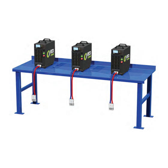
Location The preferred installation is where the charger(s) can be located on a shelf, protected against accidental contact with the lift truck or its forks. With the charger on a shelf the risk of damage to the charger or battery cables is greatly reduced. -
Page 5: Mounting Bracket Options
2. Remove the 2x front case feet. 3. Slide the base of the FS3 onto the mounting bracket. 4. With 2x M5x8 hex bolts (included with the mounting bracket) secure the front of the mounting bracket to the FS3. -
Page 6: Installation
Installation AC Input & Busbar Connection AC Supply Charger Charger Supply Supply in Max. Aux. Busbar Config. Model Modules Phase Output Voltage Amps. Plug Selection Number Number Per Phase FS3LUE- Single 24/36/ 208- MP130 Phase FS3LUE- Three 24/36/ 208- 15.5- MP130 Phase 23.2**... - Page 7 AC Filter Board Configuration - Step 1 of 3 AC Input STEP Terminal Block Note: Terminal connections to be tightened to 21 in.lbs Configuration 1 - MP130 Configuration 2 - MP130 208-240V AC Single Phase. 208-240V AC Single Phase Split Leg. 208-240 208-240V AC 208-240V AC...
- Page 8 Use an 8mm socket on the M5 hex head bolts to secure the busbars in place. Unused busbar connections are bolted to the internal rear of the FS3 cabinet. AC Filter Board Configuration - Step 3 of 3...
-
Page 9: Fs3 Block Diagram
FS3 Block Diagram FS3 Block Diagram .9... -
Page 10: Operating Instructions
Operating Instructions Check the battery leads are in good condition before proceeding. Set the rocker switch to STOP. Plug the charger in and turn on the AC supply. Check the voltage, amphr and battery type indicated on the charger’s display matches the battery to be charged. Connect the battery to the charger using the correct cable. - Page 11 Operating Instructions .11...
-
Page 12: Front Panel (Set Equalize Charge)
Front Panel Controller display. Displays information depending on the status of the charger. Controller push buttons (Set Equalize Charge). To enable equalize next cycle, plug in the battery but before setting the rocker switch to START: - Press button to set equalize next cycle. - Press ENTER to allow changing. - Page 13 RED LED same as RED indicator. button. AMBER LED same ENTER as GREEN indicator. button. GREEN LED DOWN illuminates when button. charger is powered up. Display when no battery Display when Display when charge connected or rocker charging. complete. switch set to STOP. Rolling Rolling Charging...
-
Page 14: Charger Configuration Settings
Charger Configuration Settings Charge Profiles Available Day/time: Conventional IUIa/IEI. Select day and time of the week to Opportunity charge. trigger an equalize charge on the next charge cycle. Can also select Amp Hr Ranges to have it equalize charge every Conventional profile: other week. -
Page 15: Charger Alarms
Charger Alarms Main Switch Non-Urgent Module Fail Configuration Error APC Communications Fail Inlet Filter Urgent Module Fail Output Fuse APC Incorrect Voltage Low Mains Module Fan Fail No Output Current APC Unknown Charger Mains Fail Module Over Temperature Monitor ADC Fail Charger Alarms Main Switch. - Page 16 Charger Alarms Module Over Temperature. Urgent Alarm, normally related to a blocked filter or restricted exhaust air or installation in an inappropriate location. Configuration Error. Urgent Alarm, the charger cannot meet the target current required by the controller even with all fitted charger modules operating or the configuration does not meet the limits set for a 10A mains input hardware limited charger.
-
Page 17: Battery Alarms
Battery Alarms Over Discharged Battery Bulk Charge Timeout Minimum dV/dt +dI/dt Deeply Discharged Battery Finishing Charge Timeout Maximum Cell Voltage Minimum Current Sulphated Battery Battery Disconnected Batt Over Temp - Start EQ/Refresh Timeout Incorrect Battery Reversed Battery Batt Over Temp - Charge Battery Alarms Over Discharged Battery. - Page 18 Battery Alarms Finishing Charge Timeout. Non-Urgent Alarm, the battery has exceeded the maximum time allowed for the finishing part of the charge cycle. Generally not a major problem and indicates the battery did not quite perform as expected. Not uncommon with new batteries that are still cycling up to full capacity (allow 10 cycles) however if the alarm is a regular occurrence it needs investigation and possible adjustment of the charger or service of the battery.
- Page 19 Maximum Cell Voltage. Non-Urgent Alarm, occurs when the voltage per cell exceeds the value set in the profile settings. Typically 2.7V per cell for lead acid batteries. Batt Over Temp - Start. Urgent Alarm, occurs when the battery temperature measured before a charge profile starts exceeds the value set in the controller settings.
-
Page 20: Troubleshooting
Troubleshooting Problem Possible Cause Remedy Front panel switch in Charge will start when the Main Switch Alarm. the STOP position. switch is set to START. Inlet Filter Alarm. Air inlet filter blocked. Clean the filter. AC mains supply is Check configuration of the Low Mains Alarm. - Page 21 Problem Possible Cause Remedy Typically due to the battery being quickly unplugged from Battery is <1.9Vpc the truck and plugged onto Over Discharged at connection but the charger without allowing Battery. recovers within 30 the battery to recover. Regular seconds of charge. occurrences might need investigation of work practices.
-
Page 22: Exploded View
Exploded View 22. Exploded View... -
Page 23: Spare Parts
MP330 Module 3 Across Backplane Assembly SM31 Large Display Assembly Voltage Sensor MPC35 Main Board Assembly FS3 AC Filter and Voltage Selection Assembly Stud Diode 150A 300V Fuse HRC180A 150VDC 240VAC Front Control Panel Membrane USB Hole Plug Carry Handle... - Page 24 Spare Parts Image Description Mounting Bracket Case Foot FS3 Cabinet FS3 Lid FS3 Side Panel DC Output Loom Blanking Plate Oval Blanking Plate Conduit Welded Filter Assembly Front Panel Green Indicator Front Panel Red Indicator Front Panel Rocker Switch 24. Spare Parts...
-
Page 25: Maintenance
Maintenance Provided it is correctly installed in an appropriate location and is not abused, the charger will require little maintenance. The only requirement is to monitor the air inlet filter at the front of the charger for dirt accumulation. The charger modules internal to the charger housing require a good supply of cooling air during the charge cycle and a blocked filter will affect the cooling. -
Page 26: Service & Warranty
Service & Warranty Service If both the RED and GREEN indicators are flashing there has been an Urgent Alarm that has prevented the charge cycle from completing. Take note of the error displayed on the display and contact your servicing battery dealer or call DC Power Technolgoies (DCPT) at 1-844-ECO-CHRG for assistance. -
Page 28: Specifications
Specifications FS3 Cabinet Dimensions (in): 7.75W x 15.25D x 15.25H Weight: 46 pounds (with 3 modules) MP130 & MP330 Modules AC Input MP130 MP330 Single phase 208/240V Three phase 480V Three phase 208/240V Nominal Input Voltage: 208-278V AC 380-480V AC...
Need help?
Do you have a question about the FS3 and is the answer not in the manual?
Questions and answers