Table of Contents
Advertisement
Advertisement
Table of Contents

Related Manuals for Viking VCCU105-4B


Summary of Contents for Viking VCCU105-4B
- Page 1 SERVICE NOTEBOOK VCCU105-4B / VCCU165-6B / VICU105-4B / VICU165-6B...
- Page 2 SERVICE NOTEBOOK VCCU105-4B / VCCU165-6B / VICU105-4B / VICU165-6B...
-
Page 3: Table Of Contents
Induction/Radiant Power Board Recognition-------------------------------------------- Induction/Radiant Ribbon Connection Designations----------------------------------- Induction/Radiant LED Indicator Replacement Description-------------------------- Wiring Diagrams 30” W. Induction/Radiant Cooktop----------------------------------------------- 36” W. Induction/Radiant Cooktop----------------------------------------------- Block Diagrams 30” All Induction Cooktop--------------------------------------------------------- 36” All Induction Cooktop--------------------------------------------------------- Block Diagram Viking 30” / 36” Mixed Fuel Cook-Top------------------------------------------... -
Page 4: Basic Specifications Induction/Radiant Cooktops
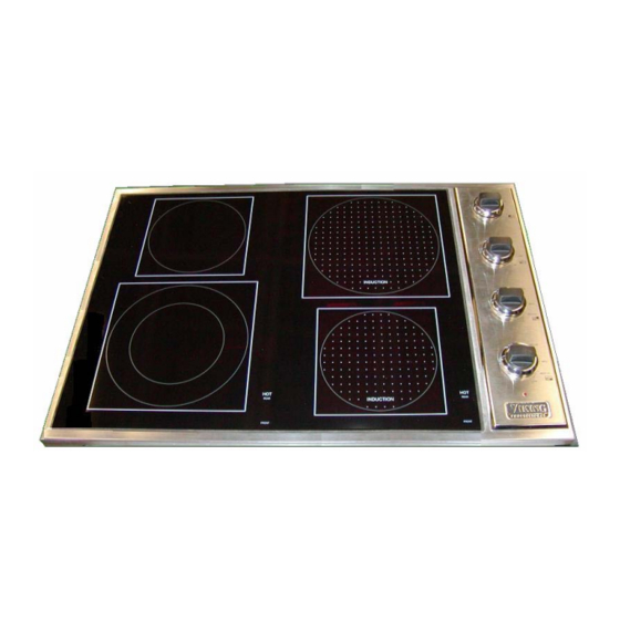
Viking induction cooktops are available as all-induction or induction / radiant models, which feature Quick-Cook™ electric surface elements in addition to induction power generators. And the standard 30” and 36” wide sizes fit easily into your existing counter space. -
Page 5: Proximity To Side Cabinets
INSTALLLATION PROXIMITY TO SIDE CABINET IMPORTANT: The electronic components for the induction elements in the cooktop need some air circulation. To ensure long life of electronic components, it is required that a minimal amount of open space remain between the bottom of the cooktop and any shelf underneath. -
Page 6: Dimensions - Induction/Radiant 30" Cooktop
INSTALLATION (continued) Dimensions – Induction / Radiant Cooktop – 30” After installation of cooktop, locate the four hold down brackets on each side of the burner box. Screw the sheet metal screw into bracket and tighten firmly against bottom of countertop. Dimensions –... -
Page 7: Dimensions - All Induction 30" Cooktop
INSTALLATION (continued) Dimensions – All Induction Cooktop 30” After installation of cooktop, locate the four hold down brackets on each side of the burner box. Screw the sheet metal screw into bracket and tighten firmly against bottom of countertop. Dimensions – All Induction cooktop 36” After installation of cooktop, locate the four hold down brackets on each side of the burner box. -
Page 8: Cooking Utensils
Cooking Utensils for Radiant Elements Each cook has his or her own preference for the particular cooking utensils that are most appropriate for the type of cooking being done. Only certain types of glass, glass/ceramic, ceramic, earthware, or other glazed utensils are suitable for glass cooktop use without breaking due to the sudden change in temperature. - Page 9 Surface Cooking Operating the Single Front or Rear Element Push in an turn the corresponding control knob counterclockwise to the desired setting. The element will cycle on and off to maintain the desired heat setting. When finished, turn all controls OFF. Operating the Rear and Bridge Element Push in and turn the corresponding control knob clock wise to desired setting.
-
Page 11: Caution - High Voltage
DISASSEMBLE FOR SERVICE... -
Page 12: Vccu105-4B
VCC105-4B To gain access to service or replace the components remove the glass top. There are two screws (A) on each side of the cooktop. To prevent disconnecting the component wiring lift up the glass top at the end away from the control panel. -
Page 13: Vccu165-6B
VCCU165-6B To gain access to service or replace the components remove the glass top. There are three screws (B) on each side of the cooktop. To prevent disconnecting the component wiring, lift up the glass top at the end away from the control panel. -
Page 14: Vicu105-4B
VICU105-4B To gain access to service or replace the components remove the glass top. There are two screws (A) on each side of the cooktop. Thermistors To prevent disconnecting the component wiring, lift up the glass top at the end away from the control panel. -
Page 15: Vicu165-6B
VICU165-6B To gain access to service or replace the components remove the glass top. There are three screws (A) on each side of the cooktop. Thermistors To prevent disconnecting the component wiring, lift up the glass top at the end opposite the control panel. -
Page 16: Induction/Radiant Cooktop Power & Emi Board Layout
INDUCTION / RADIANT COOKTOP POWER & EMI BOARD... -
Page 17: All Induction Cooktop Power Board Layout
ALL INDUCTION POWER BOARD... -
Page 18: Induction/Radiant Power Line Connector & Emi Board Layout
EMI BOARD POWER LINE CONNECTOR... -
Page 19: All Induction Vicu165-6B Power & Emi Board Layout
VICU165-6B ALL INDUCTION POWER AND EMI BOARDS... -
Page 20: Induction/Radiant Coil Tray Removal
COIL TRAY REMOVAL STEP 1 Disconnect thermistor cables as shown in the figure below. - Page 21 COIL TRAY REMOVAL STEP 2 Unscrew coil wires. CAUTION: BE CAREFUL TO CAPTURE THE SCREW AND LOCKWASHER, DO NOT LET THEM FALL INTO THE UNIT, AS THEY COULD CAUSE A SHORT LATER. The coil wire for the front coil connects to the TP4 (L) on the left.
-
Page 22: Induction/Radiant Power Board Recognition
POWER BOARD RECOGINITION The HPS (TP3) high voltage board is easily identified by the fact that the two capacitors run in a parallel direction to the small heat-sink device. Conversely, on the LPS (TP4) low voltage board the two capacitors run perpendicular to the small heat-sink device. Front coil is operated by the LPS (TP4) board. -
Page 23: Induction/Radiant Ribbon Connection Designations
RIBBON CONNECTOR DESIGNATIONS The longer of the two cables from the LPS plugs into the 14-pin connector with the designator JF. The shorter of the two cables from the HPS plugs into the 14-pin connector with the designator JR POTENTIOMETER CABLE DESIGNATIONS Potentiometer wires are plugged into the male quick-disconnects located on the EMI board and clearly marked as shown in the figure below left. -
Page 24: Induction/Radiant Led Indicator Replacement Description
LED INDICATOR REPLACEMENT DESIGNATION Detail showing wire soldered to the PCB that supports the two LEDs. PBC is tied to and L-bracket mounted to the front of the cooktop. The opposite wire ends connect to the male quick-disconnects located and clearly identified on the EMI board. Because LEDs have polarity, the RED and BLACK wire MUST be placed in their appropriate slots. -
Page 25: Wiring Diagrams
WIRING DIAGRAM 30” W. INDUCTION/RADIANT COOKTOP... -
Page 26: 36" W. Induction/Radiant Cooktop
WIRING DIAGRAM 36” W. INDUCTION/RADIANT COOKTOP... -
Page 27: 30" All Induction Cooktop
WIRING DIAGRAM 30” W. ALL INDUCTRION COOKTOP... -
Page 28: 36" All Induction Cooktop
WIRING DIAGRAM 36” W. ALL INDUCTION COOKTOP...
Need help?
Do you have a question about the VCCU105-4B and is the answer not in the manual?
Questions and answers