Table of Contents
Advertisement
Advertisement
Table of Contents

Related Manuals for Prowill is900

Summary of Contents for Prowill is900
- Page 1 User Manual...
- Page 3 Notice Make sure you carefully read the following information to ensure that your barcode scanner is able to perform at the level for which it is designed. All software, including firmware, furnished to the user is on a licensed basis. The right is reserved to make changes to any software or product to improve reliability, function, or design.
- Page 4 a higher location, generally more than 1 meter above the ground. If working outdoor, the higher location the better.
-
Page 5: Safety Precautions - Danger
Safety precautions – Danger! Be sure to read the following safety precautions carefully before trying to use the barcode scanner for the first time. Keep this manual in handy place for future reference. Danger! This symbol indicates information that, if ignored or applied incorrectly, creates the danger of death or serious personal injury. -
Page 6: Safety Precautions - Warning
Safety precautions – Warning! Warning! This symbol indicates information that, if ignored or applied incorrectly, can create the possibility of death or serious personal injury. Disassembly and modification Never try to disassemble or modify the unit in any way. High voltage inside creates the danger of electrical shock. - Page 7 Cradle with RS-232 cable and adaptor Power the cradle only with a power outlet whose voltage matches that marked on the adaptor specified in this manual. Avoid conditions that can cause damage or breaks in the power cord. Do not place heavy objects on the power cord.
-
Page 8: Safety Precautions - Caution
Safety precautions – Caution! Caution! This symbol indicates information that, if ignored or applied incorrectly, can create the possibility of personal injury or material damage. Foreign objects Take care to ensure that metal or combustible objects are not inserted into the openings of the unit. Such objects create the danger of fire and electrical shock. - Page 9 insulation of the power cord and create the danger of fire and electrical shock. Never pull on the power cord when unplugging it. Doing so can damage the cord and create the danger of personal injury, fire and electrical shock. Always hold onto the pug when unplugging it from the wall outlet.
- Page 10 viii...
-
Page 11: Table Of Contents
Contents Notice..............................i Safety precautions – Danger!......................iii Safety precautions – Warning! ......................iv Safety precautions – Caution! ......................vi Technical specifications ........................1 Cable connector pin-outs descriptions for cradle................3 Default setting for each barcode......................4 Decode zone............................5 Dimensions ............................6 Parts of the scanner .......................... - Page 12 Industrial 2 of 5........................... 49 Matrix 2 of 5 ............................50 Codabar............................... 51 Code 128............................. 52 UCC/EAN 128 ............................ 53 ISBT 128 ............................. 54 Code 93 ............................... 55 Code 11 ............................... 56 MSI/Plessey ............................57 UK/Plessey............................58 China Post............................59 GS1 DataBar (GS1 DataBar Truncated) ..................
-
Page 13: Technical Specifications
Technical specifications Handheld unit Dimensions Length × Width × Depth: 17.0 × 7.0 × 8.3 cm Weight 201 g Color Gray 1400 mAh Lithium-ion battery Battery Charge time Fully charged (>80%) in 3.5 hours Case material Fire-retardant ABS+TPU Light source 650 nm visible laser diode Decoding rate 200 times/sec... - Page 14 Test condition: temperature at 27 ° C, sunny day, and visibility of 5 kilometers. Natural Note: surroundings significantly affect the communication distance in practice. The distance drops quickly in the rainy, high-humidity, or heavy haze day; radio interference also shortens the communication distance.
-
Page 15: Cable Connector Pin-Outs Descriptions For Cradle
Cable connector pin-outs descriptions for cradle Cable connector interface pin-outs The pin-outs descriptions in Table 1 apply to the cable connector on the cradle and are for reference only. Table 1-1 Cable connector pin-outs descriptions RS232 Keyboard (PS2) Power (+5V) Power (+5V) +3.3V ( for interface auto Ground (for interface auto... -
Page 16: Default Setting For Each Barcode
Default setting for each barcode Read Check digit Check digit Min. code Proprietary Code type enable verification transmission length code ID code ID UPC-A √ √ √ (12) UPC-E √ √ √ UPC-E1 √ √ √ EAN-13 √ √ √ (13) EAN-8 √... -
Page 17: Decode Zone
Decode zone High-density series Long-range series... -
Page 18: Dimensions
Dimensions... -
Page 19: Parts Of The Scanner
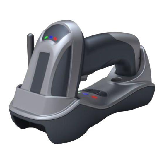
Parts of the scanner Handheld unit ① Exit window ② Trigger ③ Red LED (Charging indicator) ④ Communication/Charge socket ⑤ Power button ⑥ Sound hole ⑦ Red LED (Not successful transmission); Blue LED (Power); Green LED (Setting) Cradle ① B button (Reserved); S button (Upgrade / Reset); P button (USB Emulate) ②... -
Page 20: Power On, Power Off Handheld Unit And Charge Battery
Power on, power off handheld unit and charge battery Power on handheld unit: Press the power button for two seconds. (see Parts of the scanner) Power off handheld unit: Press the power button for two seconds. (see Parts of the scanner) Charge battery: 1. -
Page 21: Installation Of Cradle
Installation of cradle Note: If any of the below operation is incorrect, turn off the power immediately and check the scanner for any improper connections. Go through all steps again. With PS2 cable Plug one end of the PS2 cable to the cradle, one end to PS2 port on PC, and one end to the keyboard. - Page 22 With RS-232 cable Connect the DB9 serial communication cable with the cradle and the COM port of the computer. Plug the output of the AC/DC adaptor into the power terminal of on the cradle. Plug the AC/DC adaptor provided by the manufacturer into an electrical outlet.
-
Page 23: Programming Instruction
Programming instruction The steps of programming are: 1. Scan the SETUP bar code on the parameter setting part. 2. Enter the option mode by scanning the Option bar code. 3. To the right of the option barcode, the necessary alphanumeric inputs are listed. Scan these alphanumeric entries from the back foldout page. -
Page 24: Description Of Point Coordination And Distributed Coordination Wireless Network
Description of point coordination and distributed coordination wireless network Notes: 1. In this section, “cluster” denotes an association of a cradle and a number of handheld units. 2. In this section, “RF” is the abbreviation for “radio frequency”. The scanner offers two kinds of wireless network topology: point coordination and distributed coordination. -
Page 25: Sketch Map Of Distributed Coordination Operating Mode
Cluster 1 Cluster 2 2. Sketch map of distributed coordination operating mode This series of cordless barcode scanner is working at 430MHz ~432MHz, 433.05MHz~434.79MHz and is covered by a patent of wireless communication method named LR-433-WPAN wireless communication protocol. Single cluster - single handheld unit Single cluster –... -
Page 26: Point Coordination Wireless Communication Setting
Point coordination wireless communication setting 1. Point coordination wireless communication setting for handheld unit Wireless network topology for handheld unit: There are two kinds of wireless network topology that can be employed: point coordination and distributed coordination. Handheld unit RF channel No.: The scanner offers 16 different radio frequency channels for the data transmission between handheld unit and cradle. - Page 27 5 times, and the beeper emits 5 beepers for every 10 minutes or 200 scans. In this battery low status, the power LED flashes 2 times by pulling the scanner trigger. Enter sleeping mode interval: If it is enabled, the handheld unit will enter sleeping mode while no operation beyond the time interval defined;...
- Page 28 from PC. Command packet Operations of base unit / cradle LED indication Red LED flashes once, VALID Send VALID command packet to the handheld unit. green LED on. Red LED flashes once, INVALID Send INVALID command packet to the handheld unit. green LED off.
- Page 29 SETUP Option barcode Option Alpha. entry Point coordination Wireless network topology for handheld unit Distributed coordination 02-16 02-16 Handheld unit RF channel No. 01-16 01-16 Handheld unit ID 10dbm 7dbm 5dbm Radio power level for handheld unit 0dbm -5dbm -10dbm -15dbm Disable Frequency hopping...
- Page 30 Note: The settings indicated with (※) are valid only when the cradle is in upgrade ready mode. Cradle entering upgrade ready mode Keep pressing the S button on the cradle, until the blue LED is flashing. Then three LEDs will all be turned ON, this indicates the cradle being upgrade ready mode.
-
Page 31: Point Coordination Wireless Communication Setting For Cradle
2. Point coordination wireless communication setting for cradle Wireless network topology for cradle: There are two kinds of wireless network topology that can be employed: point coordination and distributed coordination. Cradle RF channel No.: The scanner offers 16 different radio frequency channels for the data transmission between handheld unit and cradle. - Page 32 SETUP Option barcode Option Alpha. entry Point coordination Wireless network topology for cradle ※ Distributed coordination 02-16 Cradle RF channel No. ※ 02-16 01-16 Bind the first handheld unit ID ※ 01-16 Recruit a next handheld unit ID ※ 01-16 01-16 10dbm 7dbm...
-
Page 33: Distributed Coordination Wireless Communication Setting
Distributed coordination wireless communication setting 1. Cluster establishment example 1.0 The flow chart of the general architecture of establishing a cluster is shown below. 1.1 Establish the wireless link between the cradle and the first handheld unit. Step 1.0 Please refer to chapter “return default parameters & version chapter” to check the current wireless network topology. - Page 34 The blue LED on the handheld will blink to indicate that the handheld unit is ready to be positioned onto the cradle. Scan BIND barcode to pair the handheld unit and the cradle. The handheld unit is dedicated to the cradle. Any previous bound handheld units will be excluded.
-
Page 35: Distributed Coordination Wireless Communication Setting For Handheld Unit
2. Distributed coordination wireless communication setting for handheld unit Wireless network topology for handheld unit: There are two kinds of wireless network topology that can be employed: point coordination and distributed coordination. Handheld unit RF channel No.: The scanner offers 16 different radio frequency channels for the data transmission between handheld unit and cradle. - Page 36 SETUP Option barcode Options Value Point coordination Wireless network topology for handheld unit Distributed coordination 02-16 02-16 Handheld unit RF channel No. 0000-1999 Handheld unit address 0000-1999 0000* 10dbm 7dbm 5dbm Radio power level for handheld unit 0dbm -5dbm -10dbm -15dbm 02-20 Interval for radio communication...
-
Page 37: Distributed Coordination Wireless Communication Setting For Cradle
3. Distributed coordination wireless communication setting for cradle Wireless network topology for cradle: There are two kinds of wireless network topology that can be employed: point coordination and distributed coordination. Radio power level for cradle: By selecting, you can change the radio frequency power level for cradle. SETUP Option barcode Options... -
Page 38: Scanning
Scanning When the scanner is scanning, ensure the scan line crosses every bar and space of the symbol. RIGHT WRONG... -
Page 39: Keyboard Wedge Interface For Cradle
Keyboard wedge interface for Cradle Keyboard type: As a keyboard interface, the scanner supports most of the popular PCs and IBM terminals. Keyboard layout: The scanner supports different national keyboard layouts. Clock period: According to the PS2 protocol, the clock is provided by the device, e.g. keyboard or scanner, with the period between 60us to 100us. - Page 40 SETUP Option bar code Option Alpha. entry IBM AT, PS/2 Keyboard type Apple Mac compatibles Reserved Turkish F Turkish Q French Italian Keyboard layout Spanish Slovak Denmark Japanese German Belgian Russian 60us 70us Clock period 80us 90us 100us 200us 10ms Delay-after-compound-key 20ms 40ms...
- Page 41 SETUP Option bar code Option Alpha. entry Caps Lock override Disable Enable...
-
Page 42: Rs-232 Interface For Cradle
RS-232 interface for Cradle Flow control: None-The communication only uses TxD and RxD signals without any hardware or software handshaking protocol. RTS/CTS-If the scanner wants to send the barcode data to host computer, it will issue the RTS signal first, wait for the CTS signal from the host computer, and then perform the normal data communication. If there is no replied CTS signal from the host computer after the timeout duration, the scanner will issue an error indication. - Page 43 SETUP Option bar code Option Alpha. entry None Flow control RTS/CTS (Host idle: Low RTS) RTS/CTS (Host idle: High RTS) XON/XOFF ACK/NAK Inter-character delay 10ms 20ms 40ms 80ms Reserved Response delay 00-99 (100ms) 00-99 1200 2400 Baud rate 4800 9600 19200 38400 57600...
-
Page 44: Usb Interface For Cradle
USB interface for Cradle USB device type: When the cradle is connected to a PC with a USB cable, it will be identified as a HID keyboard. HID keyboard– By setting, the scanner is used as a USB HID keyboard emulation device. keyboard layout setting follows the setting of keyboard layout in the chapter of Keyboard wedge. - Page 45 SETUP Option bar code Option Alpha. entry HID keyboard USB device type HID keyboard for Apple Mac USB virtual COM Simple COM Port Emulation Turkish F Turkish Q French Italian Keyboard layout Spanish Slovak Denmark Japanese German Belgian Russian Host comm. port speed 00-08 (0: highest;...
-
Page 46: Handheld Scan & Some Global Settings
Handheld scan & some global settings Scanning mode: Good-read off-The trigger button must be pressed once to activate scanning. The light source of scanner stops scanning when there is a successful reading or no code is decoded after the Stand-by duration elapsed. - Page 47 Decoder optimization: If it is enabled, the scanner will optimize the decoder with error correction. This function is not effective for all types of barcodes. SETUP Option bar code Option Alpha. entry Good-read off Momentary Scanning mode Alternate Continue Timeout off Standby duration 01-99 (second) 01-99...
-
Page 48: Visual And Audio Indication For Handheld Unit
Visual and audio indication for handheld unit Power on alert: After power-on the scanner will generate an alert signal to indicate a successful self-test. LED indication: After each successful reading, the LED above the scanner will light up to indicate a good barcode reading. -
Page 49: Upc-A
UPC-A Read: Format System character Data digits (10 digits) Check digit Check digit verification: The check digit verification is optional. Check digit trans.: By setting Enable, check digit will be transmitted. Code ID setting: Code ID is a one-or-two-character string used to represent the symbol upon a succeeding reading. - Page 50 SETUP Option bar code Option Alpha. entry Read Disable Enable Check digit verification Disable Enable Check digit trans. Disable Enable Code ID setting 00-FF 00-FF (ASCII) <A>* Insert group selection 00-66 00-66 None Supplement digits 2 digits 5 digits 2 or 5 digits None Truncate leading zeros Truncation/Expansion...
-
Page 51: Upc-E
UPC-E Read: Format System character “0” Data digits (6 digits) Check digits Check digit verification: The check digit verification is optional and made as the sum of the numerical value of the data digits. Check digit trans.: By setting Enable, check digit will be transmitted. Code ID setting: Refer to Code ID setting of UPC-A. - Page 52 SETUP Option bar code Option Alpha. entry Read Disable Enable Check digit verification Disable Enable Check digit trans. Disable Enable Code ID setting 00-FF 00-FF (ASCII) <D>* Insert group selection 00-66 00-66 None Supplement digits 2 digits 5 digits 2 or 5 digits None Truncation/Expansion Truncate leading zeros...
-
Page 53: Upc-E1
UPC-E1 Read: Format System character “1” Data digits (6 digits) Check digits Check digit verification: The check digit is optional and made as the sum of the numerical value of the data digits. Check digit trans.: By setting Enable, check digit will be transmitted. Code ID setting: Refer to Code ID setting of UPC-A. - Page 54 SETUP Option bar code Option Alpha. entry Read Disable Enable Check digit verification Disable Enable Check digit trans. Disable Enable Code ID setting 00-FF 00-FF (ASCII) <D>* Insert group selection 00-66 00-66 None Supplement digits 2 digits 5 digits 2 or 5 digits None Truncation/Expansion Reserved...
-
Page 55: Ean-13 (Isbn/Issn)
EAN-13 (ISBN/ISSN) Read: Format Data digits (12 digits) Check digit Check digit verification: The check digit is optional and made as the sum of the numerical value of the data digits. Check digit transmission: By setting Enable, check digit will be transmitted. EAN-13 code ID setting: Refer to Code ID setting of UPC-A. - Page 56 SETUP Option bar code Option Alpha. entry Read Disable Enable Check digit verification Disable Enable Check digit transmission Disable Enable EAN-13 code ID setting 00-FF 00-FF (ASCII) <A>* Insert group selection 00-66 00-66 None Supplement digits 2 digits 5 digits 2 or 5 digits ISBN/ISSN conversion Disable...
-
Page 57: Ean-8
EAN-8 Read: Format Data digits (7 digits) Check digit Check digit verification: The check digit is optional and made as the sum of the numerical value of the data digits. Check digit trans.: By setting Enable, check digit will be transmitted. Code ID setting: Refer to Code ID setting of UPC-A. -
Page 58: Code 39 (Code 32, Trioptic Code 39)
Code 39 (Code 32, Trioptic Code 39) Read: Format ⋆ Data digits (variable) Check digit (optional) ⋆ Check digit verification: The check digit is optional and made as the sum module 43 of the numerical value of the data digits. Check digit transmission: By setting Enable, check digit will be transmitted. - Page 59 SETUP Option bar code Option Alpha. entry Read Disable Enable Check digit verification Disable Enable Check digit transmission Disable Enable Max. code length 00-99 00-99 Min. code length 00-99 00-99 Code ID setting 00-FF 00-FF (ASCII) <M>* Insert group selection 00-66 00-66 Format...
-
Page 60: Interleaved 2 Of 5
Interleaved 2 of 5 Read: Format Data digits (Variable) Check digit (optional) Check digit verification: The check digit is made as the sum module 10 of the numerical values of all data digits. There are two optional check digit algorithms: the specified Uniform Symbol Specification (USS) and the Optical Product Code Council (OPCC). -
Page 61: Industrial 2 Of 5
Industrial 2 of 5 Read: Format Data digits (variable) Max./Min. code length: Refer to Max./Min. code length of Code 39. Code ID setting: Refer to Code ID setting of UPC-A. Insertion group selection: Refer to Insertion group selection of UPC-A. SETUP Option bar code Option... -
Page 62: Matrix 2 Of 5
Matrix 2 of 5 Read: Format Data digits (variable) Check digit (optional) Check digit verification: The check digit is made as the sum module 10 of the numerical values of all data digits. Check digit transmission: By setting Enable, check digit will be transmitted. Max./Min. -
Page 63: Codabar
Codabar Read: Format Start Data digits (variable) Check digit (optional) Check digit verification: The check digit is made as the sum module 16 of the numerical values of all data digits. Check digit transmission: By setting Enable, check digit will be transmitted. Max./Min. -
Page 64: Code 128
Code 128 Read: Format Data digits (variable) Check digit (optional) Check digit verification: The check digit is made as the sum module 103 of all data digits. Check digit transmission: By setting Enable, check digit will be transmitted. Max./Min. code length: Refer to Max./Min. code length of Code 39. Code ID setting: Refer to Code ID setting of UPC-A. -
Page 65: Ucc/Ean 128
UCC/EAN 128 Read: Format Data digits (variable) Check digit (optional) Check digit verification: The check digit is made as the sum module 103 of all data digits. Check digit transmission: By setting Enable, check digit will be transmitted. Max. /Min. code length: Refer to Max./Min. code length of Code 39. Code ID setting: Refer to Code ID setting of UPC-A. -
Page 66: Isbt 128
ISBT 128 Read: Format “=” or “&” Data digits (variable) Check digit (optional) Check digit verification: The check digit is made as the sum module 103 of all data digits. Check digit transmission: By setting Enable, check digit will be transmitted. Max./Min. -
Page 67: Code 93
Code 93 Read: Format Data digits (variable) 2 check digits (optional) Check digit verification: The check digit is made as the sum module 47 of the numerical values of all data digits. Check digit transmission: By setting Enable, check digit will be transmitted. Max./Min. -
Page 68: Code 11
Code 11 Read: Format Data digits (variable) Check digit 1 (optional ) Check digit 2 (optional) Check digit verification: The check digit is presented as the sum module 11 of all data digits. Check digit transmission: By setting Enable, check digit 1 and check digit 2 will be transmitted upon your selected check digit verification method. -
Page 69: Msi/Plessey
MSI/Plessey Read: Format Data digits (variable) Check digit 1 (optional) Check digit 2 (optional) Check digit verification: The MSI/Plessey has one or two optional check digits. There are three methods of verifying check digits, i.e. Mod10, Mod10/10 and Mod 11/10. The check digit 1 and check digit 2 will be calculated as the sum module 10 or 11 of the data digits. -
Page 70: Uk/Plessey
UK/Plessey Read: Format Data digits (variable) 2 check digits (optional) Check digit verification: The UK/Plessey has one or two optional check digits. The check digit 1 and check digit 2 will be calculated as the sum module 10 or 11 of the data digits. Check digit transmission: By setting Enable, check digit will be transmitted. -
Page 71: China Post
China Post Read: Format 11 Data digits Max. /Min. code length: Refer to Max./Min. code length of Code 39. The code length of China Post is Code ID setting: Refer to Code ID setting of UPC-A. Insertion group selection: Refer to Insertion group selection of UPC-A. SETUP Option bar code Option... -
Page 72: Gs1 Databar (Gs1 Databar Truncated)
GS1 DataBar (GS1 DataBar Truncated) GS1 DataBar Truncated is structured and encoded the same as the standard GS1 DataBar format, except its height is reduced to a 13 modules minimum; while GS1 DataBar should have a height greater than or equal to 33 modules. Read: Format 16 Data digits... -
Page 73: Gs1 Databar Limited
GS1 DataBar Limited Read: Format 16 Data digits Code ID setting: Refer to Code ID setting of UPC-A. Insertion group selection: Refer to Insertion group selection of UPC-A. Conversion: Refer to Conversion of GS1 DataBar (GS1 DataBar Truncated). SETUP Option bar code Option Alpha. -
Page 74: Gs1 Databar Expanded
GS1 DataBar Expanded Read: Format Data characters (variable) Code ID setting: Refer to Code ID setting of UPC-A. Insertion group selection: Refer to Insertion group selection of UPC-A. Conversion: UCC/EAN 128- Refer to Code ID transmission of String transmission, ]Cm will be identified as AIM ID. SETUP Option bar code Option... -
Page 75: China Finance
China Finance Note: This type of barcode is not Omni-directionally decodable. The encodable character set includes numeric 0 to 9. Among the symbol of 0 to 9, 0 and 2, 4 and 9, 5 and 8, 6 and 7, have the symmetrical pattern;... - Page 76 SETUP Option bar code Option Alpha. entry Read Disable Enable Max. code length 00-99 00-99 Min. code length 00-99 00-99 Check digit verification Disable Reserved Disable Enable Leading character 5/6/7/8/9 Only 5 converted to A converted to A/B/C/D/E Only 6 converted to B Only 7 converted to C Only 8 converted to D Only 9 converted to E...
-
Page 77: G1-G6 & Fn1 Substitution String Setting
G1-G6 & FN1 substitution string setting Format of barcode data transmission Prefix Code name Preamble Code ID Code length Code data Code ID Postamble Suffix Suffix string setting: The <enter > key is represented in different ASCII when it is applied by different OS. For a Windows/DOS OS, <enter>... - Page 78 FN1 substitution string setting: The FN1 character (0x1D) in an UCC/EAN128 barcode, or a Code 128 barcode, or a GS1 DataBar barcode can be substituted with a defined string. Truncate leading G5 string setting: By setting, a defined leading character or string can be truncated. Also a single character can be un-defined.
- Page 79 SETUP Option bar code Option Alpha. entry Prefix string setting 0-22 characters 00-FF None Suffix string setting 0-22 characters 00-FF <ENTER> 0D0A* Preamble string setting 0-22 characters 00-FF None Postamble string setting 0-22 characters 00-FF None Insert G1 string setting 0-22 characters 00-FF None...
-
Page 80: G1-G4 String Position & Code Id Position
G1-G4 string position & Code ID position Format of barcode data transmission Prefix Code name Preamble Code ID Code length Code data Code ID Postamble Suffix Insert G1/G2/G3/G4 string position: The scanner offers 4 positions to insert strings among the symbol. In case of the insertion position is greater than the length of the symbol, the insertion of string is not effective. -
Page 81: String Transmission
String transmission Note: The information in this chapter is closely related to the chapter of String setting. Format of barcode data transmission Prefix Code name Preamble Code ID Code length Code data Code ID Postamble Suffix Prefix transmission: By setting Enable, prefix will be appended before the data transmitted. Suffix transmission: By setting Enable, suffix will be appended after the data is transmitted. - Page 82 SETUP Option bar code Option Alpha. entry Prefix transmission Disable Enable Suffix transmission Disable Enable Code name transmission Disable Enable Preamble transmission Disable Enable Postamble transmission Disable Enable Disable Code ID transmission Proprietary ID AIM ID Code length transmission Disable Enable Disable Upper (data only)
-
Page 83: Test Chart
Test Chart UPC-A UPC-E EAN-8 EAN-13 Code 39 Code 32 A908765439 Code 128 Interleaved 2 of 5 Industrial 2 of 5 (Default setting: Read disable) Matrix 2 of 5 Code 93 UCC/EAN 128 Code 11 (Default setting: Read disable) -
Page 84: Test Chart (Continued)
Test Chart (Continued) MSI/Plessey (Default setting: Read disable) UK/Plessey ISBN/ISSN China Post GS1 DataBar (GS1 DataBar Truncated) GS1 DataBar Limited GS1 DataBar Expanded... -
Page 85: Troubleshooting
Troubleshooting Problem Possible causes Possible solutions Nothing happens when you No power to the Check the system power. Ensure the power follow the operating scanner. supply is connected. instructions, or the scanner Incorrect cables. Use the original cables. displays erratic behavior. Connections are Check for loose cable connections. -
Page 86: Maintenance
Maintenance Cleaning the exit window is the only maintenance required. A dirty window may affect scanning accuracy. Do not allow any abrasive material to touch the window. Remove any dirt particles with a damp cloth. Wipe the window using a tissue moistened with water. Do not spray water or other cleaning liquids directly into the window. -
Page 87: Ascii Table
ASCII table for keyboard wedge for RS-232 Null Down Left Right PgUp PgDn Home Enter Insert Ctrl+ Delete Alt+ Notes: The 2nd and the 3rd columns above are used for keyboard wedge only. “ & ‘ < > Example: ASCII “A” = “41”. -
Page 88: Barcode Representing Non-Printable Character
Barcode representing non-printable character Notes to make the following barcode: 1. According to different barcode printing software, the method of printing following barcode is different. 2. If using CODESOFT software, firstly read the information through “Help→Index→Code128→Special input syntax”. Also refer to ASCII table. For example, if we wish to make “F1” barcode, select “code128”, then select “CODE A”... -
Page 89: Return Default Parameters
Return default parameters All parameters of handheld unit return to default setting WARNING: If you wish to return all parameters of the handheld unit, including radio communication setting, to default setting, please scan the barcode above. All parameters of cradle return to default setting※... -
Page 90: Display Firmware Version & Radio Communication Setting
Display firmware version & radio communication setting Cradle firmware version display If you wish to display the firmware version of the cradle, please scan the barcode above. Handheld unit firmware version display If you wish to display the firmware version of the handheld unit, please scan the barcode above. -
Page 91: Quick Setting To Point Or Distributed Coordination Wireless Network
Quick setting to point or distributed coordination wireless network The steps of setting are: 1. Both the handheld unit and the cradle are in normal working mode. Normally it means that only the blue LED on the handheld unit and only the blue LED on the cradle are ON as shown below. The scanner offers two kinds of wireless network topology: point coordination and distributed coordination. -
Page 92: Configuration Alphanumeric Entry Barcode
Configuration alphanumeric entry barcode...
Need help?
Do you have a question about the is900 and is the answer not in the manual?
Questions and answers