
Summary of Contents for Avady POOLeasy pH
- Page 1 INSTRUCTIONS AND USER MANUAL POOLeasy pH POOLeasy Rx Power at the service of water...
-
Page 2: Table Of Contents
4.2.1 Case of a POOLeasy pH connected to a permanent power supply and filtration detection with a salt chlorinator cell................................7 4.2.2 Case of a POOLeasy pH and Redox connected to a permanent power supply and filtration detection with a salt chlorinator cell................................8 4.3 Unit installation .............................. - Page 3 STEP 6 : Securization on the pipe ..........................12 STEP 7: Electrical circuit ..............................14 STEP 8: Connect the sensor to the corresponding terminal on the instrument ............14 STEP 9 a: Calibration of the pH sensor ......................... 15 STEP 9 b: Calibration of the Redox sensor........................16 STEP 10 : Installation of the short probe (80mm.) .......................
-
Page 4: Warnings And Tips
The shipping costs to Osny are charged of the customer. If the repair is carried out as part of the warranty, return is supported by AVADY POOL. The wear parts excluded of the warranty are: pH or redox probe, injection valve, foot filter and peristaltic hose. -
Page 5: Shipping And Transporting
1.2 - SHIPPING AND TRANSPORTING The pump will always be moved in a vertical (and never in a horizontal) position. No matter what the means of transport employed, delivery of the pump, even when free to purchasers or the addressee’s domicile, is always at the purchaser’s risk. -
Page 6: Toxic And/Or Dangerous Liquid Dosage
Before carrying out any service on the item, check: 1. Disconnect the plug from the mains. 2. Relieve all the pressure from the pump head or the injection tube. 3. Drain or flush all dosing liquid from the pump head. This operation can also be done with the pump disconnected from the plant by turning the pump upside-down for 10 seconds and without connecting the tubing to the nipples. -
Page 7: Description Of Pump
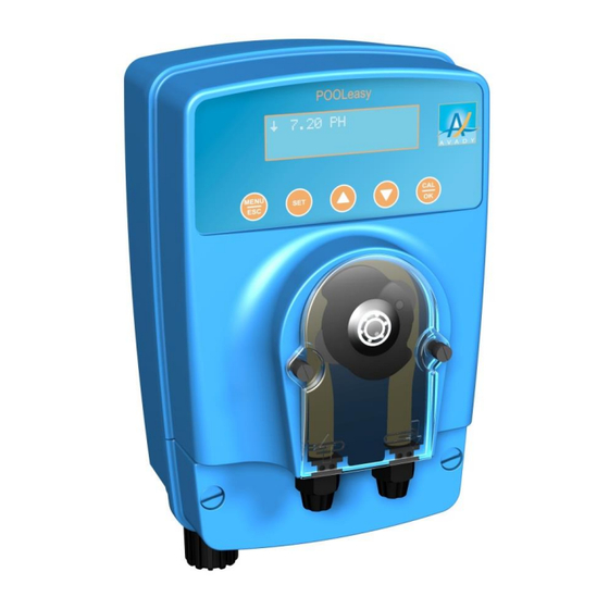
2. Description of pump The POOLeasy pH is characterised by its capacity to measure the pH value (between pH 0 and 14) thanks to its sensor placed in a filtration circuit that analyses your pool's water. As a function of the value measured, the POOLeasy PH injects, using its dosing pump, the quantity of reagent necessary to maintain pool water balance. -
Page 8: Description Of Buttons
2.2 Description of buttons: Long press on the MENU button gives access to the installation configuration and short press on the ESC button allows user to exit current menu SET button pressed together with buttons 3 (▲) or 4 (▼) allows the modification of the setpoint value The ▲... -
Page 9: Alarms And Displayed Symbols
3. Alarms and displayed symbols Message Meaning Action / and \ alternatives The pump is in the process of dosing Dosing is underway but the pump is paused. The pause lasts 5 minutes maximum. CALIBRATION ERR. Calibration not possible Check state of calibration solution Clean the sensor Replace the sensor TANK EMPTY... -
Page 10: Principle Of Hydraulic And Electrical Installation
4.2 Principle of hydraulic and electrical installation. 4.2.1 Case of a POOLeasy pH connected to a permanent power supply and filtration detection with a salt chlorinator cell. Fig. 3 Description of callouts on Figure 3 A- POOLeasy pH B- 2-in-1 sensor holder placed on the main pipe prior to any salt chlorinator cell (H) or after all pool accessories (heating, etc.). -
Page 11: Case Of A Pooleasy Ph And Redox Connected To A Permanent Power Supply And Filtration Detection With A Salt Chlorinator Cell
4.2.2 Case of a POOLeasy pH and Redox connected to a permanent power supply and filtration detection with a salt chlorinator cell. Fig. 4 Description of callouts in Figure 4 A- POOLeasy pH B- 2-in-1 sensor holder placed on the main pipe after all pool accessories (heating, etc.). The guide collars B for the pH unit and H for the Redox unit shall be separated by 1 cm at most allowing the two injection catheters to join at the exit of the H sensor holder. -
Page 12: Unit Installation
We therefore recommend that you start your installation with this step. STEP 3 : Drill a hole in the pipe using tool F POOLeasy pH + POOLeasy RX... -
Page 13: Step 4 : Probe Holder Preparation
Min 15° Min 15° STEP 4 : Probe holder preparation 4.1. Remove the cap & storage 4.2. Mount the o-ring (H) under the probe holder (B) -
Page 14: Step 5 : Place The Probe Holder (B) By Inserting The Injection Tube In The Direction Of The Waterflow
STEP 5 : Place the probe holder (B) by inserting the injection tube in the direction of the waterflow... -
Page 15: Step 6 : Securization On The Pipe
STEP 6 : Securization on the pipe 1) Ø50 pipe 2) Ø63 pipe... - Page 16 Vertical :...
-
Page 17: Step 7: Electrical Circuit
STEP 7: Electrical circuit 1. Connect the cable i (without filtration) detection plug, in the electrical box D present on your pool. auxiliary contact This cable must be connected to an of the filtration starter contact. The voltage will be 230V on the cable terminals when the filtration pump is on. -
Page 18: Step 9 A: Calibration Of The Ph Sensor
STEP 9 a: Calibration of the pH sensor - Remove the sensor from its soaking water indicated in Section 4.3, Step 2, and remove any excess water. Hold down the CAL/OK button for 5 SECONDS. PRESS THE ESC KEY AT ANY TIME TO EXIT THE CALIBRATION PROCEDURE PLACE THE SENSOR IN THE pH7 SOLUTION, SHAKE, LEAVE INSIDE WITHOUT TOUCHING... -
Page 19: Step 9 B: Calibration Of The Redox Sensor
STEP 9 b: Calibration of the Redox sensor - Remove the sensor from its soaking water indicated in Section 4.3, Step 2, and remove any excess water. Hold down the CAL/OK button for 5 SECONDS. PRESS THE ESC KEY AT ANY TIME TO EXIT THE CALIBRATION PROCEDURE PLACE THE SENSOR IN THE 475 mV SOLUTION, SHAKE, LEAVE INSIDE WITHOUT TOUCHING... -
Page 20: Step 10 : Installation Of The Short Probe (80Mm.)
STEP 10 : Installation of the short probe (80mm.) -
Page 21: Step 11: Hydraulic Circuit
3: Hand tighten the nut onto the connector STEP 12: Installation complete At this stage, the POOLeasy pH or Redox is ready for use without any further adjustments in most cases. Default pH values - Setpoint at pH 7.4... -
Page 22: Advanced Unit Settings
5. ADVANCED UNIT SETTINGS 5.1 Setpoint adjustment HOLD DOWN THE SET BUTTON and using the ▼ or ▲ buttons ADJUST THE VALUE SETPOINT VALUE pH 7.4 WHEN THE SET BUTTON IS RELEASED, THE VALUE WILL BE MEMORIZED 5.2 SETTINGS MENU Once inside the menu, use the ▼... -
Page 23: Pooleasy Settings In Ph Mode
5.2.1 POOLeasy settings in pH mode To set your POOLeasy in pH mode, refer to the previous section (5.0) MEASUREMENT TYPE Choice of reagent for dosing between DOSING MODE acid (pH-) and alkaline (pH+) ACID (pH-) Flowrate setting for pump on the unit PUMP FLOWRATE 1.5 L/h (1.5 or 3 L/h) -
Page 24: Pooleasy Settings In Redox Mode
5.2.2 POOLeasy settings in REDOX mode To set your POOLeasy in REDOX mode, refer to Section (5.0) MEASUREMENT TYPE REDOX Flowrate setting for pump on the PUMP FLOWRATE 1.5 L/h unit (1.5 or 3 L/h) Setting of pump activation time in PUMP ACT. -
Page 25: Guide For Setting Activation Time For The Ph Or Redox Pumps
5.2.3 Guide for setting activation time for the pH or Redox pumps Water volume Pump Acti Time Pump Acti Time S / 0.1 pH S / mV From 1 to 10 From 11 to 20 From 21 to 40 From 41 to 80 From 91 to 120 From 130 to 150 The values given in this table are indicative and should be adjusted as a function of the configuration and... -
Page 26: Pooleasy Standby Mode
When the unit is in an alarm state, the following screen is displayed Simply press CAL/OK to cancel the ***** alarm. OVERDOSING ALARM 5.3 POOLeasy standby mode To place the POOLeasy in standby mode, press the ▲and ▼ keys simultaneously for 5 seconds. To exit standby mode, repeat the same operation. -
Page 27: Maintenance
7. Maintenance 7.1 Replacement of the peristaltic tube Fig. 13 7.2 Maintenance of chlorine injection valve. Clean the injector tube from chlorine deposit with acid water or replace PVC tube. -
Page 28: Electrode Maintenance
7.3 Electrode maintenance 7.3.1. General remarks Over time, in addition to normal electrode wear, depending on usage and degree of hardness of water, the measurement will deteriorate. A thin layer of limescale, together with other elements present in the pool water, will be deposited on the sensitive elements of the sensor. -
Page 29: Installation Of A Long Probe (120Mm.)
7.3.2 Installation of a long probe (120mm.) -
Page 30: Pooleasy Winter Shutdown
7.4 POOLeasy winter shutdown It is important to know that for the winter shutdown of your unit, it is the peristaltic tube that needs protecting. It is then recommended to pump clean water to rinse the peristaltic tube 7.5 Sensor winter shutdown ... -
Page 31: Spare Parts List
8. Spare parts list Fig. 14 Code Description of parts AYAC100054 MET motor, 20 RPM, type B AYAC100069 Peristaltic tube, type B AYAC100056 Roller holder, type B 4/5/6 AYFA0009 Bearing kit/B cover/screw AYAC08AC01 pH electrode AYAC08BC01 Rx electrode AYFA00011 Complete 2-in-1 sensor holder AYFA00004 Sensor-holder cap AYAC100020... - Page 32 NOTES AVADY POOL - 9, Chaussée Jules César, Bâtiment 4 Hall 406 - 95520 OSNY – France Tel : +33 (0)1 34 48 16 03 Fax : +33 (0)1 78 76 73 95 Email : contact@avadypool.com Web : www.avadypool.com Installation and operating instructions are included with the product when purchased new. They can also be found on our website.
Need help?
Do you have a question about the POOLeasy pH and is the answer not in the manual?
Questions and answers