Table of Contents
Advertisement
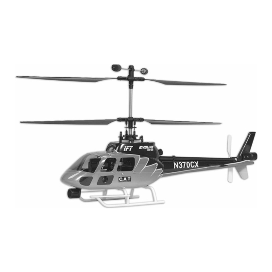
Specifications
Length:
Height :
Main Rotor Diameter:
Weight with Battery:
Main Motor:
Battery:
Charger:
Transmitter:
On‐Board Electronics:
18.3 in (465mm)
10.4 in (265mm)
18.0 in (460mm)
16.0 oz (455g)
370 (2 installed)
800mAh 3S 11.1V LiPo (included with RTF, required for RFR)
3S 11.1V LiPo DC balancing and AC adapter (included with
RTF, required for RFR)
5‐channel 2.4GHz (included with RTF, required for RFR)
Receiver (installed in RTF, required for RFR), 3‐in‐1 control
unit with 2 ESCs/mixer/gyro, Collision Avoidance
Technology module and sensors (installed in RTF and RFR)
Instruction Manual
1
Advertisement
Table of Contents

Subscribe to Our Youtube Channel
Summary of Contents for IFT Evolve 300 CX
- Page 1 Instruction Manual Specifications Length: 18.3 in (465mm) Height : 10.4 in (265mm) Main Rotor Diameter: 18.0 in (460mm) Weight with Battery: 16.0 oz (455g) Main Motor: 370 (2 installed) Battery: 800mAh 3S 11.1V LiPo (included with RTF, required for RFR) Charger: 3S 11.1V LiPo DC balancing and AC adapter (included with RTF, required for RFR) Transmitter: ...
-
Page 2: Table Of Contents
Table of Contents Introduction .............................. 3 Safety Precautions and Warnings ...................... 3 FCC Information ............................ 4 Evolve 300 CX RTF (Ready‐To‐Fly) Contents ..................... 5 Evolve 300 CX RFR (Ready‐For‐Receiver) Contents .................. 5 Required to Complete.......................... 6 Installing the Receiver (RFR version only) .................... 6 Before the First Flight Checklist (RTF version only) .................. 8 Flight Checklist ............................ 8 LiPo Battery Warnings and Usage Guidelines .................. 9 Charging the LiPo Flight Battery (RTF version only) ................ 10 Installing the Transmitter Batteries (RTF version only) ................ 15 Transmitter Details (RTF version only) .................... 15 Transmitter Dual Rates (RTF version only) ..................... 16 Flight Controls and Trimming ......................... 17 Installing and Removing the LiPo Flight Battery .................. 22 Control Unit Initialization and Arming .................... 23 Motor Control Test .......................... 26 Collision Avoidance Technology (C.A.T.) .................... 26 Selecting a Flying Area .......................... 34 Flying (General) ............................ 35 Flying Outdoors ... -
Page 3: Introduction
Introduction The Innovative Flight Technologies (IFT)™ Evolve 300 CX is perfect for first‐time and experienced pilots looking for a larger CX heli they can fly indoors and outdoors too. It’s much larger than typical ultra‐micro and micro class CX helis for improved visibility and performance when flying outdoors in winds up to 5‐10mph, yet the innovative and IFT‐ exclusive Collision Avoidance Technology (C.A.T.) also makes it possible to fly indoors in spaces where you may never comfortably fly most other micro class helis. Equipped with a coaxial, counter‐rotating blade design that offers excellent control and unsurpassed stability, the Evolve 300 CX will have any first‐time pilot hovering like a pro in no time while digital servos and powerful 370 motors coupled to a 3S 11.1V LiPo battery offer plenty of power and precise control for experienced pilots. The scale body is factory‐finished in an eye‐catching and highly visible trim scheme, plus the heli arrives 100% factory‐ assembled and ready to fly right out of the box! The Evolve 300 CX is available in RTF (Ready‐To‐Fly) and RFR (Ready‐For‐Receiver) versions that include a factory‐installed C.A.T. module and ultrasonic sensors plus an advanced 3‐in‐1 control unit and 7.5‐gram digital sub‐micro servos. The RFR version is ready for you to install a receiver compatible with your favorite transmitter while the RTF version includes everything needed to fly right out of the box – from AA batteries for the 5‐channel 2.4GHz transmitter and a 6‐channel receiver to the 800mAh 3S 11.1V LiPo battery, DC balancing charger and AC adapter there’s nothing extra to buy! And although the Evolve 300 CX is ready to fly right out the box, please take the time to read through this manual for more information on battery safety and charging, flight controls, the Collision Avoidance Technology and more before proceeding with your first flight. Please also visit our web site at www.IFTRC.com for additional information including potential product bulletins, videos and more. Safety Precautions and Warnings Failure to use this product in the intended manner as described in the following instructions can result in damage and/or personal injury. A Radio Controlled (RC) ... -
Page 4: Fcc Information
As the user of this product you are solely and wholly responsible for operating it in a manner that does not endanger yourself and others or result in damage to the product or the property of others. This model is controlled by a radio signal that is subject to possible interference from a variety of sources outside your control. This interference can cause momentary loss of control so it is advisable to always keep a safe distance from objects and people in all directions around your model as this will help to avoid collisions and/or injury. • Never operate your model if the voltage of the batteries in the transmitter is too low. • Always operate your model in an open area away from obstacles, people, vehicles, buildings, etc. • Carefully follow the directions and warnings for this and any optional support equipment (chargers, rechargeable batteries, etc.). • Keep all chemicals, small parts and all electronic components out of the reach of children. • Moisture causes damage to electronic components. Avoid water exposure to all electronic components, parts, etc. not specifically designed and protected for use in water. • Never lick or place any portion of the model in your mouth as it could cause serious injury or even death. FCC Information This device complies with part 15 of the FCC rules. Operation is subject to the following two conditions: (1) This device may not cause harmful interference, and (2) this device must accept any interference received, including interference that may cause undesired operation. Caution: Changes or modifications not expressly approved by the party responsible for compliance could void the user’s authority to operate the equipment. This product contains a radio transmitter with wireless technology which has been tested and ... -
Page 5: Evolve 300 Cx Rtf (Ready-To-Fly) Contents
Evolve 300 CX RTF (Ready-To-Fly) Contents Item Description Not Available Separately .. E volve 300 CX RTF Airframe IFLH1305 ...... M P5H 5‐Channel Helicopter Transmitter, Mode 2 Not Available Separately .. A A Batteries (4pcs) IFLB8003S20J ..... 8 00mAh 3‐Cell/3S 11.1V 20C LiPo Battery, JST Connector IFLC308C ...... 3 08C 3‐Cell/3S 11.1V LiPo, 0.8‐Amp DC Balancing Charger IFLC1215PS ...... 1 215PS 100‐240V AC to 12V DC Adapter, 1.5‐Amp Power Supply Not Shown ...... S pare Upper and Lower Main Rotor Blade Sets (1 pair of each) ... -
Page 6: Required To Complete
Required to Complete The Evolve 300 CX RTF (Ready‐To‐Fly) version includes everything needed to fly right out of the box. There’s nothing extra to buy or provide! The Evolve 300 CX RFR (Ready‐For‐Receiver) version requires the following items: 5+ channel transmitter (with suitable range if you plan to fly outdoors) 5+ channel receiver (compatible with the transmitter that will be used) 3‐Cell/3S 11.1V 800mAh LiPo battery (IFLB8003S20J or similar to fit the battery holder) LiPo battery charger (compatible with the battery that will be used) Installing the Receiver (RFR version only) The Evolve 300 CX RFR (Ready‐For‐Receiver) version is fully‐assembled and test‐flown at the factory (like all RTF version models). After test flying is complete the receiver is removed and the wire leads that will connect to your chosen receiver are left located inside the nose of the body. Select a suitable 5+ channel receiver compatible with the transmitter you’ve chosen to use then locate the wire leads and connectors (5 total) that must be connected to the receiver. Depending on the available length of the wire leads, as well as the size and shape of your receiver, determine if the receiver can be mounted on the top or bottom of the plastic mounting tray attached to the main frame (located inside the body near the nose of the helicopter). When possible we recommend installing the receiver on top of the tray and in front of the factory‐installed 3‐in‐1 control unit. ... - Page 7 Connect the ‘Throttle (THRO)’ lead to the ‘throttle’ channel of the receiver (channel 3/CH3 for Futaba and Hitec transmitters/receivers) Connect the ‘Aileron (AILE)’ lead to the ‘aileron’ channel of the receiver (channel 1/CH1 for Futaba and Hitec transmitters/receivers) Connect the ‘Elevator (ELEV)’ lead to the ‘elevator’ channel of the receiver (channel 2/CH2 for Futaba and Hitec transmitters/receivers) Connect the ‘Rudder (RUDD)’ lead to the ‘rudder’ channel of the receiver (channel 4/CH4 for Futaba and Hitec transmitters/receivers) Connect the ‘Gear (GEAR)’ lead to the ‘gear’ channel of the receiver (channel 5/CH5 for Futaba and Hitec transmitters/receivers) NOTE: The ‘Gear’ lead can also be connected to almost any channel that features a suitable 2‐position switch (recommended), ‘slider’ switch or rotating knob on the transmitter. This channel is used to control the Collision Avoidance Technology (C.A.T.) module in order to turn the technology on or off remotely from the transmitter (please see the ‘Collision Avoidance Technology’ section of this manual for more information). After making the proper connections it’s a good idea to test the controls before installing the receiver. Please see the ‘Flight Controls and Trimming’ and ‘Collision Avoidance Technology’ sections of this manual for more information. IMPORTANT NOTE: We strongly recommend to disconnect the wire leads/connectors for BOTH motors from the 3‐in‐1 control unit whenever testing the controls. Make note of the positions and polarities of the wire leads/connectors before disconnecting them in order to ensure you can reconnect them for proper operation after the control test is complete and before proceeding with your first flight. After confirming the controls are responding properly, carefully route the receiver and wire leads into the nose of the helicopter and mount the receiver to the tray using the two‐sided foam tape. In most cases it will typically be best to route the receiver and wire leads through the opening in the bottom of the body, but in some cases (depending on the size/shape of the receiver and the available length of the wire leads) it may be possible to route them ...
-
Page 8: Before The First Flight Checklist (Rtf Version Only)
Before the First Flight Checklist (RTF version only) PLEASE NOTE: This checklist is NOT intended to replace the content included in this instruction manual. Although it can be used as a quick start guide, we strongly suggest reading through this manual completely before proceeding. Remove and inspect all contents Connect the DC charger to a suitable power source (the included AC adapter or another suitable power supply, battery or DC power source) Begin charging the LiPo flight battery (connect it to the charger) Install the four (4) AA batteries in the transmitter and turn it on Install the LiPo flight battery in the helicopter (after it’s been fully charged) and connect it to the control unit Test the controls to confirm proper operation Familiarize yourself with the controls Find a suitable area for flying Flight Checklist PLEASE NOTE: This checklist is NOT intended to replace the content included in this instruction manual. Although it can be used as a quick start guide, we strongly suggest ... -
Page 9: Lipo Battery Warnings And Usage Guidelines
LiPo Battery Warnings and Usage Guidelines IMPORTANT NOTE: Lithium Polymer (LiPo) batteries are significantly more volatile than the alkaline, NiCd or NiMH batteries also used in RC applications. All instructions and warnings must be followed exactly to prevent property damage and/or personal injury as mishandling of LiPo batteries can result in fire. By handling, charging or using the included LiPo battery you assume all risks associated with LiPo batteries. If you do not agree with these conditions please return the complete product in new, unused condition to the place of purchase immediately. And although the 800mAh 3‐Cell/3S 11.1V 20C LiPo Battery (IFLB8003S20J) included with the RTF version Evolve 300 CX is intended to be charged safely using the included 3‐Cell/3S 11.1V LiPo, 0.8‐Amp DC Balancing Charger (IFLC308C) you must read the following safety instructions and warnings before handling, charging or using the LiPo battery. • You must charge the LiPo battery in a safe area away from flammable materials. • Never charge the LiPo battery unattended at any time. When charging the battery you should always remain in constant observation to monitor the charging process and react immediately to any potential problems that may occur. • After flying/discharging the battery you must allow it to cool to ambient/room temperature before recharging. • To charge the LiPo battery you must use only the included 3‐Cell/3S 11.1V LiPo, 0.8‐ Amp DC Balancing Charger (IFLC308C) or a suitably compatible LiPo battery charger. Failure to do so may result in a fire causing property damage and/or personal injury. DO NOT use a NiCd or NiMH charger. • ... -
Page 10: Charging The Lipo Flight Battery (Rtf Version Only)
• When transporting or temporarily storing the battery, the temperature range should be from approximately 40–100°F. Do not store the battery or model in a hot garage, car or direct sunlight whenever possible. If stored in a hot garage or car the battery can be damaged or even catch fire. • Do not over‐discharge the LiPo battery. Discharging the LiPo battery too low can cause damage to the battery resulting in reduced power, flight duration or failure of the battery entirely. LiPo cells should not be discharged to below 3.0V each under load. In the case of the 3‐Cell/3S 11.1V LiPo battery used to power the Evolve 300 CX you will not want to allow the battery to fall below 9.0V during flight. The 3‐in‐1 control unit does not feature a low voltage cutoff (LVC) of any type so it’s important for you to be aware of the power level of the LiPo battery during flight. If you ever find that more than the typical amount of throttle/power is required to hover and/or the helicopter will not ascend/climb even at full power you should land the model and disconnect the battery immediately to prevent over‐discharge. Continued discharging can cause permanent damage to the LiPo battery resulting in reduced power output and/or shortened flight durations during subsequent flights (or failure of the battery entirely). Charging the LiPo Flight Battery (RTF version only) You must charge the included 800mAh 3‐Cell/3S 11.1V 20C LiPo Battery (IFLB8003S20J) using only the included 3‐Cell/3S 11.1V LiPo, 0.8‐Amp DC Balancing Charger (IFLC308C) or a suitably compatible LiPo battery charger. Charging the LiPo battery using a non‐LiPo battery compatible charger (such as a NiCd or NiMH battery charger), or even a different LiPo ... - Page 11 NOTE: When using the 1215PS AC adapter/power supply the charger is protected to prevent damage if the alligator clips at the end of the input power leads touch. However, please take care to ensure that the alligator clips do not cause shorting of the LiPo flight battery, AC adapter/power supply, etc. by keeping them clear. PLACE THE 308C CHARGER ON A FLAT, SMOOTH AND HEAT‐RESISTANT SURFACE. It’s important that air is able to circulate around the case of the charger during the charging process in order to keep it from over‐heating. DO NOT place the charger on carpeted or other similar surfaces that may prevent air from circulating around all sides of the charger. Also, DO NOT place the charger in direct sunlight before, during or after use. Connect the white 4‐pin connector from battery (also typically referred to as the ‘balance connector’) to the mating connector on the charger. YOU MUST BE CAREFUL TO ENSURE PROPER POLARITY BEFORE MAKING THE CONNECTION. Reference the markings on the charger and ensure that the black color negative/ground wire lead is oriented so it’s toward the right‐hand side of the connector on the charger. And although the connectors are ‘keyed’ to minimize the risk of a reverse polarity connection, if you force them it is possible to make connection with incorrect polarity potentially causing damage to the battery and/or charger. When the connectors are properly aligned for correct polarity, connecting them should require only a moderate amount of pressure to achieve the ‘click’ that indicates a secure connection. ...
- Page 12 When the battery is connected to the charger securely and with the proper polarity both the red color and green color LED indicators will glow solid. The battery will be charging anytime the green LED indicator is glowing solid. The red and green status LEDs also indicate the following (this information is also listed on the label of the charger): Red Flashing LED Only: The charger is powered on but no battery is connected Red and Green Solid LEDs: A battery is connected and charging Red Solid LED Only: The charge process is complete Red and Green Flashing LEDs: An error occurred during the charge process It will take approximately 1.0–1.5 hours to fully charge a mostly or fully discharged battery (NOTE: See the following information in this section for more details regarding optional ‘fast’ charging that can reduce charge times to as little as 30‐45 minutes). And when the battery is fully charged the green LED indicator will stop glowing entirely. When the green LED indicator is no longer glowing you can disconnect the battery from the charger as it is now fully charged and ready for use. NOTE: The LiPo battery included with your model will arrive partially charged. For this reason the initial charge may only take approximately 30–45 minutes. ...
- Page 13 NOTE: It’s safer and better for the longevity of the battery to store it only partially charged for any length of time. Storing the battery at approximately 50% charge (which is approximately 3.85V per cell) is typically best; however, it will take some careful management of the charge time and the use of a volt meter to achieve this voltage. If you have the equipment and skills to achieve the 50% charge level for storage it is recommended. If not, simply be sure to not store the battery fully charged whenever possible. In fact, as long as the battery will be stored at approximately room temperature and for no more than a few weeks before the next use, it may be best to store the battery in the discharged state after the last flight (as long as the battery was not over‐discharged on the last flight). Charge Errors and Indications In the event that both the red and green LEDs flash an error has occurred during the charge process. Some examples of charge errors and their indications include: • Alternating flashing of the red and green LEDs indicates that the charge process has been interrupted. If input power to the charger has been interrupted due to a drop in voltage/current output or disconnection from the power source disconnect the battery from the charger. Check to make sure that the input power plug from the AC adapter/power supply is connected or that the alligator clips are firmly and properly attached to the power source. You should also check to be sure that the power source is providing the proper amount of voltage and current required to power the charger reliably. After confirming the input power connection is secure and that the power source is delivering the necessary voltage and current, connect the battery to the charger again. Continue to monitor the charge process to ensure that no further charge errors occur. • Simultaneous flashing of the red and green LEDs indicates that the voltage of the LiPo battery (or even just one cell in the battery) is too low to allow the charge process to begin. In this case the battery may have been over‐discharged due to flying the model too long (please see the ‘LiPo Battery Warnings and Usage Guidelines’ section of this manual for more information) or that one or more cells in the battery are damaged/have failed. ...
- Page 14 Optional ‘Fast’ Charging The included 800mAh 3‐Cell/3S 11.1V 20C LiPo Battery (IFLB8003S20J) can be ‘fast’ charged at rates up to 2C (2x the Capacity of the battery; 2 x 800mAh = 1600mAh = 1.6A) when using approved and compatible LiPo battery chargers. It will take approximately 30‐45 minutes to fully charge a mostly or fully discharged (not over‐discharged) battery when charging at 2C. For ‘fast’ charging we recommend using the Radient™ Ascend charger (RDNA0002). This charger is capable of charging the included LiPo battery at rates up to 2C/1.6A and can also be used to charge other higher and lower capacity LiPo, NiCd and NiMH batteries. The Ascend charger is equipped with a ‘Tamiya‐style’ connector (use a ‘Tamiya to JST’ adapter to connect the main power leads of the included LiPo battery) and is compatible with the JST‐XH (balance) connector installed on the battery. It can be powered from a 100–240V AC outlet or from a 12–15V DC power source, such as a 12V ‘car’ battery, for quick and convenient charging at the field or beyond. You can find the Radient Ascend charger at HobbyTown USA® stores and www.HobbyTown.com. ...
-
Page 15: Installing The Transmitter Batteries (Rtf Version Only)
Installing the Transmitter Batteries (RTF version only) Install the four (4) included AA batteries in the back of the transmitter by first removing the battery compartment cover/door. Ensure proper polarity of the batteries before installing them (as noted by the markings molded into the battery compartment), then re‐install the compartment cover/door. Check the voltage of the batteries and operation of the transmitter by switching the power switch ON (slide it upward). The LED indicator near the bottom left‐hand corner should blink rapidly then glow solid red while the LCD screen powers on to display the voltage of the AA batteries. These indications confirm the transmitter is powered on and functioning correctly. NOTE: If at any time the voltage displayed on the LCD screen falls to 4.5V or less it will be necessary to replace the AA batteries with new ones. Transmitter Details (RTF version only) The RTF version Evolve 300 CX includes an MP5H 5‐Channel Helicopter Transmitter equipped with 2.4GHz technology, dual rates, servo reversing and an LCD screen (the RFR version requires a 5+ channel transmitter/receiver). Antenna Position/Orientation The RF output signals transmit best/strongest from the shaft of the antenna rather than from the tip. As a result you should never point the tip of the antenna directly at the model. Also, the transmitter antenna can be rotated up to 180° and folded up to 90° so be sure to hold the transmitter and position the antenna as needed to ensure the best possible signal transmission. ... -
Page 16: Transmitter Dual Rates (Rtf Version Only)
Control/Servo Reversing The MP5H transmitter features control/servo reversing functionality for the aileron, elevator, throttle and rudder channels. The control/servo directions were set correctly for use with the Evolve 300 CX at the factory, however, in case the controls are operating in the wrong direction (or you use the transmitter/receiver for other models later on) simply change the position of control/servo reversing switch for the channel(s) as needed. The switches are located under the cover/door near the bottom right‐hand corner of the transmitter. Gear Switch The switch located on the top left ‘shoulder’ of the transmitter is used to toggle the ‘GEAR’ ) channel. For the RTF version Evolve 300 CX the GEAR switch/channel can be used to turn the Collision Avoidance Technology (C.A.T.) on or off remotely from the transmitter before and/or during flight. Please see the ‘Collision Avoidance Technology’ section of this manual for more information. Rate Switch The switch located on the top right ‘shoulder’ of the transmitter is used to toggle between the ‘Dual Rates’ (high and low) available for the aileron and elevator controls/channels. Please see the ‘Transmitter Dual Rates’ section of this manual for more information. Transmitter Dual Rates (RTF version only) The ‘RATE’ switch (located on the top right ‘shoulder’ of the MP5H transmitter) is used to the toggle between the ‘High’ (HI) and ‘Low’ (LO) control rates, also known as ‘Dual Rates’, available for the aileron and elevator controls/channels. When the switch is in the ‘HI’ position (toward the back of the transmitter) the controls are allowed to reach their maximum (high) rates/values. This mode is typically preferred by experienced pilots interested most in maximum control authority. When the switch is in the ‘LO’ position (toward the front of the transmitter) the maximum control rates/values will be reduced for the aileron and elevator channels. This is typically preferred by (and recommended best for) first‐time, low‐time and other pilots interested in a ... -
Page 17: Flight Controls And Trimming
Flight Controls and Trimming In the event you are not familiar with the controls of the Evolve 300 CX please take the time to familiarize yourself with them as follows and before proceeding with your first flight: The left‐hand stick on the transmitter controls both the throttle (climb/descend) and rudder (yaw left/right) channels. When the left‐hand stick (also known as the ‘throttle’ stick) is in the lowest possible position the rotor blades will not spin. Moving the stick upward will increase the speed/RPMs of the rotor blades. Increasing the speed/RPMs of the rotor blades will cause the model to climb. Decreasing the speed/RPMs of the rotor blades by lowering the left‐hand stick will cause the model to descend. After lifting the helicopter off the ground you can maintain altitude in ‘hover’ by carefully moving the left‐hand stick up and down slightly as needed so the helicopter will not climb or descend. ... - Page 18 The throttle trim lever (located immediately to the right of the left‐hand/throttle stick) can be used to adjust the throttle control/channel output value for a given stick position. For example, raising the throttle trim lever will make it possible to maintain altitude with the helicopter when the left‐hand/throttle stick is in a lower position. The throttle trim can also be used to increase the maximum amount of power available when the left‐hand stick is raised to the highest possible position. We do not typically recommend raising the throttle trim when flying indoors (especially when flying under relatively low ceilings) but it can be helpful to raise the throttle trim when flying outdoors. IMPORTANT NOTE: If you do raise the throttle trim lever you MUST remember to lower it AND the throttle stick to their lowest possible positions IMMEDIATELY in the event of a crash or rotor blade strike. Failure ...
- Page 19 Moving the left‐hand stick to the right will turn (yaw) the nose of the helicopter to the right about the axis of the main shaft. This is accomplished by increasing the speed/RPMs of the upper set of main rotor blades while decreasing the speed/RPMs of the lower set of main rotor blades. The rudder trim lever (located immediately below the left‐hand stick) can be used to help keep the nose of the helicopter from turning (yawing) to the left or right when ‘hovering’ and without any left‐hand stick/rudder control input. For example, if the nose of the helicopter turns to the right when hovering slide the rudder trim lever to the left until the nose of the helicopter stays as close to ‘straight’ as possible with no further rudder control/trim input. NOTE: It is not uncommon for the nose of most CX (coaxial) helicopters to drift slightly in one direction or the other throughout a flight (as the motors heat up and the battery’s output voltage decreases). This means you may find it necessary to adjust the rudder trim lever position/setting slightly throughout a flight but typically it’s not more than a few ‘clicks’ one way or the other. Also, please see the ‘Proportional Mix Trimmer Pot’ and ‘Gyro Gain Trimmer Pot’ sections of this manual for more information on other potential adjustments that can be made to fine‐ tune rudder/tail control and response. ...
- Page 20 The right‐hand stick controls both the elevator (pitch fore/aft) and aileron (roll) channels. Pushing the stick upward/forward will pitch the nose of the helicopter downward, allowing it to be flown forward. This is accomplished by having the elevator (left‐hand) servo push the swashplate upward. Pulling the right‐hand stick downward/backward will pitch the tail of the helicopter downward, allowing it to be flown backward. This is accomplished by having the elevator (left‐hand) servo pull the swashplate downward. The elevator trim lever (located immediately to the left of the right‐hand stick) can be used to help keep the helicopter from drifting forward or backward when hovering and with no right‐ hand stick/elevator control input. For example, if the helicopter drifts forward when hovering slide the elevator trim lever downward until the helicopter hovers as level as possible without drifting forward. ...
- Page 21 Moving the right‐hand stick to the left will roll the helicopter to the left, allowing it to be flown to the left. This is accomplished by having the aileron (right‐hand) servo push the swashplate upward. Moving the right‐hand stick to the right will roll the helicopter to the right, allowing it to be flown to the right. This is accomplished by having the aileron (right‐hand) servo pull the swashplate downward. The aileron trim lever (located immediately below the right‐hand stick) can be used to help keep the helicopter from drifting left or right when hovering and with no right‐hand stick/aileron control input. For example, if the helicopter drifts to the right when hovering slide the aileron trim lever to the left until the helicopter hovers as level as possible without drifting to the right. ...
-
Page 22: Installing And Removing The Lipo Flight Battery
Installing and Removing the LiPo Flight Battery After the LiPo flight battery has been fully charged it’s ready to be installed in the helicopter. Install the battery by sliding it carefully into the battery holder/landing gear mount (attached to the bottom of the main frame) through the opening on the bottom of the body and behind the rear landing gear strut. It’s important to install the battery with the wire leads and connectors oriented towards the BACK and LEFT side of the helicopter (when viewing it from behind) in order to keep them away from the wire leads for the rear ultrasonic sensor (which run down the right side of the body/helicopter). Slide the battery into the battery holder until it makes contact with the tab/‘stop’ near the front of the forward landing gear strut. QUICK TIP: If you find it difficult to install and remove the battery you can use scissors (we recommend ‘lexan’ type scissors available from most hobby shops) and/or a sharp knife (and extreme care to prevent personal injury!) to remove material and make the opening in the body wider and longer. To remove the LiPo flight battery (after carefully disconnecting it from the 3‐in‐1 control unit) start by pushing on the end near the tab/stop so it slides the battery out of the holder slightly. Then, pull on the sides of the battery (NOT on the wire leads!) while carefully holding the body out of the way to remove it from the mount/helicopter completely. QUICK TIP: You can install a ‘pull tab’ on the battery using tape to make it easier to remove from the holder/helicopter. ... -
Page 23: Control Unit Initialization And Arming
Control Unit Initialization and Arming The Evolve 300 CX is equipped with a compact and advanced 3‐in‐1 control unit. The control unit is a lightweight combination of two electronic speed controls (ESCs), a mixer and gyro. It’s also equipped with a gyro gain trimmer pot, proportional mix trimmer pot and LEDs that provide various indications. This checklist includes the steps you must follow to ensure proper initialization, arming and operation of the control unit: Before each flight you must ALWAYS turn the transmitter on BEFORE connecting the LiPo flight battery to the control unit. Never connect the battery to the control unit before powering the transmitter on first. And after each flight you should always disconnect the battery from the control unit before turning the transmitter off. The left‐hand/throttle stick AND the throttle trim lever must be set in their lowest possible positions in order for the control unit to initialize/arm properly. Failure to lower the stick and trim lever to the lowest possible positions can prevent the ESCs from arming and/or the gyro from initializing properly. Turn the transmitter on and confirm that the LED indicator blinks rapidly then glows solid red while the LCD screen powers on to display the voltage of the AA batteries. ... - Page 24 NOTE: If this will be the first flight, or the first flight following repairs, you should ‘center’ the rudder, elevator and aileron channel trim levers. AFTER INSTALLING THE BATTERY IN THE MOUNT/HELICOPTER YOU MUST BE CAREFUL TO ENSURE PROPER POLARITY BEFORE CONNECTING IT TO THE 3‐IN‐1 CONTROL UNIT. By orienting/aligning the wire leads of the battery and control unit so they’re ‘red to red’ and ‘black to black’ you’ll be able to make the connection with correct polarity Also, although the ‘JST’ connectors are ‘keyed’ to minimize the risk of a reverse polarity connection, if you force them it is possible to make connection with incorrect/reversed polarity potentially causing damage to the control unit and/or battery. When the connectors are properly aligned for correct polarity, connecting them should require only a minimal amount of pressure to achieve the light ‘click’ that indicates secure connection. With the LiPo flight battery connected to the control unit the LED indicators (on the control unit) will typically blink red three (3) times then blink green three (3) times. IMPORTANT NOTE: AFTER THE BATTERY IS CONNECTED TO THE CONTROL UNIT IT’S IMPORTANT TO NOT MOVE OR ROTATE THE HELICOPTER ONCE THE LED BEGINS TO BLINK GREEN CONFIRMING THAT THE INITIALIZATION PROCESS AND CALIBRATION OF THE GYRO HAS BEGUN. If you do move/rotate the helicopter too much while the LED is blinking green it may affect initialization/calibration of the gyro which could require significant rudder trim adjustments and/or prevent the gyro from working during the pending flight. If this happens you must disconnect the battery from the control unit and repeat the initialization/calibration process. ...
- Page 25 Also, it’s typically best to connect the battery to the control unit while the helicopter is sitting on a stable, flat and level surface rather than when holding it in your hands. When the LED indicator begins to glow solid green the control unit is initialized, armed and ready for flight. Use caution as the rotor blades will now spin with left‐hand/throttle stick input! DO NOT advance/raise the throttle stick or trim lever until you are clear of the rotor blades and ready to fly. In case the LED indicator does not glow solid green: If the LED indicator begins to glow solid red you have a positive Radio Frequency (RF) link between the transmitter and receiver but the throttle stick and/or throttle trim lever nay not be in their lowest possible positions. Check to see if both the throttle stick and throttle trim lever are in the lowest possible position, and if either or both are not, disconnect the battery from the control unit then lower the stick and/or trim as needed. Connect the battery to the control unit again and the LED indicator should blink red, blink green then glow solid green to indicate the control unit is initialized, armed and ready for flight. If the LED indicator continues to flash from green to red you do not have a positive RF link between the transmitter and receiver. First, check to be sure that the transmitter is powered on and that it has an adequate level of battery voltage/power. If the transmitter is already powered on, disconnect the battery from the control unit then turn the transmitter off. Follow the steps to bind/link the transmitter to the receiver (see the ‘Transmitter and Receiver Binding/Linking’ section of this manual for RTF version helicopters or the manual for your chosen transmitter/receiver for RFR version helicopters) and after confirming that the transmitter and receiver are properly bound/linked, connect the battery to the control unit again. The LED indicator should blink red, blink green then glow solid green to indicate the control unit is initialized, armed and ready for flight. After confirming the control unit has initialized and armed properly the Evolve 300 CX is ready to fly. However, please review the following information/sections of the manual BEFORE proceeding with your first flight. ...
-
Page 26: Motor Control Test
Motor Control Test To confirm proper control and operation of the motors, place the helicopter in an open area free of people and obstructions. And when everything is clear of the rotor blades, proceed with the following steps: Raise the left‐hand/throttle stick slowly and just high enough so that both sets of rotor blades begin to spin slowly. Then, note the direction that each set of rotor blades spins. The lower set of rotor blades should spin clockwise and the upper set of rotor blades should spin counterclockwise (when viewed from above). If either set of rotor blades are spinning in the wrong direction, disconnect the LiPo flight battery from the control unit then simply reverse the corresponding motor’s connector/plug polarity at the connection on the control unit. The proper polarity for each motor connection is marked on the case/housing of the control unit and it’s also helpful to note the following: The ‘front’ motor spins the lower set of rotor blades and should be connected to the lower motor connection/set of pins on the control unit. The ‘rear’ motor spins the upper set of rotor blades and should be connected to the upper motor connection/set of pins on the control unit. After confirming that both sets of rotor blades are spinning in the correct directions it’s important to confirm that the rotor blades respond properly to rudder (yaw) control inputs. With both sets of rotor blades spinning slowly move the left‐hand/rudder stick all the way to the right. This should cause the speed/RPMs of the upper rotor blades to increase, and the speed/RPMs of the lower rotor blades to decrease. Next, move the left‐hand/rudder stick all the way to the left. This should cause the speed/RPMs of the lower rotor blades to increase and the speed/RPMs of the upper main rotor blades to decrease. If both sets of rotor blades are not responding properly to rudder (yaw) control inputs, disconnect the LiPo flight battery from the control unit then simply switch the positions of motor connectors/plugs at the connections on the control unit. Note that the proper connections for each motor are listed above. ... - Page 27 The Evolve 300 CX is equipped with innovative and IFT‐exclusive Collision Avoidance Technology (C.A.T.). Designed and developed exclusively by IFT engineers, C.A.T. delivers functionality and performance never before seen in a ready‐to‐fly RC aircraft. Using state‐of‐ the‐art ultrasonic sensors and technology similar to that found in luxury automobiles for collision intervention and parking assistance, C.A.T. can automatically avoid collisions with a variety of obstacles including walls, furniture and more. This helps first‐time pilots avoid collisions and crashes when learning to fly while also giving low‐time and experienced pilots added confidence to fly in smaller indoor spaces. The advanced C.A.T. software offers selectable modes suitable for flying in larger and smaller indoor spaces and also makes it possible to turn the technology on or off remotely from the transmitter. Best of all the C.A.T. module and ultrasonic sensors are factory‐installed and ready to use right out of the box with no difficult assembly, setup or adjustments required! C.A.T. Functions and Performance When the C.A.T. module is activated (turned on) remotely from the transmitter ultrasonic sensors at the front, back and on each side of the helicopter can precisely measure the distance to obstacles and the control system can automatically apply inputs to avoid collisions. For example, when the front sensor detects an obstacle such as a wall, the control system will automatically apply backward elevator input to avoid a potential collision. ...
- Page 28 However, it is important to note that C.A.T. does not automatically avoid collisions with all obstacles in all conditions and circumstances. Factors including the material, size and shape of an obstacle/object, its position and angle relative to the sensor(s) and the speed the helicopter is traveling at can have an impact on detection and the corresponding response. For example the technology will best detect obstacles/objects with surfaces made from materials that better reflect ultrasound waves. Such obstacles/objects can include some walls, uncovered windows, furniture (cabinets, bookcases, desks, etc.) and others. Obstacles/objects with surfaces made from materials that can absorb ultrasound waves, including some fabric covered furniture, window curtains/drapes and others, will be more difficult to detect. One potential way to determine how well a particular obstacle/object can be detected is to follow the test procedure outlined in the ‘C.A.T. Testing’ section. Other factors can also have an impact on detection and the corresponding response of the technology. Some of these factors can include the obstacle’s/object’s size and shape as well as its position and angle relative to the sensor(s). For example the ‘smaller’ the surface of an obstacle/object is relative to the sensor(s) the less likely it is to be detected unless it’s more ‘directly’ in front of the sensor(s) . Also, the sensors will typically better detect an obstacle/object when the front (the side with the ‘mesh screen’) is as close to parallel to the surface of the obstacle/object as possible. However, the sensors can still detect some obstacles/objects even when they are not directly in front of and/or no surfaces are parallel to the sensors, albeit at limited/less range. Another important factor to consider is the speed at which the helicopter is traveling toward an obstacle/object. The faster the helicopter is moving the less time the technology will have to detect and respond. Even when an obstacle/object is made from a material that better reflects ultrasound waves, and has a relatively large surface that’s positioned directly in front of and parallel to the front of the sensor (such as a wall), if the helicopter is moving toward it too quickly the technology may not be able to detect it and respond in time to help prevent a collision. It is typically recommended to use the ‘Low (LO)’ control rate setting on the transmitter and/or minimal control inputs to keep the helicopter from traveling too quickly toward obstacles/objects whenever possible. Turning C.A.T. On and Off The advanced C.A.T. software offers selectable modes suitable for flying in larger and smaller indoor spaces (see the ‘HI and LO Mode Settings’ section for more information) and also makes it possible to turn the technology on and off remotely from the transmitter at any time. When using the MP5H transmitter included with the RTF version the ‘GEAR’ (channel 5) switch located on the top left ‘shoulder’ will turn the technology on/off. When the switch is in the ‘0’ position (toward the back of the transmitter) the technology will be OFF. When the ...
- Page 29 When using your transmitter/receiver of choice with the RFR version you can turn the technology on and off using the suitable 2‐position switch (recommended), ‘slider’ switch or rotating knob for the channel you connected the ‘Gear’ lead to when installing the receiver. Please see the ‘Installing the Receiver’ section of this manual for more information if needed. Also, if you are not sure which position the switch/knob must be in to turn the technology on or off, with the switch on the C.A.T. module set to the LO mode (see the ‘LO Mode’ section for more information), watch for the blue color LED to illuminate the inside of the case/housing for the C.A.T. module when the technology is turned ON (and be sure to note the corresponding switch/knob positions for on/off accordingly). HI and LO Mode Settings The C.A.T. module is equipped with a switch that allows it to be set to the available ‘HI’ (high) or ‘LO’ (low) modes. This switch is located on the side of the module that can be seen and accessed easily though the opening in the bottom of the body (near the nose). The module is delivered from the factory with the switch set to the HI mode position. However, before proceeding with your first flight be sure to read about each of the modes as follows, and, depending on your skill level, the size of the area you’ll be flying in and the number and type of obstacles/objects in the area, set the switch to the mode that will work best overall. HI Mode When the switch is set to the HI mode position, the technology will work to detect obstacles/objects from the furthest distance possible (as the technology, conditions and other factors allow). It will also respond more ‘firmly’ to avoid collisions with any obstacles/objects it detects. The actual distance of detection and the corresponding response will vary depending on the factors previously noted (in the ‘C.A.T. Functions and Performance’ section), however, it can be upwards of 3.3 feet (approximately 1 meter) for certain obstacles/objects in ideal conditions/circumstances. ...
- Page 30 We typically recommend using C.A.T. in the HI mode when flying in larger indoor spaces (approximately 15‐feet by 15‐feet and larger) and/or spaces containing fewer obstacles/objects. We also recommend that first‐time and low‐time pilots use C.A.T. in the HI mode (and the ‘Low (LO)’ control rate setting on the transmitter) whenever possible as it can help to better avoid potential collisions with more obstacles/objects and in more conditions/circumstances (compared to the LO mode). IMPORTANT NOTE: Before taking off/flying in the HI mode it is important to note that even when the ‘GEAR’ switch on the MP5H transmitter (or the switch/knob for the corresponding channel on your chosen transmitter) is set to the ON (1) position the technology will NOT be activated (turned on) until after the throttle stick has been raised above approximately the 1/3 position for 5 seconds. If you are taking off from an area that may have many obstacles/objects near the ground and/or surrounding the helicopter this 5 second delay should allow you enough time to comfortably take off and climb to a safe altitude above the obstacles/objects before the technology becomes active automatically. Also, the technology will turn off automatically, even when the ‘GEAR’ switch on the MP5H transmitter (or the switch/knob for the corresponding channel on your chosen transmitter) is set to the ON (1) position, any time you land the helicopter and/or lower the throttle stick below the 1/3 position. The technology will not be activated (turned on) again until after the stick has been raised above the 1/3 position for 5 seconds. LO Mode When the switch is set to the LO mode position, the technology will work to detect obstacles/objects from ‘closer’ distances and will respond less ‘firmly’ (compared to the HI mode) to avoid collisions with any obstacles/objects it detects. This makes it possible to still use the technology even when flying in smaller indoor spaces and/or spaces containing more obstacles/objects. The actual distance of detection and the corresponding response will vary depending on the factors previously noted, however, it can be upwards of 2.2 feet (approximately 0.7 meters) for certain obstacles/objects in ideal conditions/circumstances. We typically recommend using C.A.T. in the LO mode when flying in smaller indoor spaces (approximately 10‐feet by 10‐feet and larger) and/or spaces containing more obstacles/objects. It is also typically best to use the ‘Low (LO)’ control rate setting on the transmitter and/or minimal control inputs to keep the helicopter from traveling too quickly toward obstacles/objects whenever possible. IMPORTANT NOTE: In the LO mode, whenever the ‘GEAR’ switch on the MP5H transmitter (or the switch/knob for the corresponding channel on your chosen transmitter) is set to the ON (1) position the technology WILL be activated (turned on) at all times and regardless of ...
- Page 31 C.A.T. Testing It is possible (and recommended) to test the functions and performance of C.A.T. before actually flying the helicopter. It is easiest to test in the LO mode as you can keep the motors connected to the control unit (but be sure to use extreme caution as the rotor blades will spin with any left‐hand/throttle stick input!). However you can also test in the HI mode AFTER disconnecting the motors from the control unit, moving the corresponding switch on the transmitter to the ON position and raising the left‐hand/throttle stick to above approximately the 1/3 position for 5 seconds. You can test the function and performance of C.A.T. by keeping yourself and all obstacles/objects ‘clear’ of the sensors (holding the helicopter by the landing gear/skids, above your head and near the center of the room is one way to accomplish this). Then hold your open hand/palm or another similarly sized and relatively flat/solid object aligned in front of, parallel to and approximately 16‐20 inches (40–50 centimeters) away from each sensor to see the response (NOTE: If you hold your hand or the object closer than or farther than 16–20 inches away you may not see a consistent response during this test). And as long as the sensors are connected to the C.A.T. module and functioning correctly, you should note the following responses during the test: When you hold your hand or an object in front of the REAR sensor (SEN 1), the elevator (left‐hand) servo should push the swashplate upward (forward/down elevator control input). When you hold your hand or an object in front of the LEFT sensor (SEN 2), the aileron (right‐hand) servo should pull the swashplate downward (right aileron control input). When you hold your hand or an object in front of the FRONT sensor (SEN 3), the elevator (left‐hand) servo should pull the swashplate downward (backward/up elevator control input). When you hold your hand or an object in front of the RIGHT sensor (SEN 4), the aileron (right‐hand) servo should push the swashplate upward (left aileron control input). If the wrong servo responds and/or the servo responds in a different direction than noted above you should check to see if the corresponding sensor is connected to the correct channel/set of pins on the C.A.T. module. Or, if the servo does not respond at all it may be ...
- Page 32 helicopter closer to the obstacle/object until you hear and see the corresponding servo respond. This will give you an approximate indication of how well a particular obstacle/object can be detected. However, the actual distance of detection and the corresponding response when flying will vary depending on the factors previously noted (in the ‘C.A.T. Functions and Performance’ section). NOTE: You may notice that the servos seem to ‘twitch’ when testing the function and performance of C.A.T. without flying. This is normal and to be expected as a result of the high performance and sensitive nature of the technology. Gain Trimmer Pot The C.A.T. module is equipped with a ‘GAIN’ trimmer pot that can be used to adjust/fine‐tune the overall ‘sensitivity’ and response of the technology. This pot is set at the factory to provide good performance overall and does not typically need to be adjusted. However, you can remove the C.A.T. module from the body or make a small hole in the windshield to access the pot and use a small ‘straight’ blade screwdriver (preferably with a plastic tip) to adjust it. If you ever find that the helicopter ‘twitches’ when the technology is activated (turned on) and there are no obstacles/objects within the detection range of the sensors, you should decrease the gain until the helicopter no longer twitches: Turn the gain trimmer pot counterclockwise (‐) to decrease the gain. In some cases you can increase the sensitivity/response of the technology by increasing the gain: Turn the gain trimmer pot clockwise (+) to increase the gain. However, if you find that the helicopter ‘twitches’ in any direction after increasing the gain you should decrease it slightly and check again. C.A.T. Hints and Tips It is typically best to use the ‘Low (LO)’ control rate setting on the transmitter and/or minimal control inputs to keep the helicopter from traveling too quickly toward obstacles/objects whenever possible. ...
- Page 33 Do not fly through doorways, hallways or other relatively ‘narrow’ spaces with C.A.T. activated (turned on). The technology cannot always or immediately detect obstacles/objects that are relatively close to the sensors. In some cases the technology will not immediately detect obstacles/objects that are almost against to within a few inches (centimeters) away from the sensors. However, this is not typically problematic as detecting obstacles/objects beyond the span of the rotor blades/disk (approximately 9+ inches/23+ centimeters away from the main shaft) is the best way to prevent collisions that would damage the rotor blades and/or result in a crash. Do not attempt to fly more than one Evolve 300 CX with C.A.T. activated (turned on) in the same room. However, it is OK to fly more than one Evolve 300 CX in the same room as long as no more than one helicopter has C.A.T. activated (turned on) at any given time. If you ever find it necessary to remove then re‐install the C.A.T. module for any reason (possibly after a crash, when making repairs, for maintenance, etc.) it is important to ensure that you install it in the same approximate position (in the nose of the body) and orientation it was in when delivered from the factory. The C.A.T. module must always be installed as far away from the 3‐in‐1 control unit as possible to ensure the best possible interference‐free performance. NOTE: The ultrasonic sensors (transceivers) generate sound waves around 40kHz. Ultrasound/ultrasonic waves can disturb some animals including dogs. We recommend to avoid flying the helicopter around dogs as doing so may cause them to behave erratically or possibly even dangerously. IMPORTANT NOTE: Innovative Flight Technologies (IFT)/Firelands Group, LLC shall not assume or accept liability for any resulting damage or injury caused by this product or the user’s expected function/performance of C.A.T. By the act of use, setup or assembly, the user accepts all resulting liability. Please see the ‘Warranty, Support and Service’ section of this manual for more information. ...
-
Page 34: Selecting A Flying Area
Selecting a Flying Area The Evolve 300 CX is much larger than typical ultra‐micro and micro class CX helis for improved visibility and performance when flying outdoors, yet the innovative and IFT‐ exclusive Collision Avoidance Technology (C.A.T.) makes it possible to fly indoors too. However, before proceeding with your first flights indoors or out please be sure to review the details in this section to ensure you’re choosing suitable spaces and conditions to achieve the best possible performance and flying experience. IMPORTANT NOTE: If you are a first‐time or low‐time pilot we strongly recommend allowing a more experienced pilot to test fly and properly trim the model before attempting your first flight. A proven flyable and properly trimmed model is significantly easier and more enjoyable to fly! Please contact your local hobby shop and/or flying club to find a more experienced pilot near you. Indoor Flying Areas When flying indoors you’ll want to select an open area free of people and obstructions. We suggest an area with at least 15‐feet by 15‐feet of floor space and no less than 8‐foot ceilings when making your first few flights. After you’ve properly trimmed the helicopter and become familiar with its handling and capabilities, as well as the capabilities of C.A.T., you may be able to fly in other smaller and less open areas too. And while C.A.T. can help to automatically avoid collisions with a variety of obstacles/objects including walls, furniture and more (please see the ‘Collision Avoidance Technology’ section of this manual for more information) it’s always more fun to fly indoors in spaces that are larger and/or more open when possible. Outdoor Flying Areas/Conditions When flying outdoors it’s best to fly the Evolve 300 CX at a local park, schoolyard or other area that’s large enough and free of people and obstructions. We also suggest flying over grass as it’s a much more ‘forgiving’ surface that causes less damage in the unfortunate event of a crash. Do NOT fly in parking lots, crowded neighborhood areas or in areas that are not free of people and obstructions. ... -
Page 35: Flying (General)
After you’ve properly trimmed the helicopter in calm conditions and become familiar with its handling/capabilities it can be flown in very light (1–3mph) wind conditions. You can also increase the control authority and install the optional short length stabilizer flybar (IFLH1319X) to fly in winds up to 5– 10 mph (depending on your experience and comfort level). Please see the ‘Flying Outdoors’ section of this manual for more information. IMPORTANT NOTE: Do NOT fly on days when significant moisture, such as rain or snow, is present! Flying (General) Now that you’ve selected a suitable flying area you’re ready to fly! And when making your first flights we suggest following these steps: Slowly raise the left‐hand/throttle stick to increase the speed of the main rotor blades and until the model begins to lift off. Do NOT raise the stick too quickly as the model could climb too fast causing you to lose control and/or make contact with the ceiling or other objects above (this is one of the most common ways most first‐time pilots crash!). Lift the model approximately 24–30 inches (60–75 centimeters) off the ground and concentrate on ‘balancing’ the throttle stick position so the helicopter holds a steady hover altitude. It may also be helpful to make a few short ‘hops’ to an altitude of just a few inches until you’re familiar and more comfortable with the control inputs and trim settings required to maintain a steady hover and altitude. However, keep in mind that when only a few inches off the ground you’ll be in ‘ground effect’ which will cause the helicopter to move around more than it typically would at approximately 24–30 inches of altitude. You’ll find that it sometimes takes minor throttle adjustments to maintain altitude in hover. Remember to keep these adjustments as minimal as possible as large adjustments could result in a loss of control and/or a possible crash. While attempting to establish a low‐level hover out of ground effect (approximately 24–30 inches high or higher) you can check to see if any trim adjustments are required ... - Page 36 o If the nose of the helicopter is drifting to the left or right adjust the rudder trim. You can also adjust the proportional mix trimmer pot on the 3‐in‐1 control unit (please see the ‘Proportional Mix Trimmer Pot’ section of this manual for more information). o If the helicopter is drifting forward or backward adjust the elevator trim. o If the entire helicopter is drifting to the left or right adjust the aileron trim. It’s important to continue making trim adjustments as needed until the helicopter can hover at an altitude of approximately 24–30 inches (or higher) with very little drifting or directional control input. And while it’s not possible to eliminate all drifting completely using the trims it is possible to get very close. Also, if this is your first helicopter model we strongly recommend to enlist the help of an experienced pilot to trim the model for you before making your first flight. When the helicopter is properly trimmed, maintain a stable hover and practice using the rudder, elevator and aileron controls to get a feel for how the helicopter responds to various control inputs. Remember to keep the control inputs as minimal as possible to prevent over‐controlling the helicopter. Continue to practice until you’re comfortable hovering the helicopter at approximately 24–30 inches of altitude. Then you can transition to hovering the helicopter at higher altitudes of approximately 3–4 feet (0.9–1.2 meters). If at any time during flight you feel like the helicopter is drifting out of/beyond your control, simply release all of the controls except for throttle. The throttle will be needed to maintain altitude, but due to the inherent stability of the coaxial, counter‐ rotating blade design, releasing all of the other controls will allow the helicopter to return to a stable hover on its own. IN THE UNFORTUNATE EVENT OF A CRASH OR ROTOR BLADE STRIKE, NO MATTER HOW MAJOR OR MINOR, YOU MUST LOWER THE THROTTLE STICK AND THE THROTTLE TRIM LEVER TO THEIR LOWEST POSSIBLE POSITIONS AS QUICKLY AS ...
-
Page 37: Flying Outdoors
Once you’ve gained experience and confidence in hovering the helicopter you can attempt more advanced maneuvers including: Forward Flight Skidding Takeoffs Backward Flight Skidding Landings Pirouettes Spot Landings Flying Outdoors The Evolve 300 CX is much larger than typical ultra‐micro and micro class CX helis for improved visibility and performance when flying outdoors. It’s also equipped with a swashplate including user‐selectable control response/authority and you can install the optional short length stabilizer flybar (IFLH1319X) to fly in winds up to 5‐10mph. IMPORTANT NOTE: We only recommend flying the ‘stock’ (out of the box) helicopter outdoors in calm to very light wind conditions. Do NOT attempt to fly the Evolve 300 CX outdoors in anything more than 1– 3mph winds until after increasing the control response/authority and installing the optional short length stabilizer flybar. Control Response/Authority The inner/rotating part of the swashplate is equipped with a set of ‘short’ control balls along with a set of ‘long’ control balls. As delivered from the factory the lower rotor head/swashplate linkages are attached to the short control balls to provide a good balance of control response/authority that works well overall when learning to fly, flying indoors, etc. However, to fly outdoors, especially in anything more than calm to very light wind conditions, you should disconnect the ball links/linkages from the short control balls then connect them to the long control balls instead. This will increase the overall control response/authority. ... - Page 38 Short Length Stabilizer Flybar The factory‐installed ‘standard length’ stabilizer flybar helps the coaxial, counter‐rotating blade design deliver excellent inherent stability and self‐leveling capability. This works very well when flying indoors (or outdoors in calm conditions), however, can also make it more difficult to quickly change direction in and ‘penetrate’ the wind when flying outdoors. In many cases the standard length flybar can even prevent the helicopter from changing direction and/or stabilizing quickly enough causing it to pitch or bank to an angle that cannot be recovered from before resulting in a crash. These considerations in mind you MUST install the optional short length stabilizer flybar (IFLH1319X) when planning to fly outdoors in winds up to 5‐10mph. The short length flybar will still offer some degree of inherent stability and self‐leveling capability, however, it also makes it possible to change direction faster in and to better penetrate wind. To install the factory‐assembled short length stabilizer flybar set/assembly start by first removing the two small screws that hold the cap/cover to the top of the upper rotor head/hub. Slide the cap/cover out of the head/hub and set it to the side. Now you can remove the standard length stabilizer flybar and disconnect the ball link/linkage from the main rotor blade grip. Next, slide the short length stabilizer flybar into the head/hub (NOTE: it can be installed in either direction possible), then slide the cap/cover back into place and secure it with the two small screws. Connect the ball link/linkage to the control ball on the main rotor blade grip and installation is complete. However, before proceeding with the first flight after installing the short length flybar you must be sure to check the upper main rotor blade tracking and make any necessary adjustments. Please see the ‘Upper Main Rotor Blade Tracking’ section of this manual for more information. 38 ...
- Page 39 Center of Gravity The C.A.T. module is factory‐installed in the nose of the body to keep it as far away from the 3‐in‐1 control unit as possible (in order to ensure the best possible interference‐free performance). As a result the Evolve 300 CX will typically be slightly nose‐heavy when checking the center of gravity (CG) relative to the inner/outer main shafts. This is not usually a problem when flying indoors because after adding a small amount of backward/up elevator trim the helicopter will hover level without drifting forward due to the slightly nose‐heavy CG. However when flying outdoors, especially in any wind, it is typically best to ensure that the CG of helicopter is set so it’s as ‘neutral’ (not nose‐heavy and not tail‐heavy) as possible. Otherwise you may find that it’s more difficult to change direction quickly and that the helicopter may not always maintain adequate stability causing it to pitch or bank to an angle that cannot be recovered from before resulting in a crash. To check the CG install the LiPo flight battery in the helicopter then rotate the stabilizer flybar until it’s positioned perpendicular to the tail boom of the body. Lift the helicopter by the flybar and check to see if the landing skids/body are ‘level’ relative to the ground/horizon. If they are not ‘level’ the easiest way to adjust the CG is to add some weight to the tail of the body as needed. We recommend using the adhesive‐backed lead weights available from most hobby stores. Typically only about 1/4 ounce (7 grams) of weight will need to be added to the tail in order to achieve the best possible and ‘neutral’ CG. You can apply the weight(s) to the outside of the bottom section of the vertical fin/tail or possibly even inside the fin/tail if you prefer (after cutting a small opening near the trailing edge to gain access). Also, it’s very important to ensure the weight is attached to the body very securely so it cannot fall off during flight, handling or storage. And although adding a relatively minimal amount of extra weight to the helicopter to achieve the best possible CG will have little to no discernible impact on overall flight performance for most pilots, if you prefer to not add weight to the tail you can also consider removing the C.A.T. module (and the ultrasonic sensors/mounts) from the helicopter/nose of the body completely (however we do not typically recommend doing so, especially if you ever plan to fly indoors where C.A.T. can help to prevent collisions with a variety of obstacles). Hints and Tips When flying outdoors in a suitable area that’s large enough and free of people and obstructions we recommend using the switch on the transmitter to turn C.A.T. off. ...
- Page 40 After increasing the control response/authority and installing the short length stabilizer flybar (as previously outlined in this section) many pilots will be able to fly the Evolve 300 CX successfully in winds up to 5mph. However, we do not recommend that all pilots fly in winds up to 10mph, especially first‐time and low‐time pilots, as more experience is typically required to maneuver/fly the helicopter successfully in the higher speed/stronger winds. Also, we do not recommend attempting to fly the Evolve 300 CX in any winds higher speed/stronger than 10mph. When flying outdoors in the wind it’s recommended to raise the throttle trim to the middle or even the highest possible position in order to increase the maximum amount of power available when the throttle stick is raised to the highest possible position. IMPORTANT NOTE: If you do raise the throttle trim lever you MUST remember to lower it AND the throttle stick to their lowest possible positions IMMEDIATELY in the event of a crash or rotor blade strike. Failure to lower the throttle trim and throttle stick to their lowest possible positions immediately in the event of a crash/rotor blade strike can result in damage to the ESCs in the 3‐in‐1 control unit (which may require replacement of the control unit). Although the Evolve 300 CX is larger and more capable of flying outdoors in wind than most other CX (coaxial) helicopter models, there are some traits inherent due to the coaxial and fixed‐pitch design that pilots should always keep in mind. Also, it will take some practice for most pilots, even those with experience flying FP (fixed‐pitch) and CP (collective‐pitch) helicopters, to identify and better understand all of these traits but here are the most important ones to keep in mind: o Due to the fixed‐pitch rotor blade design most pilots will find that it takes some ‘balancing’ of the throttle/power output and the ‘angle’ the helicopter is pitched/banked at to maintain speed and altitude during forward/backward/sideways flight. This is especially true when flying directly into the wind, and in some cases it will not be possible to fly directly into/penetrate the wind at a reasonable ground speed without gaining altitude (this trait is also inherent in most single‐rotor FP helicopters). o Also due to the fixed‐pitch rotor blade design it will take some practice to find the best balance of throttle/power output and other controls to descend/lose ...
- Page 41 o While the short length stabilizer flybar makes it possible to change direction faster in and to better penetrate wind than the standard length flybar, it’s important to keep in mind that it still offers some degree of inherent stability and self‐leveling capability due to the coaxial, counter‐rotating blade design. As a result you may sometimes find that it’s better to allow the flybar and/or helicopter to more ‘naturally’ return closer to ‘level’ before attempting to change direction during forward/backward/sideways flight, especially when flying in wind. For example if you’re flying forward in one direction and want to switch to flying backward in the other direction you should (for the most part) ‘neutralize’ the elevator control/stick then watch and allow the flybar to change from a more ‘forward’ angle to closer to ‘level’ before giving backward/up elevator control input. Otherwise the flybar and upper rotor blades can be working against the lower rotor blades which can result in a loss of stability that causes the helicopter to pitch or bank to an angle that cannot be recovered from before resulting in a crash. These considerations in mind it’s always a good idea to take your time when attempting to change the direction the helicopter is flying in (especially when flying in wind) so the flybar and/or helicopter can more naturally return closer to level prior to providing the control input(s) to change the direction. ...
-
Page 42: Proportional Mix Trimmer Pot
Proportional Mix Trimmer Pot The 3‐in‐1 control unit is equipped with a ‘PROPORTIONAL’ mix trimmer pot that adjusts the amount of ‘mixing’ between the motors. This allows you to fine‐tune the rudder trim /sub‐ trim to help prevent the nose of the helicopter from drifting to the left or right when in hover and when climbing/descending. NOTE: All RTF and RFR version Evolve 300 CX helicopters are test‐flown at the factory. And during each test flight the position/setting for the proportional mix trimmer pot is typically adjusted to provide very good trim and performance overall. This in mind we strongly recommend that if you decide to adjust the position/setting of the pot that you use a suitable marker, paint, etc. to mark the position it was adjusted to at the factory before proceeding (that way you can quickly and easily return to the factory setting if needed). Establish a stable hover and, with the rudder trim lever ‘centered’ and no rudder control input, check to see if the nose of the helicopter is drifting in one direction or the other. If the nose of the helicopter is drifting to the left, turn the proportional mix trimmer pot clockwise (+) as needed to minimize/eliminate the drifting. If the nose of the helicopter is drifting to the right, turn the proportional mix trimmer pot counterclockwise (‐) as needed to minimize/eliminate the drifting. IMPORTANT NOTE: You must always disconnect the LiPo flight battery from the 3‐in‐1 control unit before making any adjustments to the proportional mix trimmer pot. Any changes in the position/setting of the pot will not take effect until the next time the control unit is powered on/initialized. 42 ... -
Page 43: Gyro Gain Trimmer Pot
NOTE: There is a small hole located under the orange‐colored ‘stripe’ decal applied to the windshield that can be used to access the proportional mix trimmer pot without removing the body. Starting at the top edge, slowly and carefully pull the decal away from the windshield until you reach the hole. Also, you must use the proper size and type of ‘straight’ blade screwdriver (preferably with a plastic tip) to carefully turn/adjust the pot. Use of an improper size and type of screwdriver and/or too much force can damage the trimmer pot. QUICK TIP: As the motors heat up and the battery’s output voltage decreases throughout the flight, it may be necessary to adjust the rudder trim lever position/setting slightly to keep the nose of the helicopter from drifting to the left or right. These small adjustments can be made using the rudder trim lever and do not typically require additional adjustment of the proportional mix trimmer pot. Gyro Gain Trimmer Pot The 3‐in‐1 control unit is equipped with a ‘GAIN’ trimmer pot that adjusts the gain value for the gyro that helps to keep the nose/tail of the helicopter straight and on heading during flight. The goal is to find the highest gain value at which the nose/tail of the helicopter does not ‘twitch’ quickly from side to side in all areas of flight. 43 ... - Page 44 The gain value is set too high if the nose/tail of the helicopter twitches quickly from side to side when in hover and/or fast forward/backward/sideways flight. If you find this to be the case for your helicopter, decrease the gyro gain value in small increments until the nose/tail of the helicopter no longer twitches quickly from side to side. Turn the gyro gain trimmer pot counterclockwise (‐) to decrease gyro gain. The gain value is set too low when the nose/tail of the helicopter feels ‘loose’ during flight, requiring constant left and right rudder control inputs to maintain heading. If you find this to be the case for your helicopter, increase the gyro gain value in small increments until few, if any, left and right rudder control inputs are required to maintain heading. Turn the gyro gain trimmer pot clockwise (+) to increase gyro gain. IMPORTANT NOTE: You must always disconnect the LiPo flight battery from the 3‐in‐1 control unit before making any adjustments to the gyro gain trimmer pot. Any changes in the position/setting of the pot will not take effect until the next time the control unit is powered on/initialized. NOTE: There is a small hole located under the orange‐colored ‘stripe’ decal applied to the windshield that can be used to access the gyro gain trimmer pot without removing the body. Starting at the top edge, slowly and carefully pull the decal away from the windshield until you reach the hole. Also, you must use the proper size and type of ‘straight’ blade screwdriver (preferably with a plastic tip) to carefully turn/adjust the pot. Use of an improper size and type of screwdriver and/or too much force can damage the trimmer pot. ...
-
Page 45: Upper Main Rotor Blade Tracking
Upper Main Rotor Blade Tracking The Evolve 300 CX is equipped with an adjustable‐length linkage that connects the stabilizer flybar to the main rotor blade grips for the upper set of rotor blades. This linkage allows you to adjust the ‘tracking’ of the upper main rotor blades for smoother and more stable flight performance. You can check the upper main rotor blade tracking with the helicopter on the ground or in the air while flying. Also, we recommend having an assistant on hand to help ‘sight’ the blades (especially if you’ll be checking the blade tracking while flying). CAUTION: YOU MUST MAINTAIN A SAFE DISTANCE FROM THE HELICOPTER (APPROXIMATELY 10 FEET/3 METERS OR MORE) AND WEAR APPROPRIATE EYE PROTECTION (SUCH AS SAFETY GOGGLES) WHEN CHECKING THE UPPER MAIN ROTOR BLADE TRACKING. To check the tracking raise the left‐hand/throttle stick slowly to increase the speed/RPMs of the rotor blades until just before the helicopter takes off (to check tracking on the ground) or to maintain a stable hover (to check tracking while flying). Once the rotor blades have been brought up to the appropriate speed/RPMs, check to see if the tips of the upper main rotor blades are tracking in the same plane or not. 45 ... - Page 46 If the tips are not tracking in the same plane, power the helicopter down and disconnect the battery from the control unit so you can adjust the length of the linkage that connects the stabilizer flybar to the main rotor blade grips. Carefully disconnect the ball link/linkage from the control ball on main rotor blade grip then twist the ball link clockwise one‐half turn to adjust (shorten) the length of the linkage. Re‐connect the ball link/linkage to the control ball on the main rotor blade grip then check the tracking again. If the tracking is better continue to twist the ball link clockwise one‐half or one‐full turn at a time until the tips of the upper main rotor blades are tracking in the same plane. If the tracking is worse after twisting the ball link clockwise then twist it counterclockwise one‐full turn (to start), then one‐half to one‐full turn at a time, until the tips of the upper main rotor blades are tracking in the same plane. Typically, not much adjustment should be necessary to properly track the tips of the upper main rotor blades. Also, in some cases it may not be possible to achieve perfect tracking. However, the helicopter will still perform well as long as the tracking is adjusted as closely as possible. NOTE: It is not typically necessary to check/adjust tracking of the lower main rotor blades as the corresponding linkages are factory‐set to equal lengths and the correct overall length to ensure proper tracking. 46 ...
-
Page 47: Transmitter And Receiver Binding/Linking
Transmitter and Receiver Binding/Linking Binding/linking is the process of programming the receiver to recognize the Globally Unique Identifier (GUID) code of a single specific transmitter. These steps outline the binding/linking process of the MP5H 5‐Channel Helicopter Transmitter (IFLH1305) and compatible 6‐Channel Park Flyer Receiver (IFLH1306) included with RTF version models: Provide power to the receiver through the 3‐in‐1 control unit (recommended) or directly using a 4.8–6.0V battery/DC power source. DO NOT connect the 3‐Cell/3S 11.1V LiPo flight battery to the receiver directly as voltages above 6.0V can damage the receiver permanently. If the receiver is not bound/linked to the transmitter the orange LED indicator will blink slowly. Press the bind/link button on the side of the receiver and the LED indicator will begin to blink rapidly (with a short pause after blinking three times). This indicates the receiver has entered bind/link mode. NOTE: During the binding/linking process the ‘fail‐safe’ positions for the radio system are set. In the event the receiver loses signal from/connection to the transmitter the throttle channel will default to the position that was set during the binding/linking process and all other channels will hold the last position they were in. Also, if the receiver is ever powered on before the transmitter, all channels (except for throttle which will not generate a ‘pulse’ in order to prevent the control unit from arming) will default to the positions that were set during the binding/linking process. IMPORTANT NOTE: Before continuing with the binding/linking process you MUST move the transmitter control sticks, trim levers and ‘GEAR’ switch to the positions you prefer to use as the ‘fail‐safe’ positions for each channel/function. WE STRONGLY RECOMMEND LOWERING THE LEFT‐HAND/THROTTLE STICK AND THE THROTTLE TRIM LEVER TO THEIR LOWEST POSSIBLE POSITIONS while also centering the sticks and trim levers for the rudder, elevator and aileron channels/controls. While the receiver is in bind/link mode turn the transmitter on. Each time the ... -
Page 48: Warranty, Support And Service
Warranty, Support and Service 90‐Day Limited Warranty Term Period: We warranty that the Product(s) purchased (the "Product") will be free from defects in materials and workmanship for the limited warranty term period from the date of purchase by the Purchaser. If you believe there may be a defect in materials, workmanship, etc. please contact the local hobby store you purchased the Product from for warranty support and/or service. Or, if you purchased the Product from an internet site/online store, please consult that site for more information on its support and service policies. Note that you must provide your original sales receipt verifying the proof‐of ‐purchase and date thereof in order to receive warranty support and/or service. Provided the warranty conditions have been met within the warranty term period, the components that are found to be defective, incorrectly manufactured or assembled may be repaired or replaced at the sole discretion of Firelands Group, LLC. And in the event that your Product needs repair or a replacement part that is not covered by this warranty, the local hobby store or internet site/online store can assist you with support and in obtaining the genuine replacement parts to repair your Product. For further questions, assistance and support please visit our web site at www.FirelandsGroup.com. You can also email us at support@firelandsgroup.com. ... -
Page 49: Replacement Parts List
Replacement Parts List Item Number Description IFLB8003S20J 800mAh 3‐Cell/3S 11.1V 20C LiPo Battery, JST Connector: Evolve 300 CX IFLC308C 308C 3‐Cell/3S 11.1V LiPo, 0.8‐Amp DC Balancing Charger: Evolve 300 CX IFLC1215PS 1215PS 100‐240V AC to 12V DC Adapter, 1.5‐Amp Power Supply: Evolve 300 CX IFLH1000 Collision Avoidance Technology (C.A.T.) Module/Unit: Evolve 300 CX IFLH1001 Collision Avoidance Technology (C.A.T.) Wire Lead/Cable Set: Evolve 300 CX IFLH1002 Collision Avoidance Technology (C.A.T.) Sensor Set: Evolve 300 CX IFLH1003 Collision Avoidance Technology (C.A.T.) Sensor Mount Set: Evolve 300 CX IFLH1304 JST Female and 2 JST Male Parallel Y‐Harness: Evolve 300 CX IFLH1305 MP5H 5‐Channel Helicopter Transmitter, Mode 2: Evolve 300 CX IFLH1305A Transmitter Antenna: Evolve 300 CX IFLH1306 6‐Channel Park Flyer Receiver: Evolve 300 CX IFLH1307 7.5‐Gram Digital Sub‐Micro Servo: Evolve 300 CX IFLH1307AS 7.5‐Gram Digital Sub‐Micro Servo Arm Set: Evolve 300 CX IFLH1307CS 7.5‐Gram Digital Sub‐Micro Servo Case Set: Evolve 300 CX IFLH1307GS 7.5‐Gram Digital Sub‐Micro Servo Gear Set: Evolve 300 CX IFLH1308 3‐in‐1 Control Unit, ESCs/Mixer/Gyro: Evolve 300 CX IFLH1309 ... -
Page 50: Exploded View Parts Listing
Exploded View Parts Listing Exploded View # Description (Total Quantity Used) Included In Item # 001 Stabilizer Flybar Weight Cap/Cover (2) IFHL1319 002 Stabilizer Flybar Weight (2) IFHL1319 003 Stabilizer Flybar (1) IFHL1319 004 Stabilizer Flybar Seesaw (1) IFHL1319 005 Upper Rotor Head/Hub Cap/Cover (1) IFHL1312 006 Stabilizer Flybar Linkage (1) IFHL1319 007 M1.4x3mm Screw (2) IFLH1325 008 Upper Rotor Head/Hub (1) IFHL1312 009 Inner Shaft (1) IFHL1312 010 Inner Shaft Bearing, 3x7x3mm (2) IFLH1326 011 ... - Page 51 Exploded View # Description (Total Quantity Used) Included In Item # 035 Main Frame (1) IFLH1324 036 3mm Washer (4) IFLH1325 037 Outer Shaft Main Gear (1) IFLH1314 038 Inner Shaft Main Gear (1) IFLH1314 039 Motor Heat Sink (2) IFLH1311 040 Motor with Short/Shallow Pinion Gear (Front, 1) IFLH1309 041 Sub‐Micro Servo (2) IFLH1307 042 Receiver (1) IFLH1306 043 3‐in‐1 Control Unit (1) IFLH1308 044 Rear Body Mount Rod/Support (1) IFLH1331 045 Body Mount Flexible Tubing (4) IFLH1331 046 Front Body Mount Rod/Support (1) IFLH1331 047 T2.3x6mm Screw (4) ...
-
Page 52: Exploded View
Exploded View 52 ... - Page 53 53 ...
- Page 54 Notes ____________________________________________________________________________ ____________________________________________________________________________ ____________________________________________________________________________ ____________________________________________________________________________ ____________________________________________________________________________ ____________________________________________________________________________ ____________________________________________________________________________ ____________________________________________________________________________ ____________________________________________________________________________ ____________________________________________________________________________ ____________________________________________________________________________ ____________________________________________________________________________ ____________________________________________________________________________ ____________________________________________________________________________ ____________________________________________________________________________ ____________________________________________________________________________ ____________________________________________________________________________ ____________________________________________________________________________ ____________________________________________________________________________ ____________________________________________________________________________ ____________________________________________________________________________ ____________________________________________________________________________ ____________________________________________________________________________ ____________________________________________________________________________ ____________________________________________________________________________ ____________________________________________________________________________ ____________________________________________________________________________ ____________________________________________________________________________ ____________________________________________________________________________ ____________________________________________________________________________ ____________________________________________________________________________ ____________________________________________________________________________ ____________________________________________________________________________ 54 ...
- Page 55 Notes ____________________________________________________________________________ ____________________________________________________________________________ ____________________________________________________________________________ ____________________________________________________________________________ ____________________________________________________________________________ ____________________________________________________________________________ ____________________________________________________________________________ ____________________________________________________________________________ ____________________________________________________________________________ ____________________________________________________________________________ ____________________________________________________________________________ ____________________________________________________________________________ ____________________________________________________________________________ ____________________________________________________________________________ ____________________________________________________________________________ ____________________________________________________________________________ ____________________________________________________________________________ ____________________________________________________________________________ ____________________________________________________________________________ ____________________________________________________________________________ ____________________________________________________________________________ ____________________________________________________________________________ ____________________________________________________________________________ ____________________________________________________________________________ ____________________________________________________________________________ ____________________________________________________________________________ ____________________________________________________________________________ ____________________________________________________________________________ ____________________________________________________________________________ ____________________________________________________________________________ ____________________________________________________________________________ ____________________________________________________________________________ ____________________________________________________________________________ 55 ...
- Page 56 www.IFTRC.com © 2012 Rev 12.04.12 56 ...
Need help?
Do you have a question about the Evolve 300 CX and is the answer not in the manual?
Questions and answers