Table of Contents
Advertisement
Advertisement
Table of Contents

Summary of Contents for SmokeCloak VALI V5
- Page 1 - 1 -...
- Page 2 - 2 -...
- Page 3 Northampton Denmark Northamptonshire Tel: +45 72170011 NN7 4AG smokecloak@mssprofessional.com England www.smokecloak.com Tel: +44 01604 839000 Every effort has been made to ensure that the contents of this manual are correct. MSS Professional A/S does not accept any liability for loss or damage caused or alleged to be caused directly or indirectly by this manual.
- Page 4 Conventions The following symbols are used in this manual to help you install the SmokeCloak system correctly and safely. Note Gives useful advice or suggestions to enhance the performance of the SmokeCloak system. Important Indicates important information that is critical for the correct use of your products and must always be read carefully.
-
Page 5: Table Of Contents
Contents PRODUCT OVERVIEW 13. POWER BOARD Layout Fuse Values Connection Details 2. IN THE BOX 14. INTERFACE BOARD 3. QUICK START GUIDE Layout Connection Details Status LEDS SPECIFICATIONS Interface board Connections Fault Outputs Demo/Test button wiring Verification Sensor MACHINE LAYOUT 15. -
Page 6: Product Overview
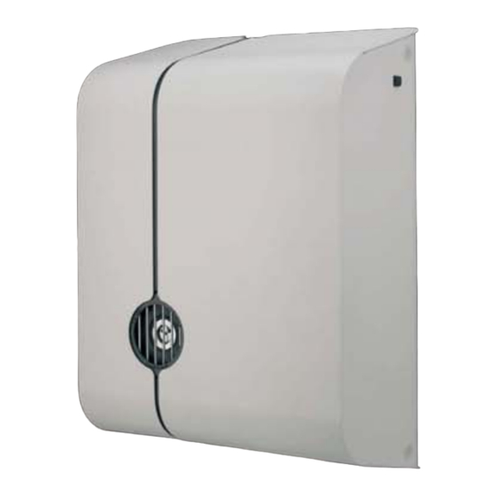
The addition of the V5, V10 and V20 to nozzle system means the machine is far the SmokeCloak range offers a new level more versatile in terms of where it can be of raw power in terms of the amount of positioned within a room and also the output these units are able to produce. -
Page 7: In The Box
In The Box Before attempting to install the machine it is advisable to ensure that you have all the required components. Upon opening your VALI box you should find: x1 off VALI unit (V5/V10/V20) Check serial labels to ensure the correct voltage x1 off Grille Plate Assembly x1 off Installation Bracket x1 off Manual pack... -
Page 8: Quick Start Guide
Quick Start Guide To quickly prepare and fire your unit, the following steps should be taken. For more detail on anything below, see the full guide provided. Remove the machine, installation bracket and any other accessories 6. Use the 4 screws provided to secure provided from the box. -
Page 9: Specifications
Specification Dimensions (mm) 438 x 340 x 176 438 x 340 x 176 488 x 340 x 176 Weight (install) 11.65 kg 11.65 kg 14.1 kg Weight (shipped) 21.2 kg + box 21.2 kg + box 24.3 kg Weight (hanging) 20.15 kg 20.15 kg 23.15 kg... -
Page 10: Machine Layout
Machine Layout tamper switch 2. cooling fan 3. heat exchanger 4. output nozzle electronics module (containing main power board) batteries interface PCB fluid container grille plate pump (s) changeover valve - 10 -... -
Page 11: Prior To Installation
The SmokeCloak should be configured so that it can only activate when the burglar alarm is set. The SmokeCloak must not be configured to form a “man-trap” i.e. activate to cut off a means of escape. The SmokeCloak should not be installed to cover escape routes and staircases of areas that are still occupied. -
Page 12: Installation
This apparatus must be earthed. Connections are made to a plug-in terminal block. The SmokeCloak should be connected to a standard 13 amp fused spur. Flexible mains cables must have a minimum cross-section area of 1.25 mm 2 (and must be BASEC approved in the UK). -
Page 13: Mounting The Machine
Mounting the machine Wall Installation Screw the installation bracket to the wall as shown. 2. Ensure that the cables are routed through the brackets and fed through the grommet bushes. The access hole in the installation bracket should allow the cables to be easily fed into position. -
Page 14: Horizontal Installation
Horizontal Installation Principally the same 4 steps are followed for a ceiling installation: Screw the installation bracket into position on the ceiling or with the roofing system, alternatively 6 mm threaded hanging bars can be used. These should be located on the slots at the ends of the hanging bracket and tightly fastened into position. -
Page 15: Nozzle System
Choosing and changing the nozzle The VALI V5, V10 and V20 will all come as standard with no nozzle installed. It is the job of the installer to assess, install and test which of the three nozzles supplied should be used in order to ensure that the machine is best suited to the particular installation. -
Page 16: Installing The Nozzle For The First Time
Installing the correct nozzle for the first time: By making a quick assessment of the area to be protected by the SmokeCloak, decide which of the three available standard nozzles should be used. You can see examples on the previous page. -
Page 17: Changing The Nozzle
In order to change the nozzle: Remove both side covers from the machine. Remove the 4 screws that secure the grille plate in position, and remove grille plate. Using a pair of internal circlip pliers, remove the circlip, taking care not to lose the circlip. -
Page 18: Fluid
Fluid FL600-V fluid is used to generate the vapour cloud. This glycol based fluid is made to a special formula, which is designed to produce 40% obscuration of light at 40 cm with minimum condensation. Installing the Fluid Bottle Your VALI product will be supplied with a full fluid container installed. It will arrive with a sealed travel cap installed. -
Page 19: Changing The Fluid
It is essential that only genuine SmokeCloak fluid is used. Damage to the equipment and a possible health hazard is likely if incorrect fluid is used. The warranty on all of the equipment will also be void Changing the Fluid As part of the maintenance of the VALI it is essential that the fluid is replaced annually to ensure that the quality of the effect produced is maintained at the desired level. -
Page 20: Priming The Machine
Priming the machine Following either the initial installation of the fluid bottle or following changing of the bottle it is essential that a short test firing is carried out to ensure that the fluid feed pipes are correctly primed. Failure to follow this procedure will lead to delayed response time the first time the machine is fired following the service or, more significantly, a failure to observe a connection fault incurred during the installation or re-installation of the fluid bottle. -
Page 21: Batteries
Batteries The battery backup system provides power for the control electronics and pumps when mains electricity is removed. It is necessary that batteries are installed for correct operation. The batteries are installed on a dedicated bracket which is found behind the interface board: To install the batteries: Battery bracket Remove the two M4 screws that... - Page 22 The battery backup system requires 24 V d.c. - it is necessary to fit two 12 V 1.2 Ah batteries in series in the SmokeCloak. Do not use larger than 1.2 Ah capacity batteries to prevent fuse failure due to excessive charging current.
-
Page 23: Wiring Up The Machine
Wiring up the Machine The mains power and low voltage control signals are clamped to the installation bracket using the cable clamps provided. The cables should be routed through the cable guide provided on the back face of the bracket, then fed through the cable clamps (see page 13) and terminated with the supplied plugs. -
Page 24: Wiring The Batteries
Wiring the batteries Once the batteries are installed within the bracket provided they must then be wired together in series and also into the power board. Follow the instructions below – The battery loom provided should be used. It will contain a single blue wire used for linking the batteries in series and in addition a red and a black wire for connecting the wires back to the power board. -
Page 25: Power Board
Power Board Layout SPI Connection Fluid sensor terminal Mains Power inlet Battery terminal + Earthing Point Battery terminal - Fuse F1 (mains supply) Fuse F2 (battery circuit) Fuse F3 (24 V power supply) - 25 -... -
Page 26: Fuse Values
Fuse Values VALI V5/V10 VALI V20 Fuse F1 Fuse F1 110 V 15 A (HBC) 110 V 20 A (HBC) 208 V 10 A (HBC) 208 V 15 A (HBC) 230 V 10 A (HBC) 230 V 15 A (HBC) -
Page 27: Connection Details
Connection Details Mains Inlet + Pump 1 - Pump 1 + Pump 2 - Pump 2 Fluid Sensor Input TCO circuit TCO circuit Internal Fan PL10 Heater N1 PL11 + Thermocouple PL12 - Thermocouple PL13 Heater L PL14 Heater N1 PL15 C/O Valve PL16... -
Page 28: Interface Board
Interface board Layout 1. SPI connection 8. Sounder 2. Programming socket 9. Switch 1 3. LED output 10. Switch 2 4. PL1 11. Field bus connector 5. PL2 12. USB Interface 6. PL3 13. Test button connector 7. PL4 - 28 -... -
Page 29: Connection Details
Connection Details Status LEDS LEDS LD 1 Battery (on – ok) LD 2 Mains (on – ok) LD 3 System ready (on – ready) LD 4 Heater (on – heating) LD 5 Temperature fault (on – fault) LD 6 Low fluid (on ok, off fault) LD 7 No fluid (on ok, off fault) LD 8... -
Page 30: Interface Board Connections
Mains failure (default) / Backstop timer Under no circumstances should the on board power supplies of the SmokeCloak (terminals 1, 6, 19, and 20) be linked to any other 3rd party equipment e.g. alarm panels, additional power supplies, etc. as this could cause unexpected faults within the machines. - Page 31 In all other instances the panic input feature will override all other inhibit functions Connections between the SmokeCloak and the alarm panel are made to the interface board via four 6-way plug-in connectors. 10 LEDs also found on the interface board indicate information concerning the status of the SmokeCloak.
- Page 32 To use voltage removed signaling it is necessary to use the PC interface in order to make this selection on the set and trigger inputs only. Use the appropriate diagram below to interface the SmokeCloak to your alarm panel: - 32 -...
- Page 33 DISCLAIMER: Actual alarm panels may vary from those illustrated and MSS PROFESSIONAL can not be held responsible for faults due to incorrect installations. - 33 -...
-
Page 34: Fault Outputs
Fault Outputs Fault circuit connections at panel. SmokeCloak has two outputs that feed fault information back to the alarm panel. Low fluid output Terminals 15 and 16 are normally closed (default). These open if the bottle is less than one third full. - Page 35 Always ensure that this will not cause a problem within the installation. It is not desirable to have a full alarm condition and then a SmokeCloak activation just because of a fault condition. If the alarm panel is not capable of supporting local alarm only, for monitoring these circuits, then consider using a spare communicator line to central station.
-
Page 36: Demo/Test Button Wiring
Demo/Test button wiring. Although the VALI machines come with a dedicated test button found on the side cover of the machine, it is possible to create an additional test button for use whilst the covers are disengaged. This should be done by creating a link across the two contacts on the test button connector. See page 28 for details of connector. -
Page 37: Verification Sensor
2 and 5. The power for active devices (250 mA max) is taken from terminal 1 (+12 V) and terminal 6 (0 V). This input does not trigger the SmokeCloak, but holds off its activation despite an alarm trigger until the verification loop detects an intruder. -
Page 38: Cloaksensor
Cloaksensor The Cloaksensor detects and controls the amount of vapour produced by the SmokeCloak after the initial activation. The Cloaksensor requires careful siting. Fit the sensor in a position in the room which will provide an indication of the drop in vapour concentration, (normally in the centre of the area the machine is protecting. -
Page 39: Locations To Avoid
Locations to avoid for Cloaksensor • Near a decorative object, door, light fitting, window moulding etc., that may prevent smoke from entering the Cloaksensor. • Surfaces that are normally warmer or colder than the rest of the room (for example attic hatches, un-insulated exterior walls etc). -
Page 40: Wiring
Cloaksensor Wiring A 6-core lead is taken to the Cloaksensor for smoke density control from PL1 terminals 1, 3, 5 and 6. It is recommended that an extra pair is used as a tamper loop and simply returned in the Cloaksensor. - 40 -... -
Page 41: Setting The Timer
Setting the Timer In order to ensure the correct level of coverage it is necessary to set-up the initial fill time of the machine. This can be done in two ways: • Firstly the timers can be set manually using the interface board. •... - Page 42 Setting the Timers through the Interface Board In order to manually set the timers on the VALI range, 2 switches on the interface board can be used in conjunction with the status LEDS. The timer is set in terms of the number of single second units (using switch 1) and the number of 10 second units (using switch 2).
- Page 43 To modify the number of ten second units the timer is set to: Press switch 2 once, this will display the current setting. Now press switch 2 again to increment through until the desired number of 10 second units is reached. Once the LEDs reach 5, pressing the switch again will turn off all LEDs.
-
Page 44: Preparation For Final Test
Ensure that any fire detection system is put on test or the customer has control of it. SmokeCloak will activate all types of smoke detector. However, it will not activate heat or carbon monoxide detectors. -
Page 45: Maintenance
Maintenance The VALI machines require an annual maintenance check in order to sustain the correct levels of performance and security. This requires the following: • A full test of the system. This can be done using the manual test button on the side of the machine, with the machine in SAI (Service Active Input) mode. -
Page 46: Usb Interface
USB Interface Updating the registry Before installing or attempting to use any of the PC based tools, it is important that the following steps are taken in order to update the windows registry. Failure to do this can lead to problems connecting to the VALI. The registry updater can be found on the CD received with your product, in the \Drivers directory. -
Page 47: Installing The Drivers
Installing the VALI driver In order to create a connection between the VALI and your computer it is necessary to install the VALI as a driver so it will be recognised each time a link is made. In order to do this: Power up the VALI and use a USB cable to link the VALI to your PC or laptop. -
Page 48: Configuration Software
Installing the configuration software Copy the VALI configuration program that can be found on the CD to a local drive on the computer. NOTE: Default values are shown below. - 48 -... -
Page 49: Connecting To The Vali
Connecting to the VALI • Using the appropriate USB cable, create a link between the USB port on the interface board of the VALI and the computer. Allow sufficient time for the computer to recognize the VALI being connected, ignore any momentary error message displayed in this period. -
Page 50: Using The Software
Using the software 4. Timers Here the current values are displayed for Retrigger, Backstop and Run timers. They can also be manually adjusted by simply typing the desired value. Retrigger Sets the period of time between the end of the machine’s trigger cycle, before it re-fires in order to maintain the effect within a room. - Page 51 6. Input Polarity Highlighting the tick box will invert the polarity of the set and trigger input signals. In order ‘Write’ for this change to become active it is necessary to upload the changes by clicking the button (see above). 7.
- Page 52 11. Fault Suppress Ticking this box will suppress the critical fault when the system is set. 12. Main Fault (terminals 17 and 18) This allows the behaviour of the main fault to be selected. The drop down box allows alternation between inclusion or exclusion of mains failure. 13.
- Page 53 Exit This closes the configuration program. Help Launches a PDF copy of this manual which provides assistance with all aspects of the VALI machine. - 53 -...
-
Page 54: Installing And Using The Bootloader
Installing and using the bootloader The VALI machine contains bootloader software, this enables software updates to be installed via the USB link. For the latest software release please contact MSS Professional A/S. Insert the CD, open the bootloader directory and select the setup file. This will run the install program. - Page 55 Select the COMM port, as installed previously. Next click browse and locate the software file you wish to install. Now click upload. The program will ask if you wish to replace the existing software, select YES and the software will now install. Reboot the VALI and the unit will exit bootloader mode and restart complete with the new software.
-
Page 56: Accessories
Accessories Fluid FL600-V SmokeCloak FL600-V is an exclusive mixture of deionised water and food grade glycols. The formula that has been developed through many years of experience and R&D gives a unique combination of density and hang time. The SmokeCloak FL600-V fluid is very economical in the production of SmokeCloak vapour. -
Page 57: Cloaksensor
Cloaksensor CS07A The SmokeCloak CS07 Cloaksensor is the part of the system that detects whether the room has the correct amount of vapour and sends a signal to the SmokeCloak machine requesting more vapour if the room is below the optimum level. -
Page 58: Strobe Ipl3000
SmokeCloak smoke density, to produce a blinding effect. The IPL 3000 is a high quality, very high intensity, security strobe light. The system is compatible with all of the SmokeCloak products, and is configured so that the operation of the IPL 3000 is controlled by the SmokeCloak. -
Page 59: Sounder Ipa125
The IPA 125 can be easily linked with other IPA 125 units in order to protect larger areas; the SmokeCloak products can be used to control the IPA 125. Dimensions: 686 x 103 x 41 mm Weight: 1.7 kg... -
Page 60: Voice Module
Voice Module The SmokeCloak CS140 voice module is a 12 V digital voice system, containing an embedded chip with a pre-recorded message. It is designed to be remotely positioned near to the normal access to the building and, if required, the protected area. -
Page 61: Batteries
Batteries The SmokeCloak is installed with two lead-acid batteries ensuring full smoke protection in the event of main power failure. The battery is from one of the world's leading manufactures of maintenance-free lead acid batteries. This ensures long service intervals, and low periodical costs. -
Page 62: Notes
Notes: - 62 -... - Page 63 - 63 -...
- Page 64 - 64 -...
Need help?
Do you have a question about the VALI V5 and is the answer not in the manual?
Questions and answers